EP0165490B1 - Auf einer gedruckten Schaltungskarte befestigter Aufnahmestecker für einen am Ende eines Kabels befestigten modularen Steckverbinder - Google Patents
Auf einer gedruckten Schaltungskarte befestigter Aufnahmestecker für einen am Ende eines Kabels befestigten modularen Steckverbinder Download PDFInfo
- Publication number
- EP0165490B1 EP0165490B1 EP85106179A EP85106179A EP0165490B1 EP 0165490 B1 EP0165490 B1 EP 0165490B1 EP 85106179 A EP85106179 A EP 85106179A EP 85106179 A EP85106179 A EP 85106179A EP 0165490 B1 EP0165490 B1 EP 0165490B1
- Authority
- EP
- European Patent Office
- Prior art keywords
- jack
- contact
- modular plug
- plug connector
- face
- Prior art date
- Legal status (The legal status is an assumption and is not a legal conclusion. Google has not performed a legal analysis and makes no representation as to the accuracy of the status listed.)
- Expired - Lifetime
Links
- 239000004020 conductor Substances 0.000 claims abstract description 30
- 230000005855 radiation Effects 0.000 claims abstract description 17
- 239000000463 material Substances 0.000 claims abstract description 12
- 238000003780 insertion Methods 0.000 claims description 11
- 230000037431 insertion Effects 0.000 claims description 11
- 238000010292 electrical insulation Methods 0.000 claims 1
- 239000004033 plastic Substances 0.000 description 8
- 229920003023 plastic Polymers 0.000 description 8
- 229910052782 aluminium Inorganic materials 0.000 description 3
- XAGFODPZIPBFFR-UHFFFAOYSA-N aluminium Chemical compound [Al] XAGFODPZIPBFFR-UHFFFAOYSA-N 0.000 description 3
- 238000004519 manufacturing process Methods 0.000 description 3
- 229910052751 metal Inorganic materials 0.000 description 3
- 239000002184 metal Substances 0.000 description 3
- HCHKCACWOHOZIP-UHFFFAOYSA-N Zinc Chemical compound [Zn] HCHKCACWOHOZIP-UHFFFAOYSA-N 0.000 description 2
- 238000004512 die casting Methods 0.000 description 2
- 239000011888 foil Substances 0.000 description 2
- PCHJSUWPFVWCPO-UHFFFAOYSA-N gold Chemical compound [Au] PCHJSUWPFVWCPO-UHFFFAOYSA-N 0.000 description 2
- 239000010931 gold Substances 0.000 description 2
- 229910052737 gold Inorganic materials 0.000 description 2
- 238000009413 insulation Methods 0.000 description 2
- 229910052725 zinc Inorganic materials 0.000 description 2
- 239000011701 zinc Substances 0.000 description 2
- 229920002799 BoPET Polymers 0.000 description 1
- 229910000906 Bronze Inorganic materials 0.000 description 1
- 239000005041 Mylar™ Substances 0.000 description 1
- OAICVXFJPJFONN-UHFFFAOYSA-N Phosphorus Chemical compound [P] OAICVXFJPJFONN-UHFFFAOYSA-N 0.000 description 1
- 229910045601 alloy Inorganic materials 0.000 description 1
- 239000000956 alloy Substances 0.000 description 1
- 238000005452 bending Methods 0.000 description 1
- 239000010974 bronze Substances 0.000 description 1
- 239000011248 coating agent Substances 0.000 description 1
- 238000000576 coating method Methods 0.000 description 1
- 238000010276 construction Methods 0.000 description 1
- 238000007796 conventional method Methods 0.000 description 1
- KUNSUQLRTQLHQQ-UHFFFAOYSA-N copper tin Chemical compound [Cu].[Sn] KUNSUQLRTQLHQQ-UHFFFAOYSA-N 0.000 description 1
- 238000000034 method Methods 0.000 description 1
- 239000011347 resin Substances 0.000 description 1
- 229920005989 resin Polymers 0.000 description 1
- 239000000126 substance Substances 0.000 description 1
Images




Classifications
-
- H—ELECTRICITY
- H01—ELECTRIC ELEMENTS
- H01R—ELECTRICALLY-CONDUCTIVE CONNECTIONS; STRUCTURAL ASSOCIATIONS OF A PLURALITY OF MUTUALLY-INSULATED ELECTRICAL CONNECTING ELEMENTS; COUPLING DEVICES; CURRENT COLLECTORS
- H01R12/00—Structural associations of a plurality of mutually-insulated electrical connecting elements, specially adapted for printed circuits, e.g. printed circuit boards [PCB], flat or ribbon cables, or like generally planar structures, e.g. terminal strips, terminal blocks; Coupling devices specially adapted for printed circuits, flat or ribbon cables, or like generally planar structures; Terminals specially adapted for contact with, or insertion into, printed circuits, flat or ribbon cables, or like generally planar structures
- H01R12/70—Coupling devices
- H01R12/71—Coupling devices for rigid printing circuits or like structures
- H01R12/712—Coupling devices for rigid printing circuits or like structures co-operating with the surface of the printed circuit or with a coupling device exclusively provided on the surface of the printed circuit
- H01R12/716—Coupling device provided on the PCB
-
- H—ELECTRICITY
- H01—ELECTRIC ELEMENTS
- H01R—ELECTRICALLY-CONDUCTIVE CONNECTIONS; STRUCTURAL ASSOCIATIONS OF A PLURALITY OF MUTUALLY-INSULATED ELECTRICAL CONNECTING ELEMENTS; COUPLING DEVICES; CURRENT COLLECTORS
- H01R13/00—Details of coupling devices of the kinds covered by groups H01R12/70 or H01R24/00 - H01R33/00
- H01R13/648—Protective earth or shield arrangements on coupling devices, e.g. anti-static shielding
- H01R13/658—High frequency shielding arrangements, e.g. against EMI [Electro-Magnetic Interference] or EMP [Electro-Magnetic Pulse]
- H01R13/6581—Shield structure
-
- H—ELECTRICITY
- H01—ELECTRIC ELEMENTS
- H01R—ELECTRICALLY-CONDUCTIVE CONNECTIONS; STRUCTURAL ASSOCIATIONS OF A PLURALITY OF MUTUALLY-INSULATED ELECTRICAL CONNECTING ELEMENTS; COUPLING DEVICES; CURRENT COLLECTORS
- H01R13/00—Details of coupling devices of the kinds covered by groups H01R12/70 or H01R24/00 - H01R33/00
- H01R13/02—Contact members
- H01R13/33—Contact members made of resilient wire
-
- H—ELECTRICITY
- H01—ELECTRIC ELEMENTS
- H01R—ELECTRICALLY-CONDUCTIVE CONNECTIONS; STRUCTURAL ASSOCIATIONS OF A PLURALITY OF MUTUALLY-INSULATED ELECTRICAL CONNECTING ELEMENTS; COUPLING DEVICES; CURRENT COLLECTORS
- H01R13/00—Details of coupling devices of the kinds covered by groups H01R12/70 or H01R24/00 - H01R33/00
- H01R13/46—Bases; Cases
- H01R13/502—Bases; Cases composed of different pieces
- H01R13/506—Bases; Cases composed of different pieces assembled by snap action of the parts
-
- H—ELECTRICITY
- H01—ELECTRIC ELEMENTS
- H01R—ELECTRICALLY-CONDUCTIVE CONNECTIONS; STRUCTURAL ASSOCIATIONS OF A PLURALITY OF MUTUALLY-INSULATED ELECTRICAL CONNECTING ELEMENTS; COUPLING DEVICES; CURRENT COLLECTORS
- H01R13/00—Details of coupling devices of the kinds covered by groups H01R12/70 or H01R24/00 - H01R33/00
- H01R13/648—Protective earth or shield arrangements on coupling devices, e.g. anti-static shielding
- H01R13/652—Protective earth or shield arrangements on coupling devices, e.g. anti-static shielding with earth pin, blade or socket
-
- H—ELECTRICITY
- H01—ELECTRIC ELEMENTS
- H01R—ELECTRICALLY-CONDUCTIVE CONNECTIONS; STRUCTURAL ASSOCIATIONS OF A PLURALITY OF MUTUALLY-INSULATED ELECTRICAL CONNECTING ELEMENTS; COUPLING DEVICES; CURRENT COLLECTORS
- H01R24/00—Two-part coupling devices, or either of their cooperating parts, characterised by their overall structure
- H01R24/60—Contacts spaced along planar side wall transverse to longitudinal axis of engagement
- H01R24/62—Sliding engagements with one side only, e.g. modular jack coupling devices
-
- H—ELECTRICITY
- H01—ELECTRIC ELEMENTS
- H01R—ELECTRICALLY-CONDUCTIVE CONNECTIONS; STRUCTURAL ASSOCIATIONS OF A PLURALITY OF MUTUALLY-INSULATED ELECTRICAL CONNECTING ELEMENTS; COUPLING DEVICES; CURRENT COLLECTORS
- H01R4/00—Electrically-conductive connections between two or more conductive members in direct contact, i.e. touching one another; Means for effecting or maintaining such contact; Electrically-conductive connections having two or more spaced connecting locations for conductors and using contact members penetrating insulation
- H01R4/02—Soldered or welded connections
Definitions
- jacks for modular plug connectors have been designed for connection to a printed circuit board.
- Rear part 16 is preferably molded of any suitable dielectric plastic material, such as ABS, and includes a block portion 70 having a front face 72, rear face 74 and side faces 76.
- An opening 78 is formed through block portion 70 opening at the front and rear faces 72 and 74 adapted to receive the frame portion 38 of front part 14 as described below.
- a deep cavity 80 is formed in block portion 70 opening onto the front face 72 thereof defining inwardly facing side faces 81 which are coplanar with respective side faces 50 of front part 14 when the jack is assembled as described below.
- the cavity terminates at a rear wall 82 in which a plurality of equally spaced slots 84 are formed.
- the rear wall terminates somewhat above the lower edges of side faces 76 and has lateral edges 82a which are spaced from respective side walls of block portion 16 as seen in Fig. 2.
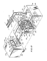
- Jack 210 comprises a housing 212 constructed of three parts, namely front part 214, rear part 216 and intermediate part 218, and a plurality of contacts 220.
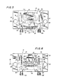
- the jack parts 214, 216 and 218 are lockingly interfitted as described below to define a cavity or receptacle 222 (Figs. 12 and 13) for receiving a modular plug connector having flat contact terminals 224 (Fig. 13) and to reliably hold the jack contacts 220 so that they are entirely enclosed within the housing 212 except for downwardly projecting portions 220a (Figs. 1, 12 and 13) which are inserted into the printed circuit board.
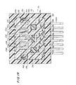
- a corresponding plurality of lower rear grooves 280a-280h are formed in rear face 266 below recess 276 which extend from recess 276 into the bottom face 272 of block portion 262. As is apparent from Figs. 10 and 14, the inter-groove spacing between lower grooves 280 is greater than that between upper grooves 278.
- a modular plug connector having flat contact terminals 224 is inserted into jack receptacle 222 and as seen in Fig. 13, each terminal 224 engages a contact portion 220h of a respective contact to flex it to the position shown by solid lines in Fig. 13.
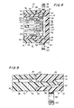
- the free ends of contact portions 220h are precisely positioned by being captured within the slots defined between walls 320. Moreover, it is not possible to permanently deform the contacts since undue deformation is prevented by the presence of backing surface 318.
Landscapes
- Coupling Device And Connection With Printed Circuit (AREA)
- Details Of Connecting Devices For Male And Female Coupling (AREA)
- Connector Housings Or Holding Contact Members (AREA)
- Multi-Conductor Connections (AREA)
Claims (17)
Priority Applications (1)
| Application Number | Priority Date | Filing Date | Title |
|---|---|---|---|
| AT85106179T ATE56316T1 (de) | 1984-05-21 | 1985-05-20 | Auf einer gedruckten schaltungskarte befestigter aufnahmestecker fuer einen am ende eines kabels befestigten modularen steckverbinder. |
Applications Claiming Priority (2)
| Application Number | Priority Date | Filing Date | Title |
|---|---|---|---|
| US06/612,722 US4641901A (en) | 1984-01-16 | 1984-05-21 | Printed circuit board jack for modular plug connector terminated cord |
| US612722 | 1990-11-13 |
Publications (3)
| Publication Number | Publication Date |
|---|---|
| EP0165490A2 EP0165490A2 (de) | 1985-12-27 |
| EP0165490A3 EP0165490A3 (en) | 1988-09-14 |
| EP0165490B1 true EP0165490B1 (de) | 1990-09-05 |
Family
ID=24454387
Family Applications (1)
| Application Number | Title | Priority Date | Filing Date |
|---|---|---|---|
| EP85106179A Expired - Lifetime EP0165490B1 (de) | 1984-05-21 | 1985-05-20 | Auf einer gedruckten Schaltungskarte befestigter Aufnahmestecker für einen am Ende eines Kabels befestigten modularen Steckverbinder |
Country Status (6)
| Country | Link |
|---|---|
| US (1) | US4641901A (de) |
| EP (1) | EP0165490B1 (de) |
| JP (1) | JPH081818B2 (de) |
| AT (1) | ATE56316T1 (de) |
| CA (1) | CA1243090A (de) |
| DE (1) | DE3579506D1 (de) |
Families Citing this family (30)
| Publication number | Priority date | Publication date | Assignee | Title |
|---|---|---|---|---|
| US4618207A (en) * | 1985-06-05 | 1986-10-21 | Molex Incorporated | Two piece modular receptacle |
| US4732568A (en) * | 1986-03-17 | 1988-03-22 | Virginia Plastics Company | Electrical connector with integral ground strap for shielded cable |
| GB8618415D0 (en) * | 1986-07-29 | 1986-09-03 | Bicc Plc | Connection unit |
| JP2688195B2 (ja) * | 1987-04-15 | 1997-12-08 | 松下電工株式会社 | テレホンモジユラージヤツク |
| US4941833A (en) * | 1988-10-06 | 1990-07-17 | Burndy Corporation | Controlled impedance plug and receptacle |
| US4950172A (en) * | 1989-10-10 | 1990-08-21 | Itt Corporation | Connector with interceptor plate |
| US5156554A (en) * | 1989-10-10 | 1992-10-20 | Itt Corporation | Connector interceptor plate arrangement |
| US5035632A (en) * | 1989-10-10 | 1991-07-30 | Itt Corporation | Card connector with interceptor plate |
| GB2243033A (en) * | 1990-02-16 | 1991-10-16 | Brand Rex Ltd | Electric connector |
| JPH088552Y2 (ja) * | 1990-05-29 | 1996-03-06 | モレックス インコーポレーテッド | 狭ピッチ用ボードとボードの接続用電気コネクタ |
| USD378207S (en) * | 1990-05-30 | 1997-02-25 | Jin-Rei Tsai | Data connector |
| US5064387A (en) * | 1990-06-12 | 1991-11-12 | Thomas & Betts Corporation | Shielded electrical jack connector |
| US5118310A (en) * | 1991-03-06 | 1992-06-02 | Panduit Corp. | Central latch modular telephone connector |
| US5273460A (en) * | 1991-09-17 | 1993-12-28 | Hosiden Corporation | Electrical parts for surface mounting |
| US5176349A (en) * | 1992-03-27 | 1993-01-05 | Amp Incorporated | Post retention arrangement |
| US5489219A (en) * | 1994-05-24 | 1996-02-06 | The Whitaker Corporation | Self-retaining board lock |
| DE4425748C1 (de) * | 1994-07-21 | 1995-07-27 | Krone Ag | Elektrischer Steckverbinder |
| TW421300U (en) * | 1998-03-25 | 2001-02-01 | Insert Entpr Co Ltd | Lead frame of connector |
| IL139807A0 (en) * | 1998-06-02 | 2002-02-10 | Stewart Connector Systems Inc | High frequency electrical connector assembly such as multi-port multi-level connector assembly |
| TW444959U (en) * | 1999-02-19 | 2001-07-01 | Berg Electronics Mfg | Modular jack with lead frame insert |
| KR100331163B1 (ko) * | 1999-05-11 | 2002-04-01 | 구자홍 | 전자파 억제장치 |
| US6554653B2 (en) | 2001-03-16 | 2003-04-29 | Adc Telecommunications, Inc. | Telecommunications connector with spring assembly and method for assembling |
| US6848943B2 (en) * | 2002-04-16 | 2005-02-01 | Pulse Engineering, Inc. | Shielded connector assembly and method of manufacturing |
| EP1734616A3 (de) * | 2005-06-17 | 2007-01-10 | YCL Mechanical Co., Ltd. | Kontakt für Signalübertragungsverbinder |
| US7665890B2 (en) | 2006-06-22 | 2010-02-23 | Watlow Electric Manufacturing Company | Temperature sensor assembly and method of manufacturing thereof |
| US7722362B2 (en) * | 2006-06-22 | 2010-05-25 | Watlow Electric Manufacturing Company | Sensor adaptor circuit housing incapsulating connection of an input connector with a wire |
| JP5728248B2 (ja) * | 2011-02-22 | 2015-06-03 | 矢崎総業株式会社 | コネクタの取付構造 |
| WO2012116043A1 (en) | 2011-02-25 | 2012-08-30 | Magna Electronics Inc. | Vehicular camera with aligned housing members and electrical connection between aligned housing members |
| US9318432B2 (en) * | 2012-10-31 | 2016-04-19 | Qualcomm Technologies International, Ltd. | Shielded system |
| CA3024542C (en) * | 2017-11-21 | 2026-03-31 | Legrand DPC, LLC | Shielded high density jack |
Family Cites Families (17)
| Publication number | Priority date | Publication date | Assignee | Title |
|---|---|---|---|---|
| US3699498A (en) * | 1970-04-30 | 1972-10-17 | Bell Telephone Labor Inc | Devices for making electrical connections |
| US3860316A (en) * | 1973-07-06 | 1975-01-14 | Western Electric Co | Electrical connecting devices for terminating cords and methods of assembling the devices to cords |
| US4224485A (en) * | 1978-10-16 | 1980-09-23 | Bell Telephone Laboratories, Incorporated | Telephone jack |
| US4274691A (en) * | 1978-12-05 | 1981-06-23 | Amp Incorporated | Modular jack |
| US4211462A (en) * | 1979-01-22 | 1980-07-08 | Stewart Stamping Corporation, A Division Of Insilco Corp. | Electrical connector for termination cords with improved locking means |
| US4235501A (en) * | 1979-03-20 | 1980-11-25 | Bell Telephone Laboratories, Incorporated | Connector |
| US4202593A (en) * | 1979-04-20 | 1980-05-13 | Amp Incorporated | Jack |
| JPS5935962Y2 (ja) * | 1979-06-15 | 1984-10-04 | 星電器製造株式会社 | コネクタ |
| US4423288A (en) * | 1979-10-29 | 1983-12-27 | Northern Telecom Limited | Modular telephone jack |
| JPS5792764A (en) * | 1980-10-07 | 1982-06-09 | Amp Inc | Shielding electric connector |
| US4397513A (en) * | 1981-04-08 | 1983-08-09 | Amp Incorporated | Cartridge holder and connector system |
| JPS58380U (ja) * | 1981-06-25 | 1983-01-05 | 第一電子工業株式会社 | 電気コネクタ |
| US4457575A (en) * | 1982-09-21 | 1984-07-03 | Amp Incorporated | Electrical connector having improved shielding and keying systems |
| US4497526A (en) * | 1983-03-28 | 1985-02-05 | Amp Incorporated | Circuit board housing having self-contained modular jack |
| US4516825A (en) * | 1983-07-11 | 1985-05-14 | Stewart Stamping Corporation | Modular connector for terminating EMI/RFI shielded cordage |
| US4506944A (en) * | 1983-07-11 | 1985-03-26 | Stewart Stamping Corporation | Modular connector for terminating EMI/RFI shielded cordage and cord terminated thereby |
| US4537459A (en) * | 1984-01-16 | 1985-08-27 | Stewart Stamping Corporation | Jack for EMI/RFI shield terminating modular plug connector |
-
1984
- 1984-05-21 US US06/612,722 patent/US4641901A/en not_active Expired - Fee Related
-
1985
- 1985-05-14 CA CA000481481A patent/CA1243090A/en not_active Expired
- 1985-05-20 DE DE8585106179T patent/DE3579506D1/de not_active Expired - Fee Related
- 1985-05-20 EP EP85106179A patent/EP0165490B1/de not_active Expired - Lifetime
- 1985-05-20 AT AT85106179T patent/ATE56316T1/de not_active IP Right Cessation
- 1985-05-21 JP JP60107095A patent/JPH081818B2/ja not_active Expired - Lifetime
Also Published As
| Publication number | Publication date |
|---|---|
| DE3579506D1 (de) | 1990-10-11 |
| CA1243090A (en) | 1988-10-11 |
| EP0165490A3 (en) | 1988-09-14 |
| JPH081818B2 (ja) | 1996-01-10 |
| US4641901A (en) | 1987-02-10 |
| JPS60254573A (ja) | 1985-12-16 |
| EP0165490A2 (de) | 1985-12-27 |
| ATE56316T1 (de) | 1990-09-15 |
Similar Documents
| Publication | Publication Date | Title |
|---|---|---|
| US4641901A (en) | Printed circuit board jack for modular plug connector terminated cord | |
| US4767355A (en) | Jack and connector | |
| US4653837A (en) | Jack and connector | |
| EP0224200B1 (de) | Abgeschirmte Steckerbuchse-Steckverbindung | |
| US5059140A (en) | Shielded plug and jack connector | |
| US4838811A (en) | Modular connector with EMI countermeasure | |
| US4457575A (en) | Electrical connector having improved shielding and keying systems | |
| US4457570A (en) | Connector for mating modular plug with printed circuit board | |
| US4889503A (en) | Shielded plug and jack connector | |
| US6390852B1 (en) | Cable connector assembly with an improved grounding structure | |
| US4902242A (en) | Panel mount, cable terminable connector with die cast housing and drawn shell | |
| US5244415A (en) | Shielded electrical connector and cable | |
| US5785557A (en) | Electrical connector with protection for electrical contacts | |
| EP0590667B1 (de) | Kabelverbinder hocher Packungsdichte | |
| US4451099A (en) | Electrical connector having commoning member | |
| US4619487A (en) | Flat cable connector with grounding clip | |
| US5938476A (en) | Cable connector assembly | |
| US6168466B1 (en) | Shielded electrical connector | |
| JP2911860B2 (ja) | 低プロフィールコネクタシステム | |
| US4516825A (en) | Modular connector for terminating EMI/RFI shielded cordage | |
| EP0624928B1 (de) | Abgeschirmte elektrische Verbinderanordnung | |
| EP0671785A1 (de) | Abgeschirmte Steckbuchse mit niedrigem Profil | |
| US20040259421A1 (en) | Cable connector assembly having improved shield members | |
| JPH02195675A (ja) | 低プロファイルシールドジャッキ | |
| US4537459A (en) | Jack for EMI/RFI shield terminating modular plug connector |
Legal Events
| Date | Code | Title | Description |
|---|---|---|---|
| PUAI | Public reference made under article 153(3) epc to a published international application that has entered the european phase |
Free format text: ORIGINAL CODE: 0009012 |
|
| AK | Designated contracting states |
Designated state(s): AT BE CH DE FR GB IT LI LU NL SE |
|
| RAP1 | Party data changed (applicant data changed or rights of an application transferred) |
Owner name: STEWART STAMPING CORPORATION (A DELAWARE CORPORATI |
|
| PUAL | Search report despatched |
Free format text: ORIGINAL CODE: 0009013 |
|
| AK | Designated contracting states |
Kind code of ref document: A3 Designated state(s): AT BE CH DE FR GB IT LI LU NL SE |
|
| 17P | Request for examination filed |
Effective date: 19881031 |
|
| 17Q | First examination report despatched |
Effective date: 19890130 |
|
| GRAA | (expected) grant |
Free format text: ORIGINAL CODE: 0009210 |
|
| AK | Designated contracting states |
Kind code of ref document: B1 Designated state(s): AT BE CH DE FR GB IT LI LU NL SE |
|
| REF | Corresponds to: |
Ref document number: 56316 Country of ref document: AT Date of ref document: 19900915 Kind code of ref document: T |
|
| ET | Fr: translation filed | ||
| REF | Corresponds to: |
Ref document number: 3579506 Country of ref document: DE Date of ref document: 19901011 |
|
| ITF | It: translation for a ep patent filed | ||
| ITTA | It: last paid annual fee | ||
| PLBE | No opposition filed within time limit |
Free format text: ORIGINAL CODE: 0009261 |
|
| STAA | Information on the status of an ep patent application or granted ep patent |
Free format text: STATUS: NO OPPOSITION FILED WITHIN TIME LIMIT |
|
| 26N | No opposition filed | ||
| EPTA | Lu: last paid annual fee | ||
| EAL | Se: european patent in force in sweden |
Ref document number: 85106179.6 |
|
| PGFP | Annual fee paid to national office [announced via postgrant information from national office to epo] |
Ref country code: GB Payment date: 19980421 Year of fee payment: 14 Ref country code: FR Payment date: 19980421 Year of fee payment: 14 |
|
| PGFP | Annual fee paid to national office [announced via postgrant information from national office to epo] |
Ref country code: CH Payment date: 19980506 Year of fee payment: 14 |
|
| PGFP | Annual fee paid to national office [announced via postgrant information from national office to epo] |
Ref country code: LU Payment date: 19980508 Year of fee payment: 14 |
|
| PGFP | Annual fee paid to national office [announced via postgrant information from national office to epo] |
Ref country code: BE Payment date: 19980512 Year of fee payment: 14 |
|
| PGFP | Annual fee paid to national office [announced via postgrant information from national office to epo] |
Ref country code: AT Payment date: 19980526 Year of fee payment: 14 |
|
| PGFP | Annual fee paid to national office [announced via postgrant information from national office to epo] |
Ref country code: NL Payment date: 19980531 Year of fee payment: 14 |
|
| PGFP | Annual fee paid to national office [announced via postgrant information from national office to epo] |
Ref country code: SE Payment date: 19980602 Year of fee payment: 14 |
|
| PGFP | Annual fee paid to national office [announced via postgrant information from national office to epo] |
Ref country code: DE Payment date: 19980630 Year of fee payment: 14 |
|
| PG25 | Lapsed in a contracting state [announced via postgrant information from national office to epo] |
Ref country code: LU Free format text: LAPSE BECAUSE OF NON-PAYMENT OF DUE FEES Effective date: 19990520 Ref country code: GB Free format text: LAPSE BECAUSE OF NON-PAYMENT OF DUE FEES Effective date: 19990520 Ref country code: AT Free format text: LAPSE BECAUSE OF NON-PAYMENT OF DUE FEES Effective date: 19990520 |
|
| PG25 | Lapsed in a contracting state [announced via postgrant information from national office to epo] |
Ref country code: SE Free format text: LAPSE BECAUSE OF NON-PAYMENT OF DUE FEES Effective date: 19990521 |
|
| PG25 | Lapsed in a contracting state [announced via postgrant information from national office to epo] |
Ref country code: LI Free format text: LAPSE BECAUSE OF NON-PAYMENT OF DUE FEES Effective date: 19990531 Ref country code: CH Free format text: LAPSE BECAUSE OF NON-PAYMENT OF DUE FEES Effective date: 19990531 Ref country code: BE Free format text: LAPSE BECAUSE OF NON-PAYMENT OF DUE FEES Effective date: 19990531 |
|
| BERE | Be: lapsed |
Owner name: STEWART STAMPING CORP. (A DELAWARE CORP.) Effective date: 19990531 |
|
| PG25 | Lapsed in a contracting state [announced via postgrant information from national office to epo] |
Ref country code: NL Free format text: LAPSE BECAUSE OF NON-PAYMENT OF DUE FEES Effective date: 19991201 |
|
| REG | Reference to a national code |
Ref country code: CH Ref legal event code: PL |
|
| GBPC | Gb: european patent ceased through non-payment of renewal fee |
Effective date: 19990520 |
|
| EUG | Se: european patent has lapsed |
Ref document number: 85106179.6 |
|
| PG25 | Lapsed in a contracting state [announced via postgrant information from national office to epo] |
Ref country code: FR Free format text: LAPSE BECAUSE OF NON-PAYMENT OF DUE FEES Effective date: 20000131 |
|
| NLV4 | Nl: lapsed or anulled due to non-payment of the annual fee |
Effective date: 19991201 |
|
| PG25 | Lapsed in a contracting state [announced via postgrant information from national office to epo] |
Ref country code: DE Free format text: LAPSE BECAUSE OF NON-PAYMENT OF DUE FEES Effective date: 20000301 |
|
| REG | Reference to a national code |
Ref country code: FR Ref legal event code: ST |