EP0165597A2 - Dichtende Laibung für ein Doppelschiebefenster - Google Patents
Dichtende Laibung für ein Doppelschiebefenster Download PDFInfo
- Publication number
- EP0165597A2 EP0165597A2 EP85107555A EP85107555A EP0165597A2 EP 0165597 A2 EP0165597 A2 EP 0165597A2 EP 85107555 A EP85107555 A EP 85107555A EP 85107555 A EP85107555 A EP 85107555A EP 0165597 A2 EP0165597 A2 EP 0165597A2
- Authority
- EP
- European Patent Office
- Prior art keywords
- sash
- sealing
- jamb liner
- run
- extrusion
- Prior art date
- Legal status (The legal status is an assumption and is not a legal conclusion. Google has not performed a legal analysis and makes no representation as to the accuracy of the status listed.)
- Withdrawn
Links
- 238000007789 sealing Methods 0.000 title claims abstract description 37
- 238000001125 extrusion Methods 0.000 claims abstract description 30
- 239000011347 resin Substances 0.000 claims abstract description 27
- 229920005989 resin Polymers 0.000 claims abstract description 27
- 239000011324 bead Substances 0.000 claims abstract description 20
- 239000000463 material Substances 0.000 claims abstract description 9
- 238000003780 insertion Methods 0.000 claims description 3
- 230000037431 insertion Effects 0.000 claims description 3
- 238000000034 method Methods 0.000 claims 4
- 230000002860 competitive effect Effects 0.000 description 2
- 238000004519 manufacturing process Methods 0.000 description 2
- 239000004743 Polypropylene Substances 0.000 description 1
- 239000007795 chemical reaction product Substances 0.000 description 1
- 230000004927 fusion Effects 0.000 description 1
- 238000009434 installation Methods 0.000 description 1
- -1 polypropylene Polymers 0.000 description 1
- 229920001155 polypropylene Polymers 0.000 description 1
- 229920000915 polyvinyl chloride Polymers 0.000 description 1
- 239000004800 polyvinyl chloride Substances 0.000 description 1
- 239000012858 resilient material Substances 0.000 description 1
- 239000007787 solid Substances 0.000 description 1
Images
Classifications
-
- E—FIXED CONSTRUCTIONS
- E06—DOORS, WINDOWS, SHUTTERS, OR ROLLER BLINDS IN GENERAL; LADDERS
- E06B—FIXED OR MOVABLE CLOSURES FOR OPENINGS IN BUILDINGS, VEHICLES, FENCES OR LIKE ENCLOSURES IN GENERAL, e.g. DOORS, WINDOWS, BLINDS, GATES
- E06B7/00—Special arrangements or measures in connection with doors or windows
- E06B7/16—Sealing arrangements on wings or parts co-operating with the wings
- E06B7/22—Sealing arrangements on wings or parts co-operating with the wings by means of elastic edgings, e.g. elastic rubber tubes; by means of resilient edgings, e.g. felt or plush strips, resilient metal strips
- E06B7/23—Plastic, sponge rubber, or like strips or tubes
- E06B7/2305—Plastic, sponge rubber, or like strips or tubes with an integrally formed part for fixing the edging
- E06B7/2307—Plastic, sponge rubber, or like strips or tubes with an integrally formed part for fixing the edging with a single sealing-line or -plane between the wing and the part co-operating with the wing
- E06B7/231—Plastic, sponge rubber, or like strips or tubes with an integrally formed part for fixing the edging with a single sealing-line or -plane between the wing and the part co-operating with the wing with a solid sealing part
-
- E—FIXED CONSTRUCTIONS
- E06—DOORS, WINDOWS, SHUTTERS, OR ROLLER BLINDS IN GENERAL; LADDERS
- E06B—FIXED OR MOVABLE CLOSURES FOR OPENINGS IN BUILDINGS, VEHICLES, FENCES OR LIKE ENCLOSURES IN GENERAL, e.g. DOORS, WINDOWS, BLINDS, GATES
- E06B3/00—Window sashes, door leaves, or like elements for closing wall or like openings; Layout of fixed or moving closures, e.g. windows in wall or like openings; Features of rigidly-mounted outer frames relating to the mounting of wing frames
- E06B3/32—Arrangements of wings characterised by the manner of movement; Arrangements of movable wings in openings; Features of wings or frames relating solely to the manner of movement of the wing
- E06B3/34—Arrangements of wings characterised by the manner of movement; Arrangements of movable wings in openings; Features of wings or frames relating solely to the manner of movement of the wing with only one kind of movement
- E06B3/42—Sliding wings; Details of frames with respect to guiding
- E06B3/44—Vertically-sliding wings
Definitions
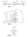
- Jamb liner 10 includes a pair of sash runs 11 and 12 separated by a parting bead 13.
- a pair of opposed projections 15 in each of the sash runs are L-shaped in cross section and disposed to confront each other.
- Spring covers can be mounted in the interlock formed by projections 15, and a friction shoe traveling with each sash can run in the track between projections 15.
- a resin web 16 preferably extends between sash runs 11 and 12 in the region of parting bead 13 to interconnect- the planes of the sash runs and brace their outer edges 21 and 22.
- Web 16 helps resist any squeezing force from trim stops 30 installed so tightly that they urge sash runs 11 and 12 together under parting bead 13.
- Web 16 also strengthens jamb liner 10 against twisting, making it easier to install.
- jamb liner 10 is formed as a generally known base extrusion ' 24 of substantially rigid resin material, preferably polyvinyl chloride.
- Resilient flange seals 25 arranged at outer sash run edges 21 and 22 are formed differently, however, as explained below.
- Flange seals 25, also extruded of resin material, are formed of a substantially resilient resin, such as polypropylene, having a substantially lower spring rate than the rigid resin of base extrusion 24. This allows flange elements 25 to be flexed or sprung from their home positions in response to light force and to resiliently spring back to their home positions after a flexing force is removed.
- a substantially resilient resin such as polypropylene
- Each flange element 25 includes a support limb 26 and a sealing fin 27, both of which are thinner in cross section than the rigid resin extrusion 24.
- support limb 26 and sealing fin 27 are preferably less than 0.5mm thick, compared with the more than 1.0mm thickness that is preferred for the base extrusion 24.
- sealing fins can be arranged relative to support limbs to form flange elements 25, but we prefer the configuration shown in FIGS. 1-3.
- Sealing fin 27 angles obliquely inward from a distal end 36 of support limb 26 toward the adjacent sash run 11 where it is disposed for resiliently engaging a sash 40.
- flange element 25 preferably leans toward the adjacent trim stop 30 as shown at the left edge of FIG. 1. Then when trim stop 30 is installed against the outer sash run edge 21 of jamb liner 10, it flexes flange element 25 inward; and flange element 25, in resistance to this, engages and seals against trim stop 30. This helps prevent air from leaking between the trim stops and the jamb liner and passing behind the sash runs.
- the oblique span of sealing fin 27 is wider than the space between trim stop 30 and sash 40 so that fin 27 is flexibly compressed between trim stop 30 and sash 40 as best shown in FIG. 2.
- This not only creates a seal between fin 27 engaging and pressing against the surface of sash 40, but it also presses the sash against parting bead 13. This tends to seal each sash both on the side engaged by _fin 27 and on the opposite side where the sash engages parting bead 13.
- the scope of the biased resilient spring range of sealing fin 27 is suggested by the distance between the solid and broken line positions of sealing flange 25 in FIG. 2. This is adequate to accommodate manufacturing tolerances in the thickness of a sash and to allow fin 27 to conform to slight irregularities in a sash.
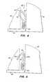
- sealing fin 27 It is also possible to reverse the orientation of sealing fin 27 to engage trim stop 30, rather than sash 40, as shown in FIG. 4.
- a flange element 25 oriented this way engages a surface of sash 40 in the region 36 -where the distal end of support limb 26 joins the proximal end of fin 27.
- a disadvantage with this arrangement is that the distal end of fin 27 extends outward from sash run edge 22 of base extrusion 24 where it may be damaged in shipment.
- FIG. 5 Another possibility, illustrated in FIG. 5, is an opposed pair of fins 27a and b each extending obliquely outward from the distal end 36 of support limb 26. Then one fin 27b can engage and seal against trim stop 30, leaving the opposite fin 27a disposed to engage and seal against a surface of sash 40.
- Such a double- finned configuration uses slightly more resilient material and leaves fin 27b extending beyond sash run edge 22 where it is exposed to shipment and installation damage.
- Sealing flanges 25 can be interconnected with base extrusion 24 in several ways. The differences in resin materials may inhibit a direct fusion bond, so we prefer a mechanical interlock such as shown in FIGS. 2 and 3. Other mechanical interlocks are also possible and can be combined with thermal forming accomplished as flange elements 25 are automatically joined to base extrusion 24.
- Our preferred mechanical interlock formed at the outer sash run edges 21 and 22, uses a groove between a pair of spaced-apart legs.23a and 23b having opposed projections 23c constricting the open end of the groove.
- Limbs 29, which tend to spring apart, are then trapped behind confronting lips 23c as shown in FIG. 2 to resist withdrawal of element 25 from base 24. Many variations on such an arrangement are possible.
- Base 24 and a pair of flange elements 25 can all be extruded simultaneously and united downstream of the extruders for forming jamb liner 10 continuously.
- Flange elements 25 can also be preextruded and fed from a supply to join extrusion 24 shortly after it is formed. It may even be possible to feed preextruded flange elements 25 through the extrusion head that forms extrusion 24, directly united with flange elements 25. Automatically joining flange elements 25 and extrusion 24 at extrusion speed eliminates post-assembly of separate components and forms jamb liner 10 as a single end product that can serve on both sides of double-hung window sash.
Landscapes
- Engineering & Computer Science (AREA)
- Civil Engineering (AREA)
- Structural Engineering (AREA)
- Specific Sealing Or Ventilating Devices For Doors And Windows (AREA)
- Support Devices For Sliding Doors (AREA)
Applications Claiming Priority (2)
| Application Number | Priority Date | Filing Date | Title |
|---|---|---|---|
| US06/622,103 US4606147A (en) | 1984-06-19 | 1984-06-19 | Sealing jamb liner for double-hung window sash |
| US622103 | 1996-03-26 |
Publications (2)
| Publication Number | Publication Date |
|---|---|
| EP0165597A2 true EP0165597A2 (de) | 1985-12-27 |
| EP0165597A3 EP0165597A3 (de) | 1986-12-30 |
Family
ID=24492952
Family Applications (1)
| Application Number | Title | Priority Date | Filing Date |
|---|---|---|---|
| EP85107555A Withdrawn EP0165597A3 (de) | 1984-06-19 | 1985-06-19 | Dichtende Laibung für ein Doppelschiebefenster |
Country Status (3)
| Country | Link |
|---|---|
| US (1) | US4606147A (de) |
| EP (1) | EP0165597A3 (de) |
| JP (1) | JPS61117378A (de) |
Families Citing this family (16)
| Publication number | Priority date | Publication date | Assignee | Title |
|---|---|---|---|---|
| USD300464S (en) | 1987-02-24 | 1989-03-28 | Davidson Jack E | Weatherstripping for doors and the like |
| US4916863A (en) * | 1989-06-02 | 1990-04-17 | Schlegel Corporation | Jamb liner weatherseal |
| US5375376A (en) * | 1993-01-21 | 1994-12-27 | Crane Plastics Company Limited Partnership | Polymeric sealing/spring strip and extrusion method of producing same |
| USD368534S (en) | 1994-11-17 | 1996-04-02 | Delaware Capital Formation Inc. | Interlocking thermal breaker extrusion |
| US20060169418A1 (en) * | 2002-07-22 | 2006-08-03 | Pella Corporation | Window covering leveling method |
| US20060130980A1 (en) * | 2002-07-22 | 2006-06-22 | Pella Corporation | Window covering leveling mechanism |
| US7066233B2 (en) * | 2002-07-22 | 2006-06-27 | Pella Corporation | Sliding operator for between the glass window coverings |
| US6736185B2 (en) * | 2002-07-22 | 2004-05-18 | Pella Corporation | Sliding operator for between the glass window coverings |
| US8302353B2 (en) | 2004-10-15 | 2012-11-06 | Thomas Bren | Water intrusion prevention method and apparatus |
| US7552562B2 (en) * | 2005-05-12 | 2009-06-30 | Marvin Lumber And Cedar Company | Structural filler system for a window or door |
| US7631465B2 (en) | 2005-05-12 | 2009-12-15 | Marvin Lumber And Cedar Company | Jamb adjustment and securement assembly and methods therefor |
| US8584426B2 (en) * | 2010-06-04 | 2013-11-19 | Milgard Manufacturing Incorporated | Sash binder |
| US10377569B1 (en) * | 2018-03-29 | 2019-08-13 | Nashville Wire Products Manufacturing Company, Llc | Perforated decking |
| USD946950S1 (en) * | 2018-04-10 | 2022-03-29 | SieMatic Möbelwerke GmbH & Co. KG | Section for furniture |
| USD920087S1 (en) | 2018-09-12 | 2021-05-25 | Megawall Pty Ltd | Connector for a building panel |
| USD942786S1 (en) * | 2018-10-18 | 2022-02-08 | SieMatic Möbelwerke GmbH & Co. KG | Furniture section |
Family Cites Families (11)
| Publication number | Priority date | Publication date | Assignee | Title |
|---|---|---|---|---|
| US2122366A (en) * | 1938-01-31 | 1938-06-28 | W J Dennis & Company | Weather strip construction |
| US2273279A (en) * | 1938-03-28 | 1942-02-17 | Louis A Macklanburg | Window sash assembly and weather strip therefor |
| US2744297A (en) * | 1953-07-13 | 1956-05-08 | Chamberlin Company Of America | Combination guide and weatherstrip for sliding window constructions |
| US2917788A (en) * | 1956-09-06 | 1959-12-22 | Abert A Kunkel | Liner for frame members |
| US3269074A (en) * | 1963-07-22 | 1966-08-30 | Armstadt Mfg Ltd | Sash and frame for windows and doors |
| US3499248A (en) * | 1968-02-26 | 1970-03-10 | Hans Baer | Prefabricated window and frame structure having removable sash-balanced window panels |
| US3633317A (en) * | 1970-07-01 | 1972-01-11 | Zegers Inc | Clip for combination weatherstrip and sash balance units |
| JPS4824360U (de) * | 1971-07-26 | 1973-03-22 | ||
| US4096665A (en) * | 1977-03-10 | 1978-06-27 | Ellingson Jr Chester W | Window sealing structure |
| JPS5613312Y2 (de) * | 1977-08-23 | 1981-03-27 | ||
| US4373295A (en) * | 1980-11-12 | 1983-02-15 | A.M.S. Corporation | Resilient friction sash balance |
-
1984
- 1984-06-19 US US06/622,103 patent/US4606147A/en not_active Expired - Fee Related
-
1985
- 1985-06-19 EP EP85107555A patent/EP0165597A3/de not_active Withdrawn
- 1985-11-19 JP JP60259640A patent/JPS61117378A/ja active Pending
Also Published As
| Publication number | Publication date |
|---|---|
| US4606147A (en) | 1986-08-19 |
| EP0165597A3 (de) | 1986-12-30 |
| JPS61117378A (ja) | 1986-06-04 |
Similar Documents
| Publication | Publication Date | Title |
|---|---|---|
| EP0165597A2 (de) | Dichtende Laibung für ein Doppelschiebefenster | |
| CA1167703A (en) | Window frame assembly with frame shaped locking member | |
| US4781003A (en) | Expansion joint seal, frame and assembly | |
| US4341255A (en) | Storm window | |
| US6182405B1 (en) | Window frame structure | |
| US4555885A (en) | Filler strip with locking clip | |
| CA2059620C (en) | Glazing bar system | |
| JP3678753B2 (ja) | スイッチキャビネットのフレーム構造のためのフレーム成形材 | |
| US4184297A (en) | Extruded plastic panel holding and jointing strips and window assemblies therewith | |
| US5155958A (en) | Fastening and support system for architectural panels | |
| US6478308B1 (en) | Replaceable door seal and retainer assemblies | |
| US3432966A (en) | Combination interlock and weather seal strip arrangement for relatively slidable closure members | |
| US4299008A (en) | Curtain rail | |
| US20080216424A1 (en) | Window joining system | |
| US5237787A (en) | Glazing element | |
| KR880004920A (ko) | 프로필 및 인접한 립-형 지퍼를 운반용 필름 웨브에 형성시키고 적용하는 장치 및 방법 | |
| US6484447B1 (en) | Seal for sectional door | |
| US4799332A (en) | Sliding window | |
| US3703061A (en) | Overhead door construction | |
| AU642141B2 (en) | Sectional doors and flexible hinge assemblies | |
| US5199219A (en) | Window jamb liner | |
| WO1990012187A1 (en) | Window to be inserted in an opening in a wall of sandwich-type | |
| WO1997018365A1 (en) | Panel sealing structure | |
| SK29594A3 (en) | Composite framing profile | |
| GB2065744A (en) | Building panels |
Legal Events
| Date | Code | Title | Description |
|---|---|---|---|
| PUAI | Public reference made under article 153(3) epc to a published international application that has entered the european phase |
Free format text: ORIGINAL CODE: 0009012 |
|
| AK | Designated contracting states |
Designated state(s): DE GB NL |
|
| PUAL | Search report despatched |
Free format text: ORIGINAL CODE: 0009013 |
|
| RAP1 | Party data changed (applicant data changed or rights of an application transferred) |
Owner name: CALDWELL MANUFACTURING COMPANY |
|
| AK | Designated contracting states |
Kind code of ref document: A3 Designated state(s): DE GB NL |
|
| STAA | Information on the status of an ep patent application or granted ep patent |
Free format text: STATUS: THE APPLICATION HAS BEEN WITHDRAWN |
|
| 18W | Application withdrawn |
Withdrawal date: 19870107 |
|
| RIN1 | Information on inventor provided before grant (corrected) |
Inventor name: DEWITT, VERN T. Inventor name: HALTOF, GARRY P. |