EP0165632A2 - Optical flat type cable, method of manufacturing same, and an optical cable composed of several flat type cables - Google Patents
Optical flat type cable, method of manufacturing same, and an optical cable composed of several flat type cables Download PDFInfo
- Publication number
- EP0165632A2 EP0165632A2 EP85200818A EP85200818A EP0165632A2 EP 0165632 A2 EP0165632 A2 EP 0165632A2 EP 85200818 A EP85200818 A EP 85200818A EP 85200818 A EP85200818 A EP 85200818A EP 0165632 A2 EP0165632 A2 EP 0165632A2
- Authority
- EP
- European Patent Office
- Prior art keywords
- optical
- fibres
- flat type
- lacquer
- cable
- Prior art date
- Legal status (The legal status is an assumption and is not a legal conclusion. Google has not performed a legal analysis and makes no representation as to the accuracy of the status listed.)
- Granted
Links
Images
Classifications
-
- G—PHYSICS
- G02—OPTICS
- G02B—OPTICAL ELEMENTS, SYSTEMS OR APPARATUS
- G02B6/00—Light guides; Structural details of arrangements comprising light guides and other optical elements, e.g. couplings
- G02B6/04—Light guides; Structural details of arrangements comprising light guides and other optical elements, e.g. couplings formed by bundles of fibres
- G02B6/06—Light guides; Structural details of arrangements comprising light guides and other optical elements, e.g. couplings formed by bundles of fibres the relative position of the fibres being the same at both ends, e.g. for transporting images
- G02B6/08—Light guides; Structural details of arrangements comprising light guides and other optical elements, e.g. couplings formed by bundles of fibres the relative position of the fibres being the same at both ends, e.g. for transporting images with fibre bundle in form of plate
-
- G—PHYSICS
- G02—OPTICS
- G02B—OPTICAL ELEMENTS, SYSTEMS OR APPARATUS
- G02B6/00—Light guides; Structural details of arrangements comprising light guides and other optical elements, e.g. couplings
- G02B6/24—Coupling light guides
- G02B6/255—Splicing of light guides, e.g. by fusion or bonding
- G02B6/2558—Reinforcement of splice joint
-
- B—PERFORMING OPERATIONS; TRANSPORTING
- B29—WORKING OF PLASTICS; WORKING OF SUBSTANCES IN A PLASTIC STATE IN GENERAL
- B29D—PRODUCING PARTICULAR ARTICLES FROM PLASTICS OR FROM SUBSTANCES IN A PLASTIC STATE
- B29D11/00—Producing optical elements, e.g. lenses or prisms
- B29D11/00663—Production of light guides
-
- G—PHYSICS
- G02—OPTICS
- G02B—OPTICAL ELEMENTS, SYSTEMS OR APPARATUS
- G02B6/00—Light guides; Structural details of arrangements comprising light guides and other optical elements, e.g. couplings
- G02B6/24—Coupling light guides
- G02B6/255—Splicing of light guides, e.g. by fusion or bonding
- G02B6/2555—Alignment or adjustment devices for aligning prior to splicing
-
- G—PHYSICS
- G02—OPTICS
- G02B—OPTICAL ELEMENTS, SYSTEMS OR APPARATUS
- G02B6/00—Light guides; Structural details of arrangements comprising light guides and other optical elements, e.g. couplings
- G02B6/44—Mechanical structures for providing tensile strength and external protection for fibres, e.g. optical transmission cables
- G02B6/4401—Optical cables
- G02B6/4403—Optical cables with ribbon structure
-
- G—PHYSICS
- G02—OPTICS
- G02B—OPTICAL ELEMENTS, SYSTEMS OR APPARATUS
- G02B6/00—Light guides; Structural details of arrangements comprising light guides and other optical elements, e.g. couplings
- G02B6/44—Mechanical structures for providing tensile strength and external protection for fibres, e.g. optical transmission cables
- G02B6/4479—Manufacturing methods of optical cables
- G02B6/448—Ribbon cables
Definitions
- the invention relates to an optical flat type cable in which several parallel extending optical fibres situated in a flat plane are bonded together.
- Such a cable is known from the German Offen- legungsschrift 27.24.536, page 3, first paragraph. It is stated that, although the cable has a good flexibility, it has on the other hand a low strength and breaks easily. It is suggested in the above-mentioned German Offen- legungsschrift to provide each fibre with a fixed or loose protecting cover and to provide thereon a cover of a soft synthetic resin. The fibres are interconnected via the cover of the soft synthetic resin. If desired, an adhesive may be used.
- extra covers such as that of the soft synthetic resin, causes the manufacture of the optical flat type cable to consume more time and effort and hence to become more expensive. Moreover, as a result of the extra covers, extra forces will also occur, for example, as a result of bending the cable or of temperature variations. As a result of this, an extra signal loss will occur.
- Another object of the invention is to provide an optical flat type cable which is very flexible and moreover has a good mechanical strength.
- an optical flat type cable in which the signal loss of the optical fibres as a result of the processing to form a flat type cable, is extremely low.
- a further object of the invention is to provide an optical cable in which a number of optical flat type cables have been combined.
- Still a further object is to provide an efficacious, method of manufacturing an optical flat type cable.
- optical flat type cable of the type mentioned in the opening paragraph which is characterized in that the optical fibres are interconnected by a light-cured lacquer of acrylic acid esters which is present only on the facing circumferential parts of the optical fibres.
- optical fibres in the cable according to the invention engage each other or engage each other substantially. This means thai/the spacing between the fibres is at most 10 / um.
- the lacquer of acrylic acid esters prior to curing, comprises a mixture of mono-, di-, tri- and/or tetraesters of acrylic acid to which other light-curable ingredients such as N-vinylpyrrolidone may have been added.
- the lacquer comprises an initiator, for example, a benzoin isobutyl ether which is commercially available under the trade name Irgacure.
- useful acrylic acid esters are alkanediol acrylates, such as1,6-hexanediol diacrylate, alkene glycol diacrylates, such as tripropylene glycol diacrylate, trimethylol propane triacrylate, polyester acrylates, epoxy acrylate and urethane acrylate.
- the invention also relates to an optical cable which comprises a pack of a number of stacked optical flat type cables as described hereinbefore, which pack is twisted about its longitudinal axis and is surrounded by a loose tubular cover.
- the cover is usually a tube of a synthetic resin.
- the cover may comprise reinforcing elements, such as longitudinally extending reinforcing wires or reinforcing fibres, for example, polyaramide fibres, or steel wires, Further protective covers or an armouring may be provided around the cover.
- Several optical cables may also be grouped together and be provided with one or more common covers or a common armouring.
- the optical cable according to the invention excels by its simple construction and cheap method of manufacture and hence is very suitable for practical use on a large scale.
- the invention furthermore relates to method of manufacturing an optical flat type cable.
- the manufacturing method according to the invention is characterized in that a number of parallel extending optical fibres are guided over a first roller or system of rollers which at its surface has a layer of a light-curable lacquer in which the fibres, on passing over the roller, are provided on one side with a layer of lacquer, the fibres are then guided over a second roller or system of rollers the shaft of which is at right angles to that of the first roller or system of rollers, the fibres being rotated through an angle of 90 0 and the resulting assembly of optical fibres being exposed to light.
- the special aspect of the method according to the invention is that due to the rotation of the fibres through 90 0 the fibre bundle is self-calibrating.
- the fibres do the centring themselves, i.e. they automatically engage each other, the provided lacquer being present only between the facing circumferential parts of the fibres.
- an important advantage of the method according to the invention is that no separate calibrating or centring device is necessary to get the fibres in their places, i.e. parallel against each other.
- Another inportant advantage is that the lacquer also lands in the correct place, i.e. only between the fibres.
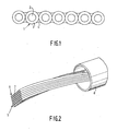
- Reference numeral 1 in Figure 1 denotes an optical fibre (glass fibre) as it is marketed by the manufacturer of optical fibres.
- the optical fibre always consists of a glass fibre 2 which has been provided by the manufacturer with a protective layer 3, the so-called primary coating, which is usually manufactured from U.V.-light-cured acrylates.
- the primary coating may consist of one or two layers. Without the primary coating, the optical fibre would be damaged very rapidly, so that the glass (optical) fibre, immediately after the manufacture thereof, is provided with the thin protective layer.
- the thickness of the primary coating is approximately 62 / um.
- the optical (glass) fibre has a diameter of 125 / um.
- the optical fibres are interconnected by a light-cured lacquer 4 of acrylic acid esters which is present only on the facing parts of the fibres 1. At the area of the lacquer 4 the fibres 1 engage each other or engage each other substantially.
- suitable lacquer compositions are:
- Reference numeral 5 in Figure 2 denotes a pack of eight stacked flat type cables 6. Each flat type cable is in conformity with Figure 1 with the proviso that six optical fibres 7 are incorporated in each flat type cable 6.
- the pack 5 is twisted about its longitudinal axis and is enveloped by a loose tubular cover 8.
- Cover 8 is manufactured, for example, from metal.
- Cover 8. is preferably manufactured from a synthetic resin which has been formed into a tube by means of an extrusion process.
- the pack 5 is loose in cover 8.
- the pack has a cross-section of, for example 2.5 x 2.5 mm and the cover 8 has an inside diameter of, for example, 6-10 mm.
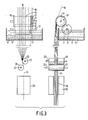
- Figure 3 is composed of two parts.
- the left-hand part of Figure 3 is a side elevation of the right-hand part which is a cross-sectional view of a device for carrying out the manufacturing method according to the invention.
- Reference numeral 9 in Figure 3 denotes a reservoir containing an ultraviolet light-curable lacquer composition 10. Examples of suitable lacquer compositions are recorded hereinbefore.
- a driving roller 11 on shaft 12 rotates in reservoir 9, roller 11 being immersed, for example half, in the liquid lacquer 10. The rate of rotation is by way of example 30 r.p.m. Parallel to driving roller 11 a lacquer roller 13 on shaft 14 is provided.
- the spacing betwe:en lacquer roller 13 and driving roller 11 is approximately 0.1 mm.
- Lacquer roller 13 hence is provided with a layer of lacquer, not shown via driving rollers 11.
- Lacquer roller 13 has two flanges 15. The surface of lacquer roller 13 provided with a layer of lacquer is present between the flanges 15. A flange 16 ensures that the part 17 of lacquer roller 13 does not comprise a layer of lacquer.
- Nine optical fibres 18 are guided over lacquer roller 13 at a speed of, for example, 40-70 metres per minute. The fibres, the outermost fibre 19 excepted, are consequently provided on one side with a layer of lacquer. The fibres are then guided over two guide rollers 20 and 21, respectively.
- the shafts 22, 23 of the guide rollers are at right angles to the shaft 14 of the lacquer roller 13.
Landscapes
- Physics & Mathematics (AREA)
- Engineering & Computer Science (AREA)
- Optics & Photonics (AREA)
- General Physics & Mathematics (AREA)
- Plasma & Fusion (AREA)
- Manufacturing & Machinery (AREA)
- Ophthalmology & Optometry (AREA)
- Mechanical Engineering (AREA)
- Health & Medical Sciences (AREA)
- Insulated Conductors (AREA)
- Optical Fibers, Optical Fiber Cores, And Optical Fiber Bundles (AREA)
- Surface Treatment Of Glass Fibres Or Filaments (AREA)
- Glass Compositions (AREA)
- Communication Cables (AREA)
- Extrusion Moulding Of Plastics Or The Like (AREA)
Abstract
Description
- The invention relates to an optical flat type cable in which several parallel extending optical fibres situated in a flat plane are bonded together.
- Such a cable is known from the German Offen- legungsschrift 27.24.536, page 3, first paragraph. It is stated that, although the cable has a good flexibility, it has on the other hand a low strength and breaks easily. It is suggested in the above-mentioned German Offen- legungsschrift to provide each fibre with a fixed or loose protecting cover and to provide thereon a cover of a soft synthetic resin. The fibres are interconnected via the cover of the soft synthetic resin. If desired, an adhesive may be used.
- The use of extra covers, such as that of the soft synthetic resin, causes the manufacture of the optical flat type cable to consume more time and effort and hence to become more expensive. Moreover, as a result of the extra covers, extra forces will also occur, for example, as a result of bending the cable or of temperature variations. As a result of this, an extra signal loss will occur.
- It is the object of the invention to provide an optical flat type cable in which the optical fibres supplied by the manufacturer and commercially available are processed directly, hence without (an) extra cover(s).
- Another object of the invention is to provide an optical flat type cable which is very flexible and moreover has a good mechanical strength.
- According to still another object an optical flat type cable is provided in which the signal loss of the optical fibres as a result of the processing to form a flat type cable, is extremely low.
- A further object of the invention is to provide an optical cable in which a number of optical flat type cables have been combined.
- Still a further object is to provide an efficacious, method of manufacturing an optical flat type cable.
- According to the invention these objects are achieved by means of an optical flat type cable of the type mentioned in the opening paragraph which is characterized in that the optical fibres are interconnected by a light-cured lacquer of acrylic acid esters which is present only on the facing circumferential parts of the optical fibres.
- The optical fibres in the cable according to the invention engage each other or engage each other substantially. This means thai/the spacing between the fibres is at most 10 /um.
- The lacquer of acrylic acid esters, prior to curing, comprises a mixture of mono-, di-, tri- and/or tetraesters of acrylic acid to which other light-curable ingredients such as N-vinylpyrrolidone may have been added. The lacquer comprises an initiator, for example, a benzoin isobutyl ether which is commercially available under the trade name Irgacure. Examples of useful acrylic acid esters are alkanediol acrylates, such as1,6-hexanediol diacrylate, alkene glycol diacrylates, such as tripropylene glycol diacrylate, trimethylol propane triacrylate, polyester acrylates, epoxy acrylate and urethane acrylate.
- The invention also relates to an optical cable which comprises a pack of a number of stacked optical flat type cables as described hereinbefore, which pack is twisted about its longitudinal axis and is surrounded by a loose tubular cover. The cover is usually a tube of a synthetic resin. The cover may comprise reinforcing elements, such as longitudinally extending reinforcing wires or reinforcing fibres, for example, polyaramide fibres, or steel wires, Further protective covers or an armouring may be provided around the cover. Several optical cables may also be grouped together and be provided with one or more common covers or a common armouring.
- The optical cable according to the invention excels by its simple construction and cheap method of manufacture and hence is very suitable for practical use on a large scale.
- The invention furthermore relates to method of manufacturing an optical flat type cable. The manufacturing method according to the invention is characterized in that a number of parallel extending optical fibres are guided over a first roller or system of rollers which at its surface has a layer of a light-curable lacquer in which the fibres, on passing over the roller, are provided on one side with a layer of lacquer, the fibres are then guided over a second roller or system of rollers the shaft of which is at right angles to that of the first roller or system of rollers, the fibres being rotated through an angle of 900 and the resulting assembly of optical fibres being exposed to light.
- The special aspect of the method according to the invention is that due to the rotation of the fibres through 900 the fibre bundle is self-calibrating. The fibres do the centring themselves, i.e. they automatically engage each other, the provided lacquer being present only between the facing circumferential parts of the fibres.
- So an important advantage of the method according to the invention is that no separate calibrating or centring device is necessary to get the fibres in their places, i.e. parallel against each other. Another inportant advantage is that the lacquer also lands in the correct place, i.e. only between the fibres.
- The invention will be described in greater detail with reference to the drawings, in which
- Figure 1 is a cross-sectional view of an optical flat type cable according to the invention,
- Figure 2 shows an optical cable according to the invention,
- Figure 3 shows diagrammatically a device for carrying out the method of manufacturing a flat type cable.
- Reference numeral 1 in Figure 1 denotes an optical fibre (glass fibre) as it is marketed by the manufacturer of optical fibres. The optical fibre always consists of a glass fibre 2 which has been provided by the manufacturer with a protective layer 3, the so-called primary coating, which is usually manufactured from U.V.-light-cured acrylates. The primary coating may consist of one or two layers. Without the primary coating, the optical fibre would be damaged very rapidly, so that the glass (optical) fibre, immediately after the manufacture thereof, is provided with the thin protective layer. The thickness of the primary coating is approximately 62 /um. The optical (glass) fibre has a diameter of 125 /um.
- The optical fibres are interconnected by a light-cured lacquer 4 of acrylic acid esters which is present only on the facing parts of the fibres 1. At the area of the lacquer 4 the fibres 1 engage each other or engage each other substantially. Examples of suitable lacquer compositions (prior to curing) are:
- a) 25% by weight of expoxyacrylate (75% by weight solution in tripropylene glycol diacrylate), 35% by weight of aromatic urethane acrylate, 16% by weight of tripropylene glycol diacrylate, 16% by weight of unsaturated tertiary amine (co-initiator) 8% by weight of benzophenone (initiator).
- b) 30% by weight of epoxyacrylate (75% solution in tripropylene glycol diacrylate), 40% by weight of aromatic urethane acrylate, 25% by weight of tripropylene glycol diacrylate, 1% by weight of ethanol 4% by weight of benzildimethyl ketal (initiator).
- c) 58% by weight of chlorinated polyester (60% solution in 1,6-hexanediol diacrylate) 38% by weight of semi-ester of phthalic acid and hydroxy. ethyl acrylate, 4% by weight of benzildimethyl ketal (initiator).
-
Reference numeral 5 in Figure 2 denotes a pack of eight stackedflat type cables 6. Each flat type cable is in conformity with Figure 1 with the proviso that sixoptical fibres 7 are incorporated in eachflat type cable 6. Thepack 5 is twisted about its longitudinal axis and is enveloped by a loosetubular cover 8.Cover 8 is manufactured, for example, from metal.Cover 8. is preferably manufactured from a synthetic resin which has been formed into a tube by means of an extrusion process. Thepack 5 is loose incover 8. The pack has a cross-section of, for example 2.5 x 2.5 mm and thecover 8 has an inside diameter of, for example, 6-10 mm. - Figure 3 is composed of two parts. The left-hand part of Figure 3 is a side elevation of the right-hand part which is a cross-sectional view of a device for carrying out the manufacturing method according to the invention.
Reference numeral 9 in Figure 3 denotes a reservoir containing an ultraviolet light-curable lacquer composition 10. Examples of suitable lacquer compositions are recorded hereinbefore. Adriving roller 11 onshaft 12 rotates inreservoir 9,roller 11 being immersed, for example half, in theliquid lacquer 10. The rate of rotation is by way of example 30 r.p.m. Parallel to driving roller 11 alacquer roller 13 onshaft 14 is provided. The spacing betwe:enlacquer roller 13 anddriving roller 11 is approximately 0.1 mm.Lacquer roller 13 hence is provided with a layer of lacquer, not shown viadriving rollers 11.Lacquer roller 13 has twoflanges 15. The surface oflacquer roller 13 provided with a layer of lacquer is present between theflanges 15. A flange 16 ensures that thepart 17 oflacquer roller 13 does not comprise a layer of lacquer. Nineoptical fibres 18 are guided overlacquer roller 13 at a speed of, for example, 40-70 metres per minute. The fibres, theoutermost fibre 19 excepted, are consequently provided on one side with a layer of lacquer. The fibres are then guided over twoguide rollers shafts shaft 14 of thelacquer roller 13. As a result of this the fibres are rotated through a quarter of a turn, the circumferential parts of the fibres provided with lacquer being made to face each other. The lacquer is now present between the fibres. It is furthermore achieved that the fibres do the centring themselves and will engage each other or will engage each other substantially. The bundle offibres 24 thus formed is then exposed to light, the bundle traversing anexposure zone 26 bounded by U.V.-lamps. As a result of this the lacquer is cured and a flat type cable similar to that shown in Figure 1 is obtained. The resulting flat type cable is extremely flexible, has a good mechanical rigidity and shows an extremely low signal loss with respect to the loose optical fibres (not processed to form a flat type cable) of 0.09 dB per km.
Claims (3)
Priority Applications (1)
| Application Number | Priority Date | Filing Date | Title |
|---|---|---|---|
| AT85200818T ATE67039T1 (en) | 1984-05-23 | 1985-05-22 | FLAT OPTICAL CABLE, PROCESS FOR MAKING THE SAME AND OPTICAL CABLE CONSISTING OF SEVERAL FLAT OPTICAL CABLES. |
Applications Claiming Priority (4)
| Application Number | Priority Date | Filing Date | Title |
|---|---|---|---|
| NL8401642 | 1984-05-23 | ||
| NL8401642 | 1984-05-23 | ||
| NL8403629A NL8403629A (en) | 1984-05-23 | 1984-11-29 | OPTICAL TAPE CABLE, METHOD FOR MANUFACTURING IT AND AN OPTICAL CABLE COMPOSED OF SEVERAL TAPE CABLES. |
| NL8403629 | 1984-11-29 |
Related Child Applications (2)
| Application Number | Title | Priority Date | Filing Date |
|---|---|---|---|
| EP87201544A Division EP0253457B1 (en) | 1984-05-23 | 1985-05-22 | Method of manufacturing an optical flat type cable |
| EP87201544A Division-Into EP0253457B1 (en) | 1984-05-23 | 1985-05-22 | Method of manufacturing an optical flat type cable |
Publications (3)
| Publication Number | Publication Date |
|---|---|
| EP0165632A2 true EP0165632A2 (en) | 1985-12-27 |
| EP0165632A3 EP0165632A3 (en) | 1986-01-02 |
| EP0165632B1 EP0165632B1 (en) | 1991-09-04 |
Family
ID=26645954
Family Applications (2)
| Application Number | Title | Priority Date | Filing Date |
|---|---|---|---|
| EP85200818A Expired - Lifetime EP0165632B1 (en) | 1984-05-23 | 1985-05-22 | Optical flat type cable, method of manufacturing same, and an optical cable composed of several flat type cables |
| EP87201544A Expired - Lifetime EP0253457B1 (en) | 1984-05-23 | 1985-05-22 | Method of manufacturing an optical flat type cable |
Family Applications After (1)
| Application Number | Title | Priority Date | Filing Date |
|---|---|---|---|
| EP87201544A Expired - Lifetime EP0253457B1 (en) | 1984-05-23 | 1985-05-22 | Method of manufacturing an optical flat type cable |
Country Status (8)
| Country | Link |
|---|---|
| US (2) | US4666244A (en) |
| EP (2) | EP0165632B1 (en) |
| JP (1) | JPS60257415A (en) |
| KR (1) | KR920009188B1 (en) |
| AT (2) | ATE67039T1 (en) |
| BR (1) | BR8502435A (en) |
| DE (2) | DE3583944D1 (en) |
| NL (1) | NL8403629A (en) |
Cited By (12)
| Publication number | Priority date | Publication date | Assignee | Title |
|---|---|---|---|---|
| GB2184563A (en) * | 1985-12-23 | 1987-06-24 | Telephone Cables Ltd | Optical fibre units |
| GB2215084A (en) * | 1988-02-23 | 1989-09-13 | Stc Plc | Optical fibre ribbon containing cables |
| EP0330277A3 (en) * | 1988-02-26 | 1990-04-04 | Philips Patentverwaltung GmbH | Apparatus for glueing a plurality of optical wave guides to a ribbon structure |
| EP0327164A3 (en) * | 1988-02-01 | 1990-05-09 | Philips Patentverwaltung | Method of producing an optical cable |
| US4980012A (en) * | 1989-07-24 | 1990-12-25 | Mitsubishi Rayon Company Ltd | Apparatus for preparation of a sheet-shaped photoconductor |
| WO1991000536A1 (en) | 1989-06-28 | 1991-01-10 | Siemens Aktiengesellschaft | Fibre-optic cable with at least one optical fibre |
| DE3926593A1 (en) * | 1989-08-11 | 1991-02-14 | Rheydt Kabelwerk Ag | OPTICAL CABLE |
| EP0357139A3 (en) * | 1988-08-31 | 1991-07-17 | Philips Patentverwaltung GmbH | Optical wave guide ribbon cable production method |
| GB2271859A (en) * | 1992-10-21 | 1994-04-27 | Northern Telecom Ltd | Optical fibre cable comprising stack of ribbon fibre elements |
| DE4324574A1 (en) * | 1992-12-16 | 1994-06-23 | Rheydt Kabelwerk Ag | Optical cable |
| US5761361A (en) * | 1995-05-10 | 1998-06-02 | Siemens Aktiengesellschaft | Elongated optical transmission element |
| EP1235087A3 (en) * | 2000-12-27 | 2004-02-04 | CCS Technology, Inc. | Fiber optic cable assembly and method of making same |
Families Citing this family (25)
| Publication number | Priority date | Publication date | Assignee | Title |
|---|---|---|---|---|
| JPH0833507B2 (en) * | 1986-12-24 | 1996-03-29 | 三菱電線工業株式会社 | Tape-type optical fiber manufacturing equipment |
| US5259055A (en) * | 1988-05-23 | 1993-11-02 | The United States Of America As Represented By The Secrtary Of The Navy | Fiber optic microcable produced with radiation cured composite |
| US5593736A (en) * | 1988-05-26 | 1997-01-14 | The United States Of America As Represented By The Secretary Of The Navy | Process for manufacturing a fiber reinforced optic microcable with a UV cured resin |
| US4900126A (en) * | 1988-06-30 | 1990-02-13 | American Telephone & Telegraph Co. | Bonded array of transmission media |
| JPH0279008A (en) * | 1988-09-14 | 1990-03-19 | Furukawa Electric Co Ltd:The | Production of optical fiber cable |
| FR2651353B1 (en) * | 1989-08-31 | 1993-12-17 | Pascal Auroy | DIDACTIC STOMATIC MODEL. |
| US5013127A (en) * | 1990-04-26 | 1991-05-07 | Siecor Corporation | Flexible fiber optic distribution cable |
| US5207857A (en) * | 1990-05-29 | 1993-05-04 | The Furukawa Electric Co., Ltd. | Forced aligning jig for loose wires |
| US5080838A (en) * | 1990-08-10 | 1992-01-14 | U.S. Philips Corp. | Method of producing an optical cable |
| US5202945A (en) * | 1991-02-06 | 1993-04-13 | Siemens Aktiengesellschaft | Optical cable and method for the manufacture thereof |
| CA2129397C (en) * | 1993-12-21 | 2005-03-22 | Mujibar M. Rahman | Process for manufacturing optical fiber ribbons |
| US6052503A (en) * | 1995-09-07 | 2000-04-18 | Dsm N.V. | Optical glass fiber ribbon assembly and radiation curable matrix forming composition |
| US5768460A (en) * | 1995-10-03 | 1998-06-16 | Siecor Corporation | Low skew optical fiber ribbons |
| US6002824A (en) * | 1996-02-13 | 1999-12-14 | Alcatel | Fiber optic cable without reinforcing members |
| FR2744809B1 (en) * | 1996-02-13 | 1998-03-13 | Alcatel Cable | OPTICAL FIBER CABLE WITHOUT REINFORCING ELEMENTS |
| US5787217A (en) * | 1996-02-15 | 1998-07-28 | Simplex Technologies, Inc. | Fiber optic ground wire cable |
| US5649755A (en) * | 1996-02-20 | 1997-07-22 | Rapisarda; Carmen C. | Elongated, decorative, flexible, light-transmitting assembly |
| US6018605A (en) * | 1997-12-31 | 2000-01-25 | Siecor Operations | Photoinitiator--tuned optical fiber and optical fiber ribbon and method of making the same |
| US5995693A (en) * | 1998-07-02 | 1999-11-30 | Alcatel | Method of making an optical fiber ribbon with improved planarity and an optical fiber ribbon with improved planarity |
| KR100322123B1 (en) | 1998-11-18 | 2002-03-08 | 윤종용 | Optical fiber composite ground wire having steel tube |
| US6483972B1 (en) | 2000-04-06 | 2002-11-19 | Alcatel | Edge-bonded splittable optical-fiber ribbon |
| JP4183991B2 (en) * | 2002-07-12 | 2008-11-19 | シーシーエス株式会社 | Optical fiber holding device and optical fiber holding method |
| WO2004042446A1 (en) * | 2002-11-06 | 2004-05-21 | Sumitomo Electric Industries, Ltd. | Optical fiber ribbon and optical fiber cable using the same |
| CA2871108C (en) | 2012-05-02 | 2019-09-17 | Afl Telecommunications Llc | Round and small diameter optical cables with a ribbon-like optical fiber structure |
| US20230168441A1 (en) * | 2021-11-30 | 2023-06-01 | Corning Research & Development Corporation | Unjacketed fiber optic cable assembly, and cable assembly including connector with travel limited ferrule |
Family Cites Families (23)
| Publication number | Priority date | Publication date | Assignee | Title |
|---|---|---|---|---|
| AT245755B (en) * | 1963-05-31 | 1966-03-10 | Christian Heinrich Turcksin | Elastically stretchable tape in longitudinal and transverse directions and process for its production |
| US3486962A (en) * | 1966-04-06 | 1969-12-30 | Goodyear Tire & Rubber | Reinforced rubber bands,etc. |
| DE1572857A1 (en) * | 1967-08-25 | 1970-03-05 | Jos. Schneider & Co, Optische Werke, 6550 Bad Kreuznach | Ribbon-shaped, fiber-optic component and method for its production |
| US3602416A (en) * | 1969-01-29 | 1971-08-31 | United Aircraft Corp | Method of collimating fibers |
| US3736217A (en) * | 1969-09-29 | 1973-05-29 | American Optical Corp | Light-conducting fiber material |
| GB1518082A (en) * | 1974-06-28 | 1978-07-19 | Post Office | Methods and apparatus for covering filaments |
| GB1570624A (en) * | 1975-12-11 | 1980-07-02 | Western Electric Co | Optical fibre transmission arrangements |
| DE2606777A1 (en) * | 1976-02-19 | 1977-09-01 | Siemens Ag | RIBBON OR FLAT CABLES |
| DE2724536A1 (en) * | 1977-05-31 | 1978-12-14 | Siemens Ag | RIBBON OR FLAT CABLES WITH OPTICAL TRANSMISSION ELEMENTS |
| DE2744129A1 (en) * | 1977-09-30 | 1979-04-12 | Siemens Ag | CORE-COAT GLASS FIBER WITH LATERAL COUPLING AREA |
| JPS6057568B2 (en) * | 1978-07-07 | 1985-12-16 | 古河電気工業株式会社 | Manufacturing method of optical fiber tape |
| US4269024A (en) * | 1978-08-01 | 1981-05-26 | Associated Electrical Industries Limited | Strength members for the reinforcement of optical fibre cables |
| JPS5654403A (en) * | 1979-10-11 | 1981-05-14 | Nippon Telegr & Teleph Corp <Ntt> | Optical fiber cable |
| NL7908966A (en) * | 1979-12-13 | 1981-07-16 | Philips Nv | OPTICAL TELECOMMUNICATIONS ELEMENT, METHOD FOR MANUFACTURING IT AND OPTICAL TELECOMMUNICATIONS CABLE FITTED WITH THE ELEMENT. |
| JPS5789710A (en) * | 1980-11-26 | 1982-06-04 | Furukawa Electric Co Ltd:The | Reinforced ribbon optical fiber |
| US4859023A (en) * | 1981-09-21 | 1989-08-22 | American Telephone And Telegraph Company, At&T Bell Laboratories | Sheathed optical fiber cable |
| DE3144205A1 (en) * | 1981-11-06 | 1983-05-19 | Siemens AG, 1000 Berlin und 8000 München | Optical fibre cable for a distribution network constructed in the form of a star |
| JPS58196218A (en) * | 1982-05-11 | 1983-11-15 | Daikin Ind Ltd | Copolymer for optical fiber |
| GB2127578B (en) * | 1982-09-23 | 1985-09-04 | Bicc Plc | Am improved optical fibre ribbon structure |
| US4472019A (en) * | 1982-12-28 | 1984-09-18 | Desoto, Inc. | Topcoats for buffer-coated optical fiber using urethane acrylate and epoxy acrylate and vinyl monomer |
| JPS59228204A (en) * | 1983-06-09 | 1984-12-21 | Nippon Telegr & Teleph Corp <Ntt> | Tapelike optical fiber and its manufacture |
| US4547040A (en) * | 1983-06-21 | 1985-10-15 | Mitsubishi Rayon Co., Ltd. | Optical fiber assembly and process for preparing same |
| EP0131058B1 (en) * | 1983-06-22 | 1988-01-27 | Mitsubishi Rayon Co., Ltd. | Optical fiber assembly and process for preparing same |
-
1984
- 1984-11-29 NL NL8403629A patent/NL8403629A/en not_active Application Discontinuation
-
1985
- 1985-05-22 EP EP85200818A patent/EP0165632B1/en not_active Expired - Lifetime
- 1985-05-22 DE DE8787201544T patent/DE3583944D1/en not_active Expired - Lifetime
- 1985-05-22 EP EP87201544A patent/EP0253457B1/en not_active Expired - Lifetime
- 1985-05-22 DE DE8585200818T patent/DE3583971D1/en not_active Expired - Lifetime
- 1985-05-22 AT AT85200818T patent/ATE67039T1/en not_active IP Right Cessation
- 1985-05-22 AT AT87201544T patent/ATE66754T1/en not_active IP Right Cessation
- 1985-05-23 JP JP60109459A patent/JPS60257415A/en active Granted
- 1985-05-23 KR KR1019850003640A patent/KR920009188B1/en not_active Expired
- 1985-05-23 BR BR8502435A patent/BR8502435A/en not_active IP Right Cessation
- 1985-05-23 US US06/737,294 patent/US4666244A/en not_active Expired - Lifetime
-
1986
- 1986-12-05 US US06/938,473 patent/US4724024A/en not_active Expired - Fee Related
Cited By (15)
| Publication number | Priority date | Publication date | Assignee | Title |
|---|---|---|---|---|
| GB2184563A (en) * | 1985-12-23 | 1987-06-24 | Telephone Cables Ltd | Optical fibre units |
| EP0327164A3 (en) * | 1988-02-01 | 1990-05-09 | Philips Patentverwaltung | Method of producing an optical cable |
| GB2215084A (en) * | 1988-02-23 | 1989-09-13 | Stc Plc | Optical fibre ribbon containing cables |
| EP0330277A3 (en) * | 1988-02-26 | 1990-04-04 | Philips Patentverwaltung GmbH | Apparatus for glueing a plurality of optical wave guides to a ribbon structure |
| EP0357139A3 (en) * | 1988-08-31 | 1991-07-17 | Philips Patentverwaltung GmbH | Optical wave guide ribbon cable production method |
| US5163116A (en) * | 1989-06-28 | 1992-11-10 | Siemens Aktiengesellschaft | Optical cable with at least one optical waveguide |
| WO1991000536A1 (en) | 1989-06-28 | 1991-01-10 | Siemens Aktiengesellschaft | Fibre-optic cable with at least one optical fibre |
| EP0410023A1 (en) * | 1989-07-24 | 1991-01-30 | Mitsubishi Rayon Co., Ltd | Process and apparatus for preparation of an optical fiber ribbon |
| US4980012A (en) * | 1989-07-24 | 1990-12-25 | Mitsubishi Rayon Company Ltd | Apparatus for preparation of a sheet-shaped photoconductor |
| DE3926593A1 (en) * | 1989-08-11 | 1991-02-14 | Rheydt Kabelwerk Ag | OPTICAL CABLE |
| GB2271859A (en) * | 1992-10-21 | 1994-04-27 | Northern Telecom Ltd | Optical fibre cable comprising stack of ribbon fibre elements |
| GB2271859B (en) * | 1992-10-21 | 1995-10-18 | Northern Telecom Ltd | Optical fibre cable comprising stack of ribbon fibre elements |
| DE4324574A1 (en) * | 1992-12-16 | 1994-06-23 | Rheydt Kabelwerk Ag | Optical cable |
| US5761361A (en) * | 1995-05-10 | 1998-06-02 | Siemens Aktiengesellschaft | Elongated optical transmission element |
| EP1235087A3 (en) * | 2000-12-27 | 2004-02-04 | CCS Technology, Inc. | Fiber optic cable assembly and method of making same |
Also Published As
| Publication number | Publication date |
|---|---|
| EP0253457A2 (en) | 1988-01-20 |
| KR920009188B1 (en) | 1992-10-14 |
| EP0253457A3 (en) | 1988-10-12 |
| BR8502435A (en) | 1986-01-28 |
| US4724024A (en) | 1988-02-09 |
| EP0253457B1 (en) | 1991-08-28 |
| EP0165632A3 (en) | 1986-01-02 |
| ATE67039T1 (en) | 1991-09-15 |
| EP0165632B1 (en) | 1991-09-04 |
| DE3583971D1 (en) | 1991-10-10 |
| US4666244A (en) | 1987-05-19 |
| DE3583944D1 (en) | 1991-10-02 |
| KR850008721A (en) | 1985-12-21 |
| JPS60257415A (en) | 1985-12-19 |
| JPH0569205B2 (en) | 1993-09-30 |
| ATE66754T1 (en) | 1991-09-15 |
| NL8403629A (en) | 1985-12-16 |
Similar Documents
| Publication | Publication Date | Title |
|---|---|---|
| EP0165632A2 (en) | Optical flat type cable, method of manufacturing same, and an optical cable composed of several flat type cables | |
| EP0922980B1 (en) | Bonded array of transmission media | |
| JP3001117B2 (en) | Optical cable and its manufacturing method | |
| US5373578A (en) | Strippable coating for optical fiber | |
| EP0194891A1 (en) | Optical fibre assemblies and optical fibre cables | |
| US4690503A (en) | Glass optical fiber having a primary and a secondary coating | |
| JP4055000B2 (en) | Optical fiber cable, optical fiber cable manufacturing method, and optical fiber cable manufacturing apparatus | |
| US5751880A (en) | Optical unit for an optical fiber telecommunications cable, and an optical fiber cable including such a unit | |
| WO2004092778A2 (en) | Optical fiber ribbons having a preferential separation sequence | |
| US6853783B2 (en) | Optical Fiber Ribbons Having Preferential Tear Portions | |
| JPS592881B2 (en) | optical fiber ribbon | |
| EP0210770B2 (en) | Plastics packaged optical fibres | |
| JP2950264B2 (en) | Manufacturing method of optical fiber ribbon | |
| KR20000028784A (en) | Coated optical fiber with improved strippability | |
| US4565593A (en) | Connection and inspection of optical fibres by fusion splicing | |
| WO2001063332A1 (en) | Optical transmission element, process as well as device for its manufacture | |
| JPH01150106A (en) | Tape-shaped optical fiber | |
| JP3008863B2 (en) | Optical fiber unit | |
| JP2925099B2 (en) | Optical fiber core and tape type optical fiber core | |
| CN1005654B (en) | Optical flat cable, method for manufacturing the same, and optical cable composed of a plurality of flat cables | |
| JPH095592A (en) | Optical fiber cord | |
| JP2002116358A (en) | Coated optical fiber tape and method for producing the same | |
| JPH0749447Y2 (en) | Optical fiber tape core | |
| DE3530963A1 (en) | Splice guard for a glass optical fibre | |
| JPS60153014A (en) | Optical fiber unit |
Legal Events
| Date | Code | Title | Description |
|---|---|---|---|
| PUAI | Public reference made under article 153(3) epc to a published international application that has entered the european phase |
Free format text: ORIGINAL CODE: 0009012 |
|
| PUAL | Search report despatched |
Free format text: ORIGINAL CODE: 0009013 |
|
| AK | Designated contracting states |
Designated state(s): AT DE FR GB IT NL SE |
|
| AK | Designated contracting states |
Designated state(s): AT DE FR GB IT NL SE |
|
| 17P | Request for examination filed |
Effective date: 19860604 |
|
| 17Q | First examination report despatched |
Effective date: 19870220 |
|
| GRAA | (expected) grant |
Free format text: ORIGINAL CODE: 0009210 |
|
| AK | Designated contracting states |
Kind code of ref document: B1 Designated state(s): AT DE FR GB IT NL SE |
|
| REF | Corresponds to: |
Ref document number: 67039 Country of ref document: AT Date of ref document: 19910915 Kind code of ref document: T |
|
| REF | Corresponds to: |
Ref document number: 3583971 Country of ref document: DE Date of ref document: 19911010 |
|
| ITF | It: translation for a ep patent filed | ||
| ET | Fr: translation filed | ||
| PLBE | No opposition filed within time limit |
Free format text: ORIGINAL CODE: 0009261 |
|
| STAA | Information on the status of an ep patent application or granted ep patent |
Free format text: STATUS: NO OPPOSITION FILED WITHIN TIME LIMIT |
|
| 26N | No opposition filed | ||
| PGFP | Annual fee paid to national office [announced via postgrant information from national office to epo] |
Ref country code: NL Payment date: 19930531 Year of fee payment: 9 |
|
| PG25 | Lapsed in a contracting state [announced via postgrant information from national office to epo] |
Ref country code: NL Effective date: 19941201 |
|
| NLV4 | Nl: lapsed or anulled due to non-payment of the annual fee | ||
| EAL | Se: european patent in force in sweden |
Ref document number: 85200818.4 |
|
| ITPR | It: changes in ownership of a european patent |
Owner name: CAMBIO RAGIONE SOCIALE;PHILIPS ELECTRONICS N.V. |
|
| REG | Reference to a national code |
Ref country code: FR Ref legal event code: CD |
|
| REG | Reference to a national code |
Ref country code: GB Ref legal event code: 732E |
|
| PGFP | Annual fee paid to national office [announced via postgrant information from national office to epo] |
Ref country code: AT Payment date: 19990422 Year of fee payment: 15 |
|
| PG25 | Lapsed in a contracting state [announced via postgrant information from national office to epo] |
Ref country code: AT Free format text: LAPSE BECAUSE OF NON-PAYMENT OF DUE FEES Effective date: 20000522 |
|
| PGFP | Annual fee paid to national office [announced via postgrant information from national office to epo] |
Ref country code: SE Payment date: 20010503 Year of fee payment: 17 |
|
| REG | Reference to a national code |
Ref country code: GB Ref legal event code: IF02 |
|
| PG25 | Lapsed in a contracting state [announced via postgrant information from national office to epo] |
Ref country code: SE Free format text: LAPSE BECAUSE OF NON-PAYMENT OF DUE FEES Effective date: 20020523 |
|
| EUG | Se: european patent has lapsed | ||
| PGFP | Annual fee paid to national office [announced via postgrant information from national office to epo] |
Ref country code: GB Payment date: 20040504 Year of fee payment: 20 |
|
| PGFP | Annual fee paid to national office [announced via postgrant information from national office to epo] |
Ref country code: DE Payment date: 20040517 Year of fee payment: 20 |
|
| PGFP | Annual fee paid to national office [announced via postgrant information from national office to epo] |
Ref country code: FR Payment date: 20040524 Year of fee payment: 20 |
|
| PG25 | Lapsed in a contracting state [announced via postgrant information from national office to epo] |
Ref country code: GB Free format text: LAPSE BECAUSE OF EXPIRATION OF PROTECTION Effective date: 20050521 |
|
| REG | Reference to a national code |
Ref country code: GB Ref legal event code: PE20 |