EP0165635B1 - Gelenk mit mehreren Freiheitsgraden - Google Patents
Gelenk mit mehreren Freiheitsgraden Download PDFInfo
- Publication number
- EP0165635B1 EP0165635B1 EP85200867A EP85200867A EP0165635B1 EP 0165635 B1 EP0165635 B1 EP 0165635B1 EP 85200867 A EP85200867 A EP 85200867A EP 85200867 A EP85200867 A EP 85200867A EP 0165635 B1 EP0165635 B1 EP 0165635B1
- Authority
- EP
- European Patent Office
- Prior art keywords
- flexible
- bellows
- jacks
- linked
- signals
- Prior art date
- Legal status (The legal status is an assumption and is not a legal conclusion. Google has not performed a legal analysis and makes no representation as to the accuracy of the status listed.)
- Expired
Links
Images

Classifications
-
- B—PERFORMING OPERATIONS; TRANSPORTING
- B25—HAND TOOLS; PORTABLE POWER-DRIVEN TOOLS; MANIPULATORS
- B25J—MANIPULATORS; CHAMBERS PROVIDED WITH MANIPULATION DEVICES
- B25J17/00—Joints
- B25J17/02—Wrist joints
- B25J17/0258—Two-dimensional joints
- B25J17/0266—Two-dimensional joints comprising more than two actuating or connecting rods
-
- B—PERFORMING OPERATIONS; TRANSPORTING
- B25—HAND TOOLS; PORTABLE POWER-DRIVEN TOOLS; MANIPULATORS
- B25J—MANIPULATORS; CHAMBERS PROVIDED WITH MANIPULATION DEVICES
- B25J3/00—Manipulators of leader-follower type, i.e. both controlling unit and controlled unit perform corresponding spatial movements
- B25J3/04—Manipulators of leader-follower type, i.e. both controlling unit and controlled unit perform corresponding spatial movements involving servo mechanisms
-
- B—PERFORMING OPERATIONS; TRANSPORTING
- B25—HAND TOOLS; PORTABLE POWER-DRIVEN TOOLS; MANIPULATORS
- B25J—MANIPULATORS; CHAMBERS PROVIDED WITH MANIPULATION DEVICES
- B25J9/00—Program-controlled manipulators
- B25J9/003—Program-controlled manipulators having parallel kinematics
- B25J9/0075—Truss
-
- B—PERFORMING OPERATIONS; TRANSPORTING
- B25—HAND TOOLS; PORTABLE POWER-DRIVEN TOOLS; MANIPULATORS
- B25J—MANIPULATORS; CHAMBERS PROVIDED WITH MANIPULATION DEVICES
- B25J9/00—Program-controlled manipulators
- B25J9/06—Program-controlled manipulators characterised by multi-articulated arms
-
- B—PERFORMING OPERATIONS; TRANSPORTING
- B25—HAND TOOLS; PORTABLE POWER-DRIVEN TOOLS; MANIPULATORS
- B25J—MANIPULATORS; CHAMBERS PROVIDED WITH MANIPULATION DEVICES
- B25J9/00—Program-controlled manipulators
- B25J9/10—Program-controlled manipulators characterised by positioning means for manipulator elements
- B25J9/14—Program-controlled manipulators characterised by positioning means for manipulator elements fluid
Definitions
- the invention relates to a mobile connection device between a carrier element and a carried element. It is applicable in the robotics sector to make manipulation arms.
- the present invention relates to improvements to this type of device.
- An objective of the invention is in particular to provide a device in which any movement takes place under the action of hydraulic compression with a view to eliminating the power limitations which condition the appearance of cavitation phenomena in the systems in depression.
- Another objective is to authorize precise movements not affected by parasitic deformations of the various flexible organs of the system (connecting duct, bellows) or by the compressibility of the fluid used (generally a liquid to limit this compressibility).
- such a device arranged in a closed loop operates in a differential mode both at the level of the actuator means (flexible cylinders) as well as control means thereof (tanks of variable capacity, motor means and means measurement). It is thus possible to obtain very precise displacements of the worn element, which are not influenced by any parasitic phenomenon; in addition, each movement is carried out by hydraulic compression in one of the two associated jacks, so that cavitation phenomena which could appear beyond a certain power are totally excluded.
- connection device targeted by the invention may have various arrangements in order to produce a handling system depending on the envisaged application.
- This connecting device comprises several cylinders associated two by two which are controlled by tanks of variable capacity, themselves associated two by two, so that each pair of associated cylinders forms with each pair of associated tanks a closed loop differential system .
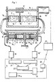
- Figure 1 there is shown a pair of associated cylinders, the corresponding tanks and an electronic processing unit 5 ensuring the control of the system.
- the jacks 1 and 2 are constituted by two bellows 1a or 2a each secured on two rigid walls 1b, 1c or 2b, 2c.
- the bellows 1a, 2a extend along the same axis, on either side of an intermediate rigid wall 6 which is secured between the walls 1c and 2c and is integral with a frame 7.
- the other walls 1 and 2b are traversed by fluid conduits 8 and 9 and are in the example integral with a member 10.
- the jacks 1 and 2 thus make it possible to move the member 7 relative to the member 10; these members constitute the intermediate members which can be arranged with other pairs of jacks, in accordance with the examples described in patent application EP-A-113 145 already mentioned or according to any other arrangement suitable for the intended application.
- each pair of jacks 1 and 2 of the device is arranged so that the centers of the two walls 1b, 1c or 2b, 2c which delimit each jack, are constantly positioned on the common axis of the bellows 1a and 2a; this can be obtained by means of guides such as 11, which guide the movement of the walls of the jacks in a translational movement parallel to the axis.
- each cylinder is provided with an ultrasonic transceiver 12 disposed in each bellows on the axis thereof in a fixed position relative to one of the two walls (1b), so as to be able to transmit in the direction from the center of the other wall (1c); this transceiver is associated with electronic means 13 or 13 ′ (such as a bistable circuit) adapted to deliver an electrical signal representative of the time separating a transmission from the reception of the corresponding echo.
- electronic means 13 or 13 ′ such as a bistable circuit
- Such measurement means making it possible to know at all times the state of deformation of the jack in question are known in themselves and may in particular comprise a quartz pellet associated with means of impulse excitation at its natural frequency, reception being ensured in the example covered by the same pellet.
- the time which separates a transmission from the reception of its echo is representative of twice the distance separating the patch 12 and the wall 1c - and therefore of the state of deformation of the jack along its axis.
- the two cylinders 1 and 2 are hydraulically connected by the conduits 8 and 9 to the tanks of variable capacity 3 and 4.
- These tanks consist of two bellows 3a, 4a extending along the same axis between two fixed walls 14 and 15 carried by a frame and traversed by the fluid conduits 8 and 9.
- the bellows 3a and 4a are separated by an intermediate wall 16 movable along the axis of the bellows and linked to motor means in order to cause its movement along this axis.
- the intermediate wall 16 is subject to a threaded socket 17 carried by an endless screw 18 parallel to the axis of the bellows.
- An electric gear motor 19 powered by a power circuit 20 allows the screw 18 to rotate in one direction or the other.
- the two electrical signals from the measuring means (12, 13) which are associated with each pair of jacks (1, 2) are processed by the unit 5.
- Each of the two signals is delivered to a sampling circuit 21 or 22 , which generates a series of pulses whose number proportional to the duration of the initial signal is representative of the state of deformation of the jack considered.
- the pulses from circuits 21 and 22 are sent to a differentiator 23 which supplies a differential digital signal, representative of the difference in the number of pulses between the two signals from the sampling circuits.
- This digital signal is representative of the state of the differential system constituted by the two jacks 1 and 2.
- This digital signal is sent to a comparison unit 24 comprising digital counters and also receiving a digital reference signal from a generation unit (25a); the latter is adapted to deliver digital reference signals corresponding to the desired deformation states of the cylinders 1 and 2.
- the comparison unit 24 delivers a digital error signal to a digital / analog converter 25; after conversion, the signal is amplified and controls the power circuit 20 which supplies the gear motor 19; the rotation of the latter is controlled in the direction tending to cancel the control signal.
- a microprocessor which will generate the setpoint signals through appropriate programming and will control all of the motors 19 associated with all of the pairs of tanks 3, 4 as a function of these signals. setpoint and measurement signals.
- Figure 2 shows schematically a variant of the device.
- the reservoirs of variable capacity and the processing unit are similar to the previous embodiment and have not been shown.
- the flexible jacks 26 and 27 are paired so as to rotate a first rigid member such as 28 relative to a second rigid member such as 29.
- paired jacks are actuated as before in a differential mode so as to undergo opposite deformations.
- Each cylinder is constituted by a bellows such as 26a secured on two rigid walls 26b and 26c.
- the wall 26b is fixed to the frame 28 and is crossed by the hydraulic conduit.
- the wall 26c carries a rolling ball bearing against the frame 29.
- the jacks 26 and 27 are, moreover, provided with measuring means of the same type as above, capable of delivering an electrical signal representative of their state of deformation.
- the two members 28 and 29 are connected by a spacer 30 fixed on the mem brure 28 and articulated on the frame 29 by means of a ball joint 30a.
- the state of deformation of the cylinders 26 and 27 controls the angle of inclination of the member 29 relative to the member 28, in the plane of the two cylinders.
- a similar system of two associated jacks can be provided in an orthogonal plane in order to control the inclination of the two members in this plane. It is thus possible to tilt the frame 29 around its articulation in all directions of space with an amplitude which depends on the stroke of the jacks.
Landscapes
- Engineering & Computer Science (AREA)
- Robotics (AREA)
- Mechanical Engineering (AREA)
- Manipulator (AREA)
- Actuator (AREA)
- Control Of Position Or Direction (AREA)
- Reciprocating Pumps (AREA)
Claims (9)
Applications Claiming Priority (2)
| Application Number | Priority Date | Filing Date | Title |
|---|---|---|---|
| FR8409927A FR2565882B2 (fr) | 1984-06-13 | 1984-06-13 | Dispositif de liaison a plusieurs degres de liberte |
| FR8409927 | 1984-06-13 |
Publications (2)
| Publication Number | Publication Date |
|---|---|
| EP0165635A1 EP0165635A1 (de) | 1985-12-27 |
| EP0165635B1 true EP0165635B1 (de) | 1988-04-13 |
Family
ID=9305360
Family Applications (1)
| Application Number | Title | Priority Date | Filing Date |
|---|---|---|---|
| EP85200867A Expired EP0165635B1 (de) | 1984-06-13 | 1985-05-31 | Gelenk mit mehreren Freiheitsgraden |
Country Status (5)
| Country | Link |
|---|---|
| US (1) | US4800723A (de) |
| EP (1) | EP0165635B1 (de) |
| JP (1) | JPS614689A (de) |
| DE (1) | DE3562121D1 (de) |
| FR (1) | FR2565882B2 (de) |
Families Citing this family (12)
| Publication number | Priority date | Publication date | Assignee | Title |
|---|---|---|---|---|
| NL8700307A (nl) * | 1987-02-10 | 1988-09-01 | Berend Jan Bloemendal | Door een stroombaar medium te bedienen duwbalk alsmede een als hulpmiddel bij het laden en lossen te gebruiken inrichting, voorzien van een of meer van dergelijke duwbalken. |
| JPH0627477Y2 (ja) * | 1988-07-14 | 1994-07-27 | 株式会社小糸製作所 | 車輌用前照灯の照射角度調整装置 |
| FR2672836B1 (fr) * | 1991-02-15 | 1995-06-02 | Onera (Off Nat Aerospatiale) | Dispositif d'articulation a structure parallele et appareils de transmission de mouvement a distance en faisant application. |
| JP3331152B2 (ja) * | 1997-07-29 | 2002-10-07 | 東芝機械株式会社 | 密閉液圧式増圧装置 |
| US8065951B2 (en) * | 2005-02-15 | 2011-11-29 | P.I. Engineering, Inc. | Servo-controlled tipping platform and motion control system therefor |
| DE102008050519B4 (de) * | 2008-10-06 | 2021-07-01 | Ferrobotics Compliant Robot Technology Gmbh | Schwenkbarer Flansch |
| FR2997888B1 (fr) | 2012-11-14 | 2015-08-21 | Commissariat Energie Atomique | Bras articule |
| FR2997887B1 (fr) * | 2012-11-14 | 2015-07-10 | Commissariat Energie Atomique | Systeme hexapode |
| JP2015036161A (ja) * | 2013-08-12 | 2015-02-23 | 国立大学法人富山大学 | 関節機構 |
| US9611740B2 (en) * | 2013-11-22 | 2017-04-04 | L & B Manufacturing, Inc. | Pneumatic actuators |
| US10786910B2 (en) * | 2017-08-21 | 2020-09-29 | Massachusetts Institute Of Technology | Extending robotic arm |
| US12129876B2 (en) * | 2022-04-05 | 2024-10-29 | Arizona Board Of Regents On Behalf Of Arizona State University | Bistable elastomeric actuator |
Family Cites Families (34)
| Publication number | Priority date | Publication date | Assignee | Title |
|---|---|---|---|---|
| US1256127A (en) * | 1916-08-10 | 1918-02-12 | A E Kibble | Pump. |
| US1289435A (en) * | 1916-09-15 | 1918-12-31 | Fulton Co | Heat-motor. |
| US1543061A (en) * | 1920-05-18 | 1925-06-23 | Oscar A Danielson | Balanced transmission for distant indicators |
| US2124735A (en) * | 1935-05-20 | 1938-07-26 | Automotive Devices Inc | Fluid pressure motor |
| US2325967A (en) * | 1939-10-24 | 1943-08-03 | Brown Instr Co | Air control instrument |
| US2496729A (en) * | 1941-11-29 | 1950-02-07 | Bendix Aviat Corp | Fluid pressure control |
| US2578265A (en) * | 1948-10-11 | 1951-12-11 | Milton Roy Co | Bellows pump |
| US2909315A (en) * | 1956-10-10 | 1959-10-20 | Thompson Ramo Wooldridge Inc | Hydraulically operated gas compressor |
| US3095532A (en) * | 1959-06-29 | 1963-06-25 | Peter G Floyd | Vibration responsive system for stopping motor driven machines |
| US3279624A (en) * | 1962-09-26 | 1966-10-18 | George C Devol | Programmed article handling |
| US3309588A (en) * | 1963-12-05 | 1967-03-14 | Ferranti Ltd | Multiplex servo system for servo motors mechanically connected in series |
| US3284964A (en) * | 1964-03-26 | 1966-11-15 | Saito Norio | Flexible beam structures |
| US3401607A (en) * | 1966-08-08 | 1968-09-17 | Michael L. Wortman | Reciprocating bellows |
| US3449008A (en) * | 1967-06-08 | 1969-06-10 | Gen Dynamics Corp | Object handling system with remote manual control |
| JPS5321073B2 (de) * | 1973-01-31 | 1978-06-30 | ||
| DE2355966A1 (de) * | 1973-11-09 | 1975-05-22 | Medac Klinische Spezialpraep | Pumpenanordnung, insbesondere fuer blutpumpen |
| FR2416365A1 (fr) * | 1978-02-02 | 1979-08-31 | Meca Acoustique Thermique Et | Servo-commande de force electro-hydraulique |
| JPS5858681B2 (ja) * | 1978-04-22 | 1983-12-27 | ファナック株式会社 | 位置誤差補正方式 |
| US4336745A (en) * | 1978-07-31 | 1982-06-29 | Mts Systems Corporation | Servovalve flow linearization circuit |
| GB2033010B (en) * | 1978-10-12 | 1982-10-27 | Automotive Prod Co Ltd | Fluid pressure servo motors |
| SE419421B (sv) * | 1979-03-16 | 1981-08-03 | Ove Larson | Bojlig arm i synnerhet robotarm |
| ZA802574B (en) * | 1979-05-04 | 1981-04-29 | Wellcome Australia | Fluid pump |
| SU823665A1 (ru) * | 1979-07-19 | 1981-04-23 | Ивановский Энергетический Институтимени B.И.Ленина | Цифровой электрогидравлический привод |
| US4279192A (en) * | 1979-08-24 | 1981-07-21 | The Singer Company | Electronic compensator for a pneumatic servo controlled load bearing bellows system |
| GB2084352B (en) * | 1980-09-17 | 1983-12-21 | Geotechnical Digital Systems L | Pressure source |
| GB2091908A (en) * | 1981-01-22 | 1982-08-04 | Copperweld Robotics Inc | Electro-hydraulic robot positioning system |
| JPS57192603A (en) * | 1981-05-23 | 1982-11-26 | Shoketsu Kinzoku Kogyo Co Ltd | Fluid pressure cylinder control device |
| US4586394A (en) * | 1982-07-30 | 1986-05-06 | The United States Of America As Represented By The Administrator Of The National Aeronautics And Space Administration | Low noise lead screw positioner |
| US4481451A (en) * | 1982-08-20 | 1984-11-06 | Johnson Service Company | Electronically controlled positioner for pneumatic actuators |
| US4498350A (en) * | 1982-09-20 | 1985-02-12 | Eaton Corporation | Shifting mechanism |
| FR2537909B1 (fr) * | 1982-12-17 | 1987-06-26 | Centre Nat Rech Scient | Dispositif mobile de liaison permettant de faire subir a un element porte des deplacements suivant plusieurs degres de liberte |
| US4607998A (en) * | 1983-02-15 | 1986-08-26 | Deep Ocean Engineering Incorporated | Electromechanical manipulator assembly |
| US4696163A (en) * | 1983-03-28 | 1987-09-29 | Rexa Corporation | Control valve and hydraulic system employing same |
| DE3431583A1 (de) * | 1984-08-28 | 1986-03-13 | Messerschmitt-Bölkow-Blohm GmbH, 8012 Ottobrunn | Vorrichtung zur automatischen beseitigung von steuerkraftfehlern bei luftfahrzeugen, insbesondere hubschraubern |
-
1984
- 1984-06-13 FR FR8409927A patent/FR2565882B2/fr not_active Expired
-
1985
- 1985-05-31 EP EP85200867A patent/EP0165635B1/de not_active Expired
- 1985-05-31 DE DE8585200867T patent/DE3562121D1/de not_active Expired
- 1985-06-04 US US06/741,105 patent/US4800723A/en not_active Expired - Fee Related
- 1985-06-11 JP JP60125280A patent/JPS614689A/ja active Pending
Also Published As
| Publication number | Publication date |
|---|---|
| EP0165635A1 (de) | 1985-12-27 |
| DE3562121D1 (en) | 1988-05-19 |
| FR2565882A2 (fr) | 1985-12-20 |
| US4800723A (en) | 1989-01-31 |
| FR2565882B2 (fr) | 1987-09-18 |
| JPS614689A (ja) | 1986-01-10 |
Similar Documents
| Publication | Publication Date | Title |
|---|---|---|
| EP0165635B1 (de) | Gelenk mit mehreren Freiheitsgraden | |
| EP0113145B1 (de) | Verbindungsglied mit mehreren Freiheitsgraden | |
| EP0871563B1 (de) | Master-slave-handhabungsvorrichtung mit sechs freiheitsgraden | |
| FR2636288A1 (fr) | Dispositif et procede pour maintenir la stabilite d'un vehicule | |
| FR2927322A1 (fr) | Dispositif de commande directe, notamment proportionnelle et/ou de chargement et/ou dechargement de fluides | |
| FR2488543A1 (fr) | Robot industriel | |
| EP0457646B1 (de) | Taumelscheibenvorrichtung mit in Nicken und Rollen ausgekuppelten Gelenken montiert für die Einstellwinkelsteuerung der Rotorblätter eines Drehflügelflugzeuges | |
| WO1992001963A1 (fr) | Dispositif de support et de positionnement d'un microscope | |
| FR2619043A1 (fr) | Porte-meuleuse a verin pneumatique pour robot | |
| FR2705943A1 (fr) | Dispositif de propulsion et de gouvernail de bateau du type à hélice de surface. | |
| FR2562459A1 (fr) | Bras de manipulation modulaire | |
| CA1307163C (fr) | Machine rotative a pistons et a barillet avec rotule de centrage fixe | |
| EP0077270A2 (de) | Verfahren zum Stabilisieren eines mit mindestens einem Freiheitsgrad beweglichen Elementes im Sinne einer gewünschten Bahn, sowie dessen Anwendung zum Stabilisieren eines Sprühbalkens | |
| EP0188158A2 (de) | Kompaktservolenkungsmechanismus für Kraftfahrzeug | |
| FR2636594A1 (fr) | Dispositif de commande de pas monocyclique en repere fixe et multicyclique en repere tournant, pour pales de rotors de giravions | |
| FR2476013A1 (fr) | Dispositif de commande pour avions a caracteristiques differentes en vol lent et en vol rapide | |
| FR2498379A1 (fr) | Dispositif d'orientation selon deux axes orthogonaux, utilisation dans une antenne hyperfrequence et antenne hyperfrequence comportant un tel dispositif | |
| FR2590044A1 (fr) | Dispositif de commande electrique motorise | |
| EP0086710B1 (de) | Regelvorrichtung für einen dreidimensionalen Nocken, der als Rechnerteil für eine mehrparametrige Funktion verwendbar ist | |
| WO2024089357A1 (fr) | Articulation à trois degrés de liberté avec renvoi d'efforts | |
| EP0007861B1 (de) | Verstellvorrichtung für einen Rückblickspiegel, insbesondere für Fahrzeuge | |
| EP0112244B1 (de) | Kraftübertragungsvorrichtungen | |
| WO2003105565A1 (fr) | Dispositif pour ameliorer le suivi de relief par un outil agricole attele a un tracteur | |
| FR2769969A1 (fr) | Mecanisme de pointage a deux mouvements de rotation independants, sans point mort | |
| FR2962973A1 (fr) | Systeme de commandes de vol electriques pour aeronef. |
Legal Events
| Date | Code | Title | Description |
|---|---|---|---|
| PUAI | Public reference made under article 153(3) epc to a published international application that has entered the european phase |
Free format text: ORIGINAL CODE: 0009012 |
|
| AK | Designated contracting states |
Designated state(s): CH DE GB IT LI NL SE |
|
| 17P | Request for examination filed |
Effective date: 19860430 |
|
| 17Q | First examination report despatched |
Effective date: 19870924 |
|
| GRAA | (expected) grant |
Free format text: ORIGINAL CODE: 0009210 |
|
| AK | Designated contracting states |
Kind code of ref document: B1 Designated state(s): CH DE GB IT LI NL SE |
|
| ITF | It: translation for a ep patent filed | ||
| REF | Corresponds to: |
Ref document number: 3562121 Country of ref document: DE Date of ref document: 19880519 |
|
| GBT | Gb: translation of ep patent filed (gb section 77(6)(a)/1977) | ||
| PLBE | No opposition filed within time limit |
Free format text: ORIGINAL CODE: 0009261 |
|
| STAA | Information on the status of an ep patent application or granted ep patent |
Free format text: STATUS: NO OPPOSITION FILED WITHIN TIME LIMIT |
|
| 26N | No opposition filed | ||
| PGFP | Annual fee paid to national office [announced via postgrant information from national office to epo] |
Ref country code: CH Payment date: 19900525 Year of fee payment: 6 |
|
| PGFP | Annual fee paid to national office [announced via postgrant information from national office to epo] |
Ref country code: GB Payment date: 19900529 Year of fee payment: 6 |
|
| PGFP | Annual fee paid to national office [announced via postgrant information from national office to epo] |
Ref country code: SE Payment date: 19900530 Year of fee payment: 6 |
|
| PGFP | Annual fee paid to national office [announced via postgrant information from national office to epo] |
Ref country code: NL Payment date: 19900531 Year of fee payment: 6 |
|
| PGFP | Annual fee paid to national office [announced via postgrant information from national office to epo] |
Ref country code: DE Payment date: 19900711 Year of fee payment: 6 |
|
| PG25 | Lapsed in a contracting state [announced via postgrant information from national office to epo] |
Ref country code: LI Effective date: 19910531 Ref country code: GB Effective date: 19910531 Ref country code: CH Effective date: 19910531 |
|
| PG25 | Lapsed in a contracting state [announced via postgrant information from national office to epo] |
Ref country code: SE Effective date: 19910601 |
|
| PG25 | Lapsed in a contracting state [announced via postgrant information from national office to epo] |
Ref country code: NL Effective date: 19911201 |
|
| NLV4 | Nl: lapsed or anulled due to non-payment of the annual fee | ||
| GBPC | Gb: european patent ceased through non-payment of renewal fee | ||
| REG | Reference to a national code |
Ref country code: CH Ref legal event code: PL |
|
| PG25 | Lapsed in a contracting state [announced via postgrant information from national office to epo] |
Ref country code: DE Effective date: 19920303 |
|
| EUG | Se: european patent has lapsed |
Ref document number: 85200867.1 Effective date: 19920109 |