EP0165675A2 - Appareil pour mesurer la contrainte thermique d'un tube sous pression - Google Patents
Appareil pour mesurer la contrainte thermique d'un tube sous pression Download PDFInfo
- Publication number
- EP0165675A2 EP0165675A2 EP85302879A EP85302879A EP0165675A2 EP 0165675 A2 EP0165675 A2 EP 0165675A2 EP 85302879 A EP85302879 A EP 85302879A EP 85302879 A EP85302879 A EP 85302879A EP 0165675 A2 EP0165675 A2 EP 0165675A2
- Authority
- EP
- European Patent Office
- Prior art keywords
- temperature
- tube
- pressure
- measured values
- stress
- Prior art date
- Legal status (The legal status is an assumption and is not a legal conclusion. Google has not performed a legal analysis and makes no representation as to the accuracy of the status listed.)
- Granted
Links
Images


Classifications
-
- F—MECHANICAL ENGINEERING; LIGHTING; HEATING; WEAPONS; BLASTING
- F22—STEAM GENERATION
- F22B—METHODS OF STEAM GENERATION; STEAM BOILERS
- F22B35/00—Control systems for steam boilers
- F22B35/18—Applications of computers to steam-boiler control
-
- G—PHYSICS
- G01—MEASURING; TESTING
- G01N—INVESTIGATING OR ANALYSING MATERIALS BY DETERMINING THEIR CHEMICAL OR PHYSICAL PROPERTIES
- G01N25/00—Investigating or analyzing materials by the use of thermal means
-
- H—ELECTRICITY
- H10—SEMICONDUCTOR DEVICES; ELECTRIC SOLID-STATE DEVICES NOT OTHERWISE PROVIDED FOR
- H10W—GENERIC PACKAGES, INTERCONNECTIONS, CONNECTORS OR OTHER CONSTRUCTIONAL DETAILS OF DEVICES COVERED BY CLASS H10
- H10W72/00—Interconnections or connectors in packages
- H10W72/30—Die-attach connectors
-
- H—ELECTRICITY
- H10—SEMICONDUCTOR DEVICES; ELECTRIC SOLID-STATE DEVICES NOT OTHERWISE PROVIDED FOR
- H10W—GENERIC PACKAGES, INTERCONNECTIONS, CONNECTORS OR OTHER CONSTRUCTIONAL DETAILS OF DEVICES COVERED BY CLASS H10
- H10W72/00—Interconnections or connectors in packages
- H10W72/30—Die-attach connectors
- H10W72/321—Structures or relative sizes of die-attach connectors
- H10W72/325—Die-attach connectors having a filler embedded in a matrix
-
- H—ELECTRICITY
- H10—SEMICONDUCTOR DEVICES; ELECTRIC SOLID-STATE DEVICES NOT OTHERWISE PROVIDED FOR
- H10W—GENERIC PACKAGES, INTERCONNECTIONS, CONNECTORS OR OTHER CONSTRUCTIONAL DETAILS OF DEVICES COVERED BY CLASS H10
- H10W72/00—Interconnections or connectors in packages
- H10W72/30—Die-attach connectors
- H10W72/351—Materials of die-attach connectors
Definitions
- This invention relates to an apparatus for measuring thermal stress and in particular to such an apparatus wherein the thermal stress generated in a pressure-tight tube of a heating device such as a boiler is monitored, while the load on the heating device is controlled so as to be maintained at an optimal value.
- the temperature difference generates thermal stress in the pressure-tight portion of the boiler.
- the thermal stress is particularly high in a corner portion of a nozzle in a thick-walled pressure-tight portion, such as the outlet heater of a secondary superheater, so that the fatigue life of the thick-walled pressure-tight portion is reduced considerably.
- the thermal stress generated in a thick-walled tube of the pressure-tight portion of the boiler has heretofore been estimated from the distribution of temperature in the direction of the wall thickness.
- the following methods of measuring the distribution of temperature have been used in the past.
- Temperatures are measured on two points close to the outer surface and the inner surface of the thick-walled tube. The distribution of temperature in a direction of the wall thickness is approximated by a straight line between these two points thereby to measure the stress generated.
- the temperature distribution and the stress have heretofore been calculated at predetermined intervals of time in respective calculation cycles irrespective of changes in the internal fluid temperature and the stress generated in the thick-walled tube is estimated from the distribution of temperature in the direction of the wall thickness.
- the generated stress is estimated by using the same calculation cycles as those used to estimate the stress at the start, stop or change of load of the plant so that the accuracy of estimation is considered to be excessive at the time of steady-state operation.
- the present invention has been developed to obviate the above- described disadvantages of the prior art and has as an object the provision of an apparatus for measuring thermal stress, wherein the distribution of temperature in the direction of the wall thickness of a pressure-tight tube, which is used in a heating device such as a boiler, is measured with high accuracy, so that the stress generated can be measured to be a value which is close to the actual state.
- the present invention accordingly provides an apparatus for measuring thermal stress in a pressure-tight tube, comprising:
- the present invention is of such an arrangement that there is provided a calculation cycle setter for presetting the calculation cycles on the basis of measured values of temperature of the fluid from the pressure-tight tube, the calculation cycles are made short at the time of change in pressure where fluctuations in the measured value of the fluid temperature are large, and the calculation cycles are made long at the time of the steady operation where fluctuations in the measured value of the fluid temperature are small.
- the present invention is preferably applicable to a pressure-tight tube which is incorporated in a boiler, a heating furnace, a cracker or the like, in which fluid is heated. Description will hereunder be given of a boiler embodying the present invention.
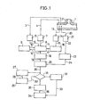
- a nozzle corner portion 2 of a header 1 of a superheater will be described.
- the header 1 has a thick wall, and is used in high temperature conditions close to 550°C. A difference in temperature between the inner and the outer surfaces of the header 1 occurs in accordance with changes in the fluid temperature and in the flowrate in the header 1 when the load on the boiler is changed such as when the boiler is started or stopped.
- the nozzle corner portion 2 being complicated in construction, has a correspondingly complicated distribution of generated stress and the stress is relatively high.
- the nozzle corner portion 2 is a portion where thermal stress is generated to a large degree.
- the pressure of the internal fluid at the time of steady-state operation can be as high as 255 Kg/cm 2 , at which the deterioration of the boiler due to the stress resulting from the internal pressure is highest.
- signals 3 and 4 relating to the metal temperature at the inner surface and the outer surface of the header 1 are generated. From those signals, a measured value 6 of the inner surface temperature of the metal is outputted by a metal inner surface temperature detector 5, a measured value 8 of the outer surface temperature of the metal is outputted by a metal outer surface temperature detector 7, respectively, and a calculated value 12 of the distribution of temperature in the direction of the metal thickness is calculated by a temperature distribution calculator 11 on the basis of the both measured values 6, 8 and a value 10 of the temperature distribution is outputted from a temperature distribution storing device 9.
- a signal 13 relating to the fluid temperature is generated from the interior of the header 1 and is detected by a fluid temperature detector 14 which outputs a measured value 15 of the fluid temperature.
- the rate of change of the fluid temperature is determined from the measured value 15 of the fluid temperature.
- the rate of change of the fluid temperature is compared with a range of a plurality of preset rates of change of the fluid temperature, and a preset value 17 of the calculation cycle is thereby preset, which corresponds to a respective one of the range of the plurality of rates of change in the fluid temperature.
- the calculated value 12 of the distribution of temperature in the direction of the metal thickness is stored in the temperature distribution storing device 9, and is fed to a thermal stress calculator 18 to calculate a value 19 of the thermal stress.
- a signal 20 relating to the pressure is detected from the header 1 by a pressure detector 21, and a calculated value 24 of the internal stress is produced by an internal stress calculator 23 from a measured value 22 of the steam pressure which is emitted by the pressure detector 21.
- a calculated value 24 of the internal pressure which is obtained from the measured value 22 of the steam pressure which is detected by the pressure detector 21 is added to the calculated value 19 of the thermal stress which is obtained from the calculated value 12 of the distribution of temperature in the direction of the metal thickness, thereby to calculate a calculated value 26 of the current stress.
- a value 28 of the amount of the life of the apparatus which has expired due to fatigue and creep is calculated on the basis of the calculated value 26 of the current stress.
- a stress limit value presetter 29 the calculated value 28 of the expired lifetime of the apparatus in operation is subtracted from a value of the life expectancy of the design which has been determined at the time of planning, taking into account every monitoring point and every operation mode, thereby to calculate the remaining life of the plant. Further, from the remaining life and remaining operation cycles, an allowable life consumption per future operation mode is determined, and the corresponding stress which would be generated, which is expected to bring about the life consumption, is preset as a preset value 30 of the stress limit of the header 1.
- the preset value 30 of the stress limit in the stress limit preset value setter 29 is adapted to be renewed with every desired start/stop cycle of the plant.
- the calculated value 26 of the current stress is compared with the preset value 30 of the stress limit in a comparator 31.
- a load hold signal 33 is generated in a load hold signal generator 32 and delivered to a boiler load controller 34.
- the nozzle corner portion 2 which is a stress concentrated portion in the header 1 in Fig. 1 is tested, and the generated stress and the life consumption are monitored.
- the measured value 15 of the fluid temperature is detected by the fluid temperature detector 14 in predetermined sample cycles.
- Fig. 3 is an enlarged sectional view taken along the line X-X in Fig. 2, showing a part of a cylindrical model for calculating the distribution of temperature.
- Thermal stress in a cylindrical portion is obtained from the distribution of temperature in the direction of the thickness of the cylindrical portion.
- the distribution of temperature is determined from the following equation (1) of heat conduction through the cylindrical portion.
- the cylindrical portion is divided into a plurality of portions N, which are cylinders concentric with one another, with radial points being disposed at regular intervals along the radius of the cylinder, and equation (1) is solved by a differential method.
- a differential equation is represented by equation (2), and equations corresponding to the respective radial points are obtainable as equations (3).
- the radial point 1 in Fig. 3 is represented by:
- the radial point 2 is represented by:
- the radial point 3 is represented by:
- the radial point n-1 is represented by: Here, where Ti,j: metal temperature (i: radial point parameter, j: time parameter),
- Equation (4) through (9) represent stresses generated in general portions of the cylinder.
- the stress generated in the stress concentrated portion such as the nozzle corner portion 2 is obtained by multiplying the stress generated in the general portion by a stress concentration factor.
- the stresses in the three directions of the current stress calculated value 26 generated in the nozzle corner portion 2 are obtainable through the equations (10) to (12).
- Krt radial thermal stress concentration factor
- the distribution of temperature in the direction of the thickness in the pressure-tight portion of the boiler in the prior art has heretofore been determined by measuring the distribution of temperature through a linear approximation by using the metal inner and outer surface measured values 6 and 8. In this case, even if the actual distribution of temperature in the direction of the metal thickness is represented by a curve, the measurement is made as if it is a straight line, whereby the measuring accuracy of the generated stress is reduced.
- the thermal stress measuring calculations can be performed in real time within the time of measuring the temperature, during which changes in temperature can be satisfactorily taken into account, so that changes in the distribution of temperature can be determined in a short period of time thereby enabling the generated stress to be measured with high accuracy.
- the boundary condition of the inner surface of the metal is determined by the coefficient of heat-transfer from the fluid in the interior of the tube to the metal.
- a measured value of the steam temperature is detected by a steam temperature detector
- a measured value of the steam flowrate is detected by a steam flowrate detector
- a measured value of the steam pressure is detected by the pressure detector.
- the coefficient of heat transfer from the steam to the metal is calculated in a heat-transfer coefficient calculator.
- the distribution of temperature in the metal may be obtained by the temperature distribution calculator.
- the equation (l) of the heat conduction of the cylinder is solved, with the following equation being taken as the boundary condition on the inner surface of the metal, and the distribution of temperature in the metal is thereby obtained.
- the calculation is made on the basis of the measured values of the inner and outer surface temperatures of the metal.
- the generated stress may be determined from the temperature, pressure, flowrate and the temperature of the outer surface of the metal.
- thermal stress monitoring point In the embodiment shown in Fig. 1, only one thermal stress monitoring point has been used. However, in practice, a plurality of such monitoring points as described above are provided, thus providing a method of operating the boiler, wherein all the requirements are satisfied.
- Fig. 4 shows an example of changes in the fluid temperature from the start of the boiler to steady-state operation.
- Fig. 4 shows that, at the time t l of a change in the load such as the start of the boiler, where fluctuations in the fluid temperature are large, a calculation cycle ⁇ t 1 is preset.
- a calculation cycle st 3 is preset.
- a calculation cycle ⁇ t 2 is preset.
- of the rate of change in the temperature is determined by use of the measured value 15 of the fluid temperature for detecting the fluid temperature at predetermined sample cycles.
- is preset.
- the calculation cycle for estimating the generated stress during the time period of monitoring the stress can be altered in accordance with the operating conditions of the boiler, whereby any useless calculation can be dispensed with, so that the load imposed upon the computer can be reduced. Furthermore, over the whole of the time period of monitoring the stress, the generated stress can be estimated in optimal calculation-cycles, so that the load imposed upon the computer can be reduced accordingly. For example, in Fig. 4, at the time of steady-state operation where fluctuations in the fluid temperature are small, the generated stress is estimated in the calculation cycle ⁇ t 2 or st 3 .
- the generated stress is estimated in the calculation cycle ⁇ t 1 , whereby, at the time of steady-state operation, the calculations are made once for every two cycles or three cycles of the calculation cycle ⁇ t 1 , so that the load imposed upon the computer can be decreased a factor of 2 or 3.
- the computer can be further utilized, due to the decrease of load, in performing calculations for other purposes of control or in adding a new function or functions. This results in economical use of the computer.
- the generated stress can be estimated with high accuracy when the boiler is under a full load, useless calculations are made at the time of steady-state operation, etc. of the boiler, resulting in excessive accuracy.
- the calculation cycles are short, while during steady-state operation, etc., when changes in the fluid temperature are small, the calculation cycles are long, so that over the total time period of stress monitoring, the generated stress can be estimated with uniform accuracy.
- the distribution of temperature in the direction of the metal thickness can be measured with high accuracy and the stress generated can be reliably measured. Furthermore, there is provided a calculation cycle setter for presetting the calculation cycles in accordance with the measured value of the fluid temperature, whereby, when the load changes and the fluid temperature fluctuates greatly, the calculation cycles are short, while, during steady-state operation when the fluctuations of the fluid temperature are small, the calculation cycles are long, so that the calculation cycles for estimating the generated stress can be altered in accordance with the operating conditions of the heating device. Moreover, the generated stress can be measured at a value close to the actual state.
Landscapes
- Engineering & Computer Science (AREA)
- Chemical & Material Sciences (AREA)
- Physics & Mathematics (AREA)
- Biochemistry (AREA)
- Thermal Sciences (AREA)
- Life Sciences & Earth Sciences (AREA)
- General Health & Medical Sciences (AREA)
- General Physics & Mathematics (AREA)
- Immunology (AREA)
- Pathology (AREA)
- Health & Medical Sciences (AREA)
- Combustion & Propulsion (AREA)
- Analytical Chemistry (AREA)
- Mechanical Engineering (AREA)
- General Engineering & Computer Science (AREA)
- Control Of Steam Boilers And Waste-Gas Boilers (AREA)
- Investigating Or Analyzing Materials Using Thermal Means (AREA)
- Investigating Strength Of Materials By Application Of Mechanical Stress (AREA)
- Measuring Fluid Pressure (AREA)
- Monitoring And Testing Of Nuclear Reactors (AREA)
- Control Of Turbines (AREA)
- Testing Resistance To Weather, Investigating Materials By Mechanical Methods (AREA)
Applications Claiming Priority (2)
| Application Number | Priority Date | Filing Date | Title |
|---|---|---|---|
| JP59081158A JPS60226603A (ja) | 1984-04-24 | 1984-04-24 | ボイラ熱応力予測装置 |
| JP81158/84 | 1984-04-24 |
Publications (4)
| Publication Number | Publication Date |
|---|---|
| EP0165675A2 true EP0165675A2 (fr) | 1985-12-27 |
| EP0165675A3 EP0165675A3 (en) | 1987-05-27 |
| EP0165675B1 EP0165675B1 (fr) | 1990-07-04 |
| EP0165675B2 EP0165675B2 (fr) | 1994-12-07 |
Family
ID=13738634
Family Applications (1)
| Application Number | Title | Priority Date | Filing Date |
|---|---|---|---|
| EP85302879A Expired - Lifetime EP0165675B2 (fr) | 1984-04-24 | 1985-04-24 | Appareil pour mesurer la contrainte thermique d'un tube sous pression |
Country Status (10)
| Country | Link |
|---|---|
| US (1) | US4792912A (fr) |
| EP (1) | EP0165675B2 (fr) |
| JP (1) | JPS60226603A (fr) |
| KR (1) | KR900005780B1 (fr) |
| AU (2) | AU590195B2 (fr) |
| DE (1) | DE3578532D1 (fr) |
| FI (1) | FI86109C (fr) |
| IN (1) | IN164821B (fr) |
| NO (1) | NO167107C (fr) |
| ZA (1) | ZA853058B (fr) |
Cited By (1)
| Publication number | Priority date | Publication date | Assignee | Title |
|---|---|---|---|---|
| EP2837777A1 (fr) * | 2013-08-16 | 2015-02-18 | ABB Technology AG | Procédé permettant de calculer la contrainte thermique dans un composant à paroi épaisse d'un système thermique |
Families Citing this family (9)
| Publication number | Priority date | Publication date | Assignee | Title |
|---|---|---|---|---|
| US4888953A (en) * | 1987-11-13 | 1989-12-26 | Babcock-Hitachi Kabushiki Kaisha | Apparatus for controlling boiler/turbine plant |
| US5157619A (en) * | 1988-10-31 | 1992-10-20 | Westinghouse Electric Corp. | Abnormal thermal loading effects monitoring system |
| US5050108A (en) * | 1989-11-30 | 1991-09-17 | Aptech Engineering, Inc. | Method for extending the useful life of boiler tubes |
| US5018356A (en) * | 1990-10-10 | 1991-05-28 | Westinghouse Electric Corp. | Temperature control of a steam turbine steam to minimize thermal stresses |
| JP3042066B2 (ja) * | 1991-09-05 | 2000-05-15 | 株式会社日立製作所 | プラントの制御システム |
| US5621654A (en) * | 1994-04-15 | 1997-04-15 | Long Island Lighting Company | System and method for economic dispatching of electrical power |
| JP2001082391A (ja) * | 1999-09-10 | 2001-03-27 | Ishikawajima Harima Heavy Ind Co Ltd | 流体機械の熱流体解析・熱応力解析方法 |
| KR20010103232A (ko) | 2000-05-08 | 2001-11-23 | 윤덕용 | 콘크리트 구조물의 온도응력 측정장치 및 방법 |
| DE10060706A1 (de) * | 2000-12-07 | 2002-06-13 | Flowtec Ag | Verfahren und eine Vorrichtung zur System- und/oder Prozeßüberwachung |
Family Cites Families (7)
| Publication number | Priority date | Publication date | Assignee | Title |
|---|---|---|---|---|
| GB2002543B (en) * | 1977-07-29 | 1982-02-17 | Hitachi Ltd | Rotor-stress preestimating turbine control system |
| US4173891A (en) * | 1978-01-12 | 1979-11-13 | Rockwell International Corporation | Method and apparatus for measuring gas flow |
| GB1601890A (en) * | 1978-05-31 | 1981-11-04 | Sira Institute | Apparatus and method for indicating stress in an object |
| SE427502B (sv) * | 1979-03-16 | 1983-04-11 | Memoteknik Ab | Vermegenomgangsmetare |
| JPS5651631A (en) * | 1979-10-02 | 1981-05-09 | Chiyou Lsi Gijutsu Kenkyu Kumiai | Measuring instrument for surface temperature distribution |
| JPS5717810A (en) * | 1980-07-07 | 1982-01-29 | Nippon Denso Co Ltd | Alarm method and device for vehicle |
| JPS5835304A (ja) * | 1981-08-28 | 1983-03-02 | 株式会社日立製作所 | 高圧給水加熱器のウオ−ミング方法及び同装置 |
-
1984
- 1984-04-24 JP JP59081158A patent/JPS60226603A/ja active Granted
-
1985
- 1985-04-20 IN IN302/MAS/85A patent/IN164821B/en unknown
- 1985-04-22 FI FI851582A patent/FI86109C/fi not_active IP Right Cessation
- 1985-04-23 NO NO851625A patent/NO167107C/no not_active IP Right Cessation
- 1985-04-24 EP EP85302879A patent/EP0165675B2/fr not_active Expired - Lifetime
- 1985-04-24 AU AU41692/85A patent/AU590195B2/en not_active Ceased
- 1985-04-24 ZA ZA853058A patent/ZA853058B/xx unknown
- 1985-04-24 KR KR1019850002764A patent/KR900005780B1/ko not_active Expired
- 1985-04-24 DE DE8585302879T patent/DE3578532D1/de not_active Expired - Lifetime
- 1985-04-24 US US06/726,645 patent/US4792912A/en not_active Expired - Lifetime
-
1990
- 1990-01-29 AU AU48785/90A patent/AU634998B2/en not_active Ceased
Cited By (1)
| Publication number | Priority date | Publication date | Assignee | Title |
|---|---|---|---|---|
| EP2837777A1 (fr) * | 2013-08-16 | 2015-02-18 | ABB Technology AG | Procédé permettant de calculer la contrainte thermique dans un composant à paroi épaisse d'un système thermique |
Also Published As
| Publication number | Publication date |
|---|---|
| NO167107C (no) | 1991-10-02 |
| AU4878590A (en) | 1990-05-17 |
| JPH0473041B2 (fr) | 1992-11-19 |
| AU590195B2 (en) | 1989-11-02 |
| ZA853058B (en) | 1985-12-24 |
| EP0165675B2 (fr) | 1994-12-07 |
| KR900005780B1 (ko) | 1990-08-11 |
| FI86109C (fi) | 1992-07-10 |
| KR850007484A (ko) | 1985-12-04 |
| JPS60226603A (ja) | 1985-11-11 |
| NO167107B (no) | 1991-06-24 |
| AU4169285A (en) | 1985-10-31 |
| FI851582L (fi) | 1985-10-25 |
| US4792912A (en) | 1988-12-20 |
| EP0165675B1 (fr) | 1990-07-04 |
| AU634998B2 (en) | 1993-03-11 |
| FI86109B (fi) | 1992-03-31 |
| FI851582A0 (fi) | 1985-04-22 |
| DE3578532D1 (de) | 1990-08-09 |
| EP0165675A3 (en) | 1987-05-27 |
| NO851625L (no) | 1985-10-25 |
| IN164821B (fr) | 1989-06-10 |
Similar Documents
| Publication | Publication Date | Title |
|---|---|---|
| US5992505A (en) | Fouling monitoring apparatus of heat exchanger and method thereof | |
| EP0030459B2 (fr) | Système de surveillance du fonctionnement d'un condenseur de vapeur | |
| US6678628B2 (en) | Apparatus and methods for monitoring and testing coolant recirculation systems | |
| Bankston | The transition from turbulent to laminar gas flow in a heated pipe | |
| EP0165675B1 (fr) | Appareil pour mesurer la contrainte thermique d'un tube sous pression | |
| Taler et al. | Analysis of thermal stresses in a boiler drum during start-up | |
| Sobota et al. | Measurement of the temperature of the fluid inside the tube based on the temperature measurement of the thermally insulated outer surface | |
| Taler et al. | Experimental verification of space marching methods for solving inverse heat conduction problems | |
| JP7623902B2 (ja) | 伝熱管の余寿命評価方法、及び伝熱管の余寿命評価装置 | |
| US3981444A (en) | Method for starting a steam-heated heat exchanger by regulating the pressure of the heating-steam | |
| CN116754101A (zh) | 一种高温固体壁面的温度测量修正方法 | |
| JP2003121290A (ja) | 漏洩検知装置 | |
| JPS59128429A (ja) | 耐圧部品の寿命監視法 | |
| Weber et al. | Convective transition boiling of water at medium pressure | |
| JPH0641805B2 (ja) | ボイラ装置 | |
| JPH0624645Y2 (ja) | ボイラの熱応力監視装置 | |
| JP2851868B2 (ja) | 運転支援装置 | |
| JPH0392796A (ja) | 蒸気発生器の運転監視方法 | |
| JPS57166541A (en) | Method and device estimating life of fluid receptacle at high temperature | |
| US20170003178A1 (en) | Method and apparatus for determining the skin temperatures of heat-exchange tubes in a fired tubular gas heater | |
| SU1489339A1 (ru) | Способ определения интенсивности орошения е парогенерирующих каналах с генераторами возмущений | |
| Garrett | Heat-transfer coefficients for film condensation of steam on an inclined cylinder | |
| JPS6031029A (ja) | 蓄熱量測定方法 | |
| JPS6011002A (ja) | ボイラ負荷制御装置 | |
| WEBER et al. | Berlin, Federal Republic of Germany |
Legal Events
| Date | Code | Title | Description |
|---|---|---|---|
| PUAI | Public reference made under article 153(3) epc to a published international application that has entered the european phase |
Free format text: ORIGINAL CODE: 0009012 |
|
| AK | Designated contracting states |
Designated state(s): DE GB IT NL |
|
| PUAL | Search report despatched |
Free format text: ORIGINAL CODE: 0009013 |
|
| AK | Designated contracting states |
Kind code of ref document: A3 Designated state(s): DE GB IT NL |
|
| 17P | Request for examination filed |
Effective date: 19870905 |
|
| 17Q | First examination report despatched |
Effective date: 19890712 |
|
| GRAA | (expected) grant |
Free format text: ORIGINAL CODE: 0009210 |
|
| AK | Designated contracting states |
Kind code of ref document: B1 Designated state(s): DE GB IT NL |
|
| ITF | It: translation for a ep patent filed | ||
| REF | Corresponds to: |
Ref document number: 3578532 Country of ref document: DE Date of ref document: 19900809 |
|
| PLBI | Opposition filed |
Free format text: ORIGINAL CODE: 0009260 |
|
| 26 | Opposition filed |
Opponent name: SIEMENS AKTIENGESELLSCHAFT, BERLIN UND MUENCHEN Effective date: 19901214 |
|
| NLR1 | Nl: opposition has been filed with the epo |
Opponent name: SIEMENS AG |
|
| ITTA | It: last paid annual fee | ||
| PUAH | Patent maintained in amended form |
Free format text: ORIGINAL CODE: 0009272 |
|
| STAA | Information on the status of an ep patent application or granted ep patent |
Free format text: STATUS: PATENT MAINTAINED AS AMENDED |
|
| 27A | Patent maintained in amended form |
Effective date: 19941207 |
|
| AK | Designated contracting states |
Kind code of ref document: B2 Designated state(s): DE GB IT NL |
|
| ITF | It: translation for a ep patent filed | ||
| NLR2 | Nl: decision of opposition | ||
| NLR3 | Nl: receipt of modified translations in the netherlands language after an opposition procedure | ||
| REG | Reference to a national code |
Ref country code: GB Ref legal event code: IF02 |
|
| PGFP | Annual fee paid to national office [announced via postgrant information from national office to epo] |
Ref country code: GB Payment date: 20030416 Year of fee payment: 19 |
|
| PGFP | Annual fee paid to national office [announced via postgrant information from national office to epo] |
Ref country code: NL Payment date: 20030429 Year of fee payment: 19 |
|
| PGFP | Annual fee paid to national office [announced via postgrant information from national office to epo] |
Ref country code: DE Payment date: 20030515 Year of fee payment: 19 |
|
| PG25 | Lapsed in a contracting state [announced via postgrant information from national office to epo] |
Ref country code: GB Free format text: LAPSE BECAUSE OF NON-PAYMENT OF DUE FEES Effective date: 20040424 |
|
| PG25 | Lapsed in a contracting state [announced via postgrant information from national office to epo] |
Ref country code: NL Free format text: LAPSE BECAUSE OF NON-PAYMENT OF DUE FEES Effective date: 20041101 |
|
| PG25 | Lapsed in a contracting state [announced via postgrant information from national office to epo] |
Ref country code: DE Free format text: LAPSE BECAUSE OF NON-PAYMENT OF DUE FEES Effective date: 20041103 |
|
| GBPC | Gb: european patent ceased through non-payment of renewal fee |
Effective date: 20040424 |
|
| NLV4 | Nl: lapsed or anulled due to non-payment of the annual fee |
Effective date: 20041101 |