EP0165687A1 - Zusammenstellung eines Schneidewerkzeuges - Google Patents
Zusammenstellung eines Schneidewerkzeuges Download PDFInfo
- Publication number
- EP0165687A1 EP0165687A1 EP85303098A EP85303098A EP0165687A1 EP 0165687 A1 EP0165687 A1 EP 0165687A1 EP 85303098 A EP85303098 A EP 85303098A EP 85303098 A EP85303098 A EP 85303098A EP 0165687 A1 EP0165687 A1 EP 0165687A1
- Authority
- EP
- European Patent Office
- Prior art keywords
- housing
- drill bit
- nozzle
- cutter assembly
- cutter
- Prior art date
- Legal status (The legal status is an assumption and is not a legal conclusion. Google has not performed a legal analysis and makes no representation as to the accuracy of the status listed.)
- Withdrawn
Links
Images
Classifications
-
- E—FIXED CONSTRUCTIONS
- E21—EARTH OR ROCK DRILLING; MINING
- E21B—EARTH OR ROCK DRILLING; OBTAINING OIL, GAS, WATER, SOLUBLE OR MELTABLE MATERIALS OR A SLURRY OF MINERALS FROM WELLS
- E21B10/00—Drill bits
- E21B10/62—Drill bits characterised by parts, e.g. cutting elements, which are detachable or adjustable
-
- E—FIXED CONSTRUCTIONS
- E21—EARTH OR ROCK DRILLING; MINING
- E21B—EARTH OR ROCK DRILLING; OBTAINING OIL, GAS, WATER, SOLUBLE OR MELTABLE MATERIALS OR A SLURRY OF MINERALS FROM WELLS
- E21B10/00—Drill bits
- E21B10/46—Drill bits characterised by wear resisting parts, e.g. diamond inserts
- E21B10/58—Chisel-type inserts
-
- E—FIXED CONSTRUCTIONS
- E21—EARTH OR ROCK DRILLING; MINING
- E21B—EARTH OR ROCK DRILLING; OBTAINING OIL, GAS, WATER, SOLUBLE OR MELTABLE MATERIALS OR A SLURRY OF MINERALS FROM WELLS
- E21B10/00—Drill bits
- E21B10/60—Drill bits characterised by conduits or nozzles for drilling fluids
Definitions
- the instant invention broadly relates to drilling in general and more particularly to cutting bits for effecting drilling.
- rock The drilling of boreholes in rock, ore, coal and concrete (hereinafter "rock"), is a task performed during the course of operations common to the mining, construction and petroleum industries.
- Typical uses for boreholes include placement of explosives, placement of rock support pins and tapping deposits of natural gas and petroleum.
- Typical drilling machines produce boreholes in rock by pushing an elongated hollow tool stem (drill rod, drill steel, drill pipe) having a workface with hardened cutters (drill bit) against the rock while applying rotating and/or impacting forces to the drill bit.
- the cutter edges on the drill bit break particles of rock and scrape them away, enabling the drill bit to advance progressively into the rock, creating a borehole.
- the rock particles are normally flushed away from the vorkface and out of the borehole around the advancing drill rod by means of a fluid (usually water) pumped through the drill rod and emitted near the workface through fluid passages in the drill bit.
- the velocity of the fluid exiting through the drill bit passages is normally less than 8oo feet per second (244m/sec) and the passages normally have a diameter greater than .100 inch (2.54mm).
- Rapid dulling of the drill bit cutter edges occurs because of the abrasiveness of the rock and the severe mechanical stress transmitted through the cutter edges into the rock. Dulling of the cutter edges substantially reduces the rate at which the borehole is advanced.
- many drill rods use detachable drill bits that can be easily removed from the drill rod. This makes it practical for the drilling machine operator to have a plurality of drill bits available at the work site, where they can be quickly replaced when dull and resharpended at the convenience of the operator without delaying the drilling operation.
- a typical drill bit assembly consists of a short body with means of attaching it to the drill rod.
- the assembly further includes fluid passages which are connected to fluid passage of the drill rod.
- the cutters on the workface are usually constructed of hardened steel, tungsten carbide, diamond or other similarly wear resistant materials. When wear limits are reached, the entire drill bit assembly is normally scrapped.
- differential pressure across the nozzles in the drill bit will range from about 5,000 to 60,000 lba./in 2 (34.5 MPa -413.7 MPa) or higher depending on the hardness and type of rock encountered. Jet velocities must normally exceed about 800 feet per second and the fluid passage orifice (nozzle) diameters will normally be less than about .060 inches (1.5mm), with nozzles as about small as about .003 inch (.07mm) diameter sometimes used.
- the nozzle housings and cutter assemblies are attached together in such a way that a dull cutter assembly cannot be removed without loosening or removing the nozzle housing.
- accidental contamination of fluid passages causing plugging of nozzle orifices is one of the most common problems with fluid jet apparatus.
- the disclosed concept allows the cutter assembly to be quickly removed without loosening any fluid passage connection or allowing the possibility of dirt entering the fluid passages.
- Some of the prior attempts use small nozzle housings that must be located at the center of the cutter assembly. As borehole diameter increases, the fluid cutting jets must travel progressively longer distances to reach the outer portions of the borehole workface. This greatly reduces cutting efficiency, due to the tendency of fluid jets to decay within a short distance of the nozzle orifice when emitted into the slurry environment present at the workface of a borehole. Additionally, the geometry of the nozzle housings limit the quantity of cutting jets that can fit into the housing. These factors make the previous attempts very inefficient for larger diameter boreholes. The disclosed concept uses multiple nozzle orifice located at a uniformly close proximity to the borehole workface all across the workface diameter, enabling much better fluid jet cutting efficiency in larger diameter boreholes.
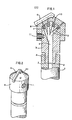
- a drill bit with multiple fluid jet cutting nozzles designed so that the drill bit workface including the cutters is a separate piece from the drill bit body that houses the fluid jet nozzle orifice mounts.
- the separate workface piece will be referred to as a "cutter assembly” and the drill bit body with fluid passages and orifice mounts will be referred to as a "nozzle housing”.
- the cutter assembly protects the nozzle housing from rapid wear and it can be easily removed from the nozzle housing without disturbing or removing any of the nozzle orifice mounts.
- the cutter assembly is tightly secured to the nozzle housing by means of a threaded member extending there-between.
- the cutters are resharpenable if desired and the cutter assembly can be scrapped after wear limits are reached, without the need to remove or scrap the nozzle housing.
- the servicable life of the nozzle housing is greatly extended, thereby substantially reducing the cost of drilling boreholes with fluid jet cutting assist.
- the drill rod 1 is attached to a suitable device able to rotate the drill rod 1 or rotate and impact the drill rod 1 while thrusting axially against the drill rod 1 in the intended direction for advancing the borehole.
- Fluid passage 2 in the drill rod 1 is connected to a fluid pumping source (not shown) via a rotatable fluid supply swivel connection (not shown) that enables fluid from the pump to enter the passage 2 in the rotating drill rod 1.
- Nozzle housing 3 includes drill rod attachment means 4 with fluid passage sealing connection 5 enabling nozzle housing fluid passage 6 to connect with the drill rod fluid passage 2 without any fluid leakage.
- the nozzle housing fluid passage 6 has a plurality of branches 12 supplying fluid to the nozzle orifice mounts 7 which are located near the surface of the nozzle housing 3 that is nearest the borehole workface.
- the cutter assembly 8 includes one or more hardened cutter edges 9, and a plurality of small passages 10 through which the fluid jets are emitted after exiting the nozzle orifices 7. Each passage 10 is placed so as to be concentrically aligned with a corresponding nozzle orifice 7.
- the cutter assembly 8 is attached to and aligned with the nozzle housing 3 by securing means 11, which is designed to withstand torsional and thrusting forces that could cause mis-alignment of the passages 10 with the nozzle orifices 7 or cause accidental detachment of the cutter assembly 8.
- the securing means 11, in the illustrated embodiment, is a recessed set screw traversing the cutter assembly 8 and threadedly extending into the nozzle housing 3.
- the hardened cutter edges 9 extend laterally beyond the sides of cutter assembly 8 a sufficient distance to allow clearance for rock chips and slurry to flow away from the borehole workface.
- the diameter of the fluid passage 10 may range from about 2 times the diameter of the orifice 7 to a maximum of about .100 inch (2.5mm).
- the disclosed invention may be applied to borehole drilling in the mining construction and petroleum industries.
- the bit may be used with high pressure industrial cleaning, scarification of concrete, cutting deep wide slots in rock and concrete, and as a cutter face for directional drills employed by utilities and coal industries.
Landscapes
- Engineering & Computer Science (AREA)
- Geology (AREA)
- Life Sciences & Earth Sciences (AREA)
- Mining & Mineral Resources (AREA)
- Physics & Mathematics (AREA)
- Environmental & Geological Engineering (AREA)
- Fluid Mechanics (AREA)
- Mechanical Engineering (AREA)
- General Life Sciences & Earth Sciences (AREA)
- Geochemistry & Mineralogy (AREA)
- Earth Drilling (AREA)
- External Artificial Organs (AREA)
- Materials For Medical Uses (AREA)
- Seal Device For Vehicle (AREA)
Applications Claiming Priority (2)
| Application Number | Priority Date | Filing Date | Title |
|---|---|---|---|
| US607017 | 1984-05-03 | ||
| US06/607,017 US4540056A (en) | 1984-05-03 | 1984-05-03 | Cutter assembly |
Publications (1)
| Publication Number | Publication Date |
|---|---|
| EP0165687A1 true EP0165687A1 (de) | 1985-12-27 |
Family
ID=24430446
Family Applications (1)
| Application Number | Title | Priority Date | Filing Date |
|---|---|---|---|
| EP85303098A Withdrawn EP0165687A1 (de) | 1984-05-03 | 1985-05-01 | Zusammenstellung eines Schneidewerkzeuges |
Country Status (11)
| Country | Link |
|---|---|
| US (1) | US4540056A (de) |
| EP (1) | EP0165687A1 (de) |
| JP (1) | JPS6157788A (de) |
| KR (1) | KR850008107A (de) |
| AU (1) | AU567808B2 (de) |
| CA (1) | CA1244001A (de) |
| FI (1) | FI851403A7 (de) |
| NO (1) | NO851740L (de) |
| ZA (1) | ZA85730B (de) |
| ZM (1) | ZM985A1 (de) |
| ZW (1) | ZW3685A1 (de) |
Cited By (4)
| Publication number | Priority date | Publication date | Assignee | Title |
|---|---|---|---|---|
| DE8712275U1 (de) * | 1987-09-10 | 1987-12-10 | Fa. Michael Hartfuss, 6604 Güdingen | Drehbohrwerkzeug |
| DE9002368U1 (de) * | 1990-03-01 | 1991-01-03 | Bilfinger + Berger Bauaktiengesellschaft, 6800 Mannheim | Vortriebseinheit |
| EP0430590A1 (de) * | 1989-11-25 | 1991-06-05 | Camco Drilling Group Limited | Verbesserungen an Drehbohrmeisseln |
| RU2165020C1 (ru) * | 1999-12-15 | 2001-04-10 | Тульский государственный университет | Гидромониторная насадка |
Families Citing this family (20)
| Publication number | Priority date | Publication date | Assignee | Title |
|---|---|---|---|---|
| US5176472A (en) * | 1983-02-08 | 1993-01-05 | Kinder William D | Foundation shoring method and means |
| US5018905A (en) * | 1985-12-11 | 1991-05-28 | Kinder William D | Foundation shoring method and means |
| FR2566832B1 (fr) * | 1984-06-27 | 1986-11-14 | Inst Francais Du Petrole | Methode et perfectionnement aux outils de forage permettant une grande efficacite du nettoyage du front de taille |
| FR2566833B1 (fr) * | 1984-06-27 | 1986-11-14 | Inst Francais Du Petrole | Methode et perfectionnement aux outils de forage comportant des passages d'eau permettant une grande efficacite du nettoyage du front de taille |
| US5115873A (en) * | 1991-01-24 | 1992-05-26 | Baker Hughes Incorporated | Method and appartus for directing drilling fluid to the cutting edge of a cutter |
| US5634515A (en) * | 1995-12-28 | 1997-06-03 | Lambert; Kenneth W. | Geothermal heat-pump system and installation of same |
| US5732784A (en) * | 1996-07-25 | 1998-03-31 | Nelson; Jack R. | Cutting means for drag drill bits |
| US6953303B1 (en) * | 2002-12-31 | 2005-10-11 | Waterwerks Inc. | Substrate removal apparatus |
| DE102006000081A1 (de) * | 2006-02-20 | 2007-08-23 | Hilti Ag | Gesteinsbohrkopf |
| US8100201B2 (en) * | 2008-07-25 | 2012-01-24 | Bluefire Equipment Corporation | Rotary drill bit |
| US20100276206A1 (en) * | 2008-07-25 | 2010-11-04 | Anatoli Borissov | Rotary Drill Bit |
| US20120111641A1 (en) * | 2010-09-13 | 2012-05-10 | Pak Yiu Ho | Detachable drill bit |
| US8904912B2 (en) | 2012-08-16 | 2014-12-09 | Omax Corporation | Control valves for waterjet systems and related devices, systems, and methods |
| US11554461B1 (en) | 2018-02-13 | 2023-01-17 | Omax Corporation | Articulating apparatus of a waterjet system and related technology |
| USD863383S1 (en) * | 2018-04-17 | 2019-10-15 | Dirt Duck, Llc | Fluid drilling head |
| WO2021127253A1 (en) | 2019-12-18 | 2021-06-24 | Hypertherm, Inc. | Liquid jet cutting head sensor systems and methods |
| EP4127527A1 (de) | 2020-03-24 | 2023-02-08 | Hypertherm, Inc. | Hochdruckdichtung für ein flüssigkeitsstrahlschneidsystem |
| KR20230005840A (ko) | 2020-03-30 | 2023-01-10 | 하이퍼썸, 인크. | 다기능 접속 종방향 단부들을 갖는 액체 제트 펌프를 위한 실린더 |
| CN116378573B (zh) * | 2023-04-07 | 2026-03-13 | 东北石油大学 | 一种自吸式粒子冲击钻头 |
| US11988046B1 (en) | 2023-10-22 | 2024-05-21 | Cool Edge Bits | Hydrojets rotary drill bit |
Citations (5)
| Publication number | Priority date | Publication date | Assignee | Title |
|---|---|---|---|---|
| US1388490A (en) * | 1920-09-18 | 1921-08-23 | John R Suman | Rotary earth-boring drill |
| US2773672A (en) * | 1952-09-17 | 1956-12-11 | Ellis C Holmes | Drilling bit |
| US3382940A (en) * | 1965-10-21 | 1968-05-14 | Frank E. Stebley | Percussion drill bit |
| US4083415A (en) * | 1975-12-18 | 1978-04-11 | Kennametal Inc. | Mining bit with replaceable work engaging member |
| US4413689A (en) * | 1982-06-01 | 1983-11-08 | Ingersoll-Rand Co. | Plural-part earth bit, and an improved bit head therefor |
Family Cites Families (13)
| Publication number | Priority date | Publication date | Assignee | Title |
|---|---|---|---|---|
| US554968A (en) * | 1896-02-18 | Half to joseph m | ||
| US1774522A (en) * | 1927-07-27 | 1930-09-02 | John T Phipps | Earth-boring drill |
| US2884227A (en) * | 1956-06-27 | 1959-04-28 | Sandvikens Jernverks Ab | Percussion drill bit for large holes |
| US3112803A (en) * | 1962-01-02 | 1963-12-03 | Jersey Prod Res Co | Diamond drill bit |
| US3688852A (en) * | 1970-08-24 | 1972-09-05 | Gulf Research Development Co | Spiral coil nozzle holder |
| US3871488A (en) * | 1974-02-13 | 1975-03-18 | Daniel R Sabre | Rock drilling |
| US3952819A (en) * | 1975-03-10 | 1976-04-27 | A & W Deep-Well Drilling, Inc. | Fatigue resistant anvil bit for percussion rock drill |
| US4190125A (en) * | 1977-11-09 | 1980-02-26 | Fansteel Inc. | Drill bit and steel combination for improved fluid flow |
| NO810302L (no) * | 1980-02-02 | 1981-08-03 | Drilling & Service Uk Ltd | Borkrone og anvendelse av samme. |
| US4341273A (en) * | 1980-07-04 | 1982-07-27 | Shell Oil Company | Rotary bit with jet nozzles |
| DE3039632C2 (de) * | 1980-10-21 | 1982-12-16 | Christensen, Inc., 84115 Salt Lake City, Utah | Drehborhmeißel für Tiefbohrungen |
| US4406336A (en) * | 1981-02-09 | 1983-09-27 | Olsen John K | Drilling bit |
| DE3330025A1 (de) * | 1982-08-30 | 1984-03-01 | Ingersoll-Rand Co., 07675 Woodcliff Lake, N.J. | Zweistueckiger bohrer |
-
1984
- 1984-05-03 US US06/607,017 patent/US4540056A/en not_active Expired - Lifetime
-
1985
- 1985-01-30 ZA ZA85730A patent/ZA85730B/xx unknown
- 1985-02-04 KR KR1019850000684A patent/KR850008107A/ko not_active Ceased
- 1985-02-06 CA CA000473648A patent/CA1244001A/en not_active Expired
- 1985-03-06 ZW ZW36/85A patent/ZW3685A1/xx unknown
- 1985-03-13 ZM ZM9/85A patent/ZM985A1/xx unknown
- 1985-04-09 FI FI851403A patent/FI851403A7/fi not_active Application Discontinuation
- 1985-05-01 EP EP85303098A patent/EP0165687A1/de not_active Withdrawn
- 1985-05-01 JP JP60094539A patent/JPS6157788A/ja active Pending
- 1985-05-02 NO NO851740A patent/NO851740L/no unknown
- 1985-05-02 AU AU41910/85A patent/AU567808B2/en not_active Ceased
Patent Citations (5)
| Publication number | Priority date | Publication date | Assignee | Title |
|---|---|---|---|---|
| US1388490A (en) * | 1920-09-18 | 1921-08-23 | John R Suman | Rotary earth-boring drill |
| US2773672A (en) * | 1952-09-17 | 1956-12-11 | Ellis C Holmes | Drilling bit |
| US3382940A (en) * | 1965-10-21 | 1968-05-14 | Frank E. Stebley | Percussion drill bit |
| US4083415A (en) * | 1975-12-18 | 1978-04-11 | Kennametal Inc. | Mining bit with replaceable work engaging member |
| US4413689A (en) * | 1982-06-01 | 1983-11-08 | Ingersoll-Rand Co. | Plural-part earth bit, and an improved bit head therefor |
Cited By (5)
| Publication number | Priority date | Publication date | Assignee | Title |
|---|---|---|---|---|
| DE8712275U1 (de) * | 1987-09-10 | 1987-12-10 | Fa. Michael Hartfuss, 6604 Güdingen | Drehbohrwerkzeug |
| EP0430590A1 (de) * | 1989-11-25 | 1991-06-05 | Camco Drilling Group Limited | Verbesserungen an Drehbohrmeisseln |
| US5119892A (en) * | 1989-11-25 | 1992-06-09 | Reed Tool Company Limited | Notary drill bits |
| DE9002368U1 (de) * | 1990-03-01 | 1991-01-03 | Bilfinger + Berger Bauaktiengesellschaft, 6800 Mannheim | Vortriebseinheit |
| RU2165020C1 (ru) * | 1999-12-15 | 2001-04-10 | Тульский государственный университет | Гидромониторная насадка |
Also Published As
| Publication number | Publication date |
|---|---|
| US4540056A (en) | 1985-09-10 |
| ZA85730B (en) | 1985-09-25 |
| FI851403A0 (fi) | 1985-04-09 |
| KR850008107A (ko) | 1985-12-13 |
| FI851403L (fi) | 1985-11-04 |
| AU4191085A (en) | 1985-11-07 |
| NO851740L (no) | 1985-11-04 |
| AU567808B2 (en) | 1987-12-03 |
| CA1244001A (en) | 1988-11-01 |
| JPS6157788A (ja) | 1986-03-24 |
| ZW3685A1 (en) | 1985-06-26 |
| ZM985A1 (en) | 1985-08-22 |
| FI851403A7 (fi) | 1985-11-04 |
Similar Documents
| Publication | Publication Date | Title |
|---|---|---|
| US4540056A (en) | Cutter assembly | |
| US4535853A (en) | Drill bit for jet assisted rotary drilling | |
| US4991667A (en) | Hydraulic drilling apparatus and method | |
| EP0198060B1 (de) | Methode und gerät zum kombinierten jet- und mechanischbohren | |
| US6450269B1 (en) | Method and bit for directional horizontal boring | |
| US4106577A (en) | Hydromechanical drilling device | |
| US4739845A (en) | Nozzle for rotary bit | |
| US6209660B1 (en) | Drill bit shear relief for horizontal directional drilling of rock formations | |
| US4381825A (en) | Drill bit nozzle | |
| US4533005A (en) | Adjustable nozzle | |
| US7017684B2 (en) | Jet cutting device with deflector | |
| AU2001288875A1 (en) | Method and bit for directional horizontal boring | |
| US9109412B2 (en) | Rotational drill bits and drilling apparatuses including the same | |
| EP0626500A2 (de) | Mehrfachschneiden-Richtbohrkopf | |
| US5799740A (en) | Directional boring head with blade assembly | |
| GB2367312A (en) | Positively raked cutting element for a rotary/drag bit having a scoop like formation for directing cuttings | |
| US6926100B1 (en) | Hole reaming apparatus and method | |
| US5469926A (en) | Directional boring drill bit blade | |
| US4359115A (en) | Novel rotary drill bits and drilling process | |
| US4632196A (en) | Drill bit with shrouded cutter | |
| USRE37975E1 (en) | Directional boring head with blade assembly | |
| GB2120156A (en) | Rotary-percussive drill assembly | |
| RU1821553C (ru) | Устройство дл ударного бурени скважин | |
| US20220349259A1 (en) | Drill assembly and method of using same | |
| CA1160213A (en) | Drill bit nozzle |
Legal Events
| Date | Code | Title | Description |
|---|---|---|---|
| PUAI | Public reference made under article 153(3) epc to a published international application that has entered the european phase |
Free format text: ORIGINAL CODE: 0009012 |
|
| AK | Designated contracting states |
Designated state(s): AT BE CH DE FR GB IT LI LU NL SE |
|
| 17P | Request for examination filed |
Effective date: 19860605 |
|
| 17Q | First examination report despatched |
Effective date: 19870619 |
|
| STAA | Information on the status of an ep patent application or granted ep patent |
Free format text: STATUS: THE APPLICATION HAS BEEN WITHDRAWN |
|
| 18W | Application withdrawn |
Withdrawal date: 19890114 |
|
| RIN1 | Information on inventor provided before grant (corrected) |
Inventor name: O'HANLON, THOMAS A. |