EP0165691A1 - Pièces de liaison de tuyaux sans emboîtement - Google Patents
Pièces de liaison de tuyaux sans emboîtement Download PDFInfo
- Publication number
- EP0165691A1 EP0165691A1 EP85303157A EP85303157A EP0165691A1 EP 0165691 A1 EP0165691 A1 EP 0165691A1 EP 85303157 A EP85303157 A EP 85303157A EP 85303157 A EP85303157 A EP 85303157A EP 0165691 A1 EP0165691 A1 EP 0165691A1
- Authority
- EP
- European Patent Office
- Prior art keywords
- gasket
- pipes
- bridge element
- socket
- pipe joint
- Prior art date
- Legal status (The legal status is an assumption and is not a legal conclusion. Google has not performed a legal analysis and makes no representation as to the accuracy of the status listed.)
- Ceased
Links
- 239000002184 metal Substances 0.000 claims abstract description 18
- 229910052751 metal Inorganic materials 0.000 claims abstract description 18
- 230000015572 biosynthetic process Effects 0.000 claims abstract description 12
- 238000005755 formation reaction Methods 0.000 claims abstract description 12
- 239000004020 conductor Substances 0.000 claims abstract description 11
- 238000007789 sealing Methods 0.000 claims abstract description 11
- 239000012777 electrically insulating material Substances 0.000 claims abstract description 4
- 230000000717 retained effect Effects 0.000 claims abstract description 3
- 239000000463 material Substances 0.000 claims description 6
- 230000001419 dependent effect Effects 0.000 claims 1
- 239000002689 soil Substances 0.000 abstract description 4
- 210000005069 ears Anatomy 0.000 description 5
- 229910001220 stainless steel Inorganic materials 0.000 description 5
- 239000010935 stainless steel Substances 0.000 description 5
- 230000004323 axial length Effects 0.000 description 2
- 238000005452 bending Methods 0.000 description 2
- 239000011248 coating agent Substances 0.000 description 2
- 238000000576 coating method Methods 0.000 description 2
- 230000007797 corrosion Effects 0.000 description 2
- 238000005260 corrosion Methods 0.000 description 2
- 239000011810 insulating material Substances 0.000 description 2
- 229920003051 synthetic elastomer Polymers 0.000 description 2
- 239000005061 synthetic rubber Substances 0.000 description 2
- 229910001018 Cast iron Inorganic materials 0.000 description 1
- 229910000831 Steel Inorganic materials 0.000 description 1
- 230000000295 complement effect Effects 0.000 description 1
- 210000000883 ear external Anatomy 0.000 description 1
- 230000000694 effects Effects 0.000 description 1
- 229920001971 elastomer Polymers 0.000 description 1
- 238000012986 modification Methods 0.000 description 1
- 230000004048 modification Effects 0.000 description 1
- 238000000465 moulding Methods 0.000 description 1
- 230000000149 penetrating effect Effects 0.000 description 1
- 239000004033 plastic Substances 0.000 description 1
- 229920003023 plastic Polymers 0.000 description 1
- 239000011253 protective coating Substances 0.000 description 1
- 239000005060 rubber Substances 0.000 description 1
- 239000010959 steel Substances 0.000 description 1
- 239000002699 waste material Substances 0.000 description 1
- XLYOFNOQVPJJNP-UHFFFAOYSA-N water Substances O XLYOFNOQVPJJNP-UHFFFAOYSA-N 0.000 description 1
Images

Classifications
-
- F—MECHANICAL ENGINEERING; LIGHTING; HEATING; WEAPONS; BLASTING
- F16—ENGINEERING ELEMENTS AND UNITS; GENERAL MEASURES FOR PRODUCING AND MAINTAINING EFFECTIVE FUNCTIONING OF MACHINES OR INSTALLATIONS; THERMAL INSULATION IN GENERAL
- F16L—PIPES; JOINTS OR FITTINGS FOR PIPES; SUPPORTS FOR PIPES, CABLES OR PROTECTIVE TUBING; MEANS FOR THERMAL INSULATION IN GENERAL
- F16L21/00—Joints with sleeve or socket
- F16L21/002—Sleeves or nipples for pipes of the same diameter; Reduction pieces
- F16L21/005—Sleeves or nipples for pipes of the same diameter; Reduction pieces made of elastic material, e.g. partly or completely surrounded by clamping devices
-
- F—MECHANICAL ENGINEERING; LIGHTING; HEATING; WEAPONS; BLASTING
- F16—ENGINEERING ELEMENTS AND UNITS; GENERAL MEASURES FOR PRODUCING AND MAINTAINING EFFECTIVE FUNCTIONING OF MACHINES OR INSTALLATIONS; THERMAL INSULATION IN GENERAL
- F16L—PIPES; JOINTS OR FITTINGS FOR PIPES; SUPPORTS FOR PIPES, CABLES OR PROTECTIVE TUBING; MEANS FOR THERMAL INSULATION IN GENERAL
- F16L25/00—Construction or details of pipe joints not provided for in, or of interest apart from, groups F16L13/00 - F16L23/00
- F16L25/01—Construction or details of pipe joints not provided for in, or of interest apart from, groups F16L13/00 - F16L23/00 specially adapted for realising electrical conduction between the two pipe ends of the joint or between parts thereof
-
- H—ELECTRICITY
- H01—ELECTRIC ELEMENTS
- H01R—ELECTRICALLY-CONDUCTIVE CONNECTIONS; STRUCTURAL ASSOCIATIONS OF A PLURALITY OF MUTUALLY-INSULATED ELECTRICAL CONNECTING ELEMENTS; COUPLING DEVICES; CURRENT COLLECTORS
- H01R4/00—Electrically-conductive connections between two or more conductive members in direct contact, i.e. touching one another; Means for effecting or maintaining such contact; Electrically-conductive connections having two or more spaced connecting locations for conductors and using contact members penetrating insulation
- H01R4/58—Electrically-conductive connections between two or more conductive members in direct contact, i.e. touching one another; Means for effecting or maintaining such contact; Electrically-conductive connections having two or more spaced connecting locations for conductors and using contact members penetrating insulation characterised by the form or material of the contacting members
- H01R4/64—Connections between or with conductive parts having primarily a non-electric function, e.g. frame, casing, rail
- H01R4/643—Connections between or with conductive parts having primarily a non-electric function, e.g. frame, casing, rail for rigid cylindrical bodies
-
- H—ELECTRICITY
- H01—ELECTRIC ELEMENTS
- H01R—ELECTRICALLY-CONDUCTIVE CONNECTIONS; STRUCTURAL ASSOCIATIONS OF A PLURALITY OF MUTUALLY-INSULATED ELECTRICAL CONNECTING ELEMENTS; COUPLING DEVICES; CURRENT COLLECTORS
- H01R4/00—Electrically-conductive connections between two or more conductive members in direct contact, i.e. touching one another; Means for effecting or maintaining such contact; Electrically-conductive connections having two or more spaced connecting locations for conductors and using contact members penetrating insulation
- H01R4/70—Insulation of connections
-
- H—ELECTRICITY
- H01—ELECTRIC ELEMENTS
- H01R—ELECTRICALLY-CONDUCTIVE CONNECTIONS; STRUCTURAL ASSOCIATIONS OF A PLURALITY OF MUTUALLY-INSULATED ELECTRICAL CONNECTING ELEMENTS; COUPLING DEVICES; CURRENT COLLECTORS
- H01R4/00—Electrically-conductive connections between two or more conductive members in direct contact, i.e. touching one another; Means for effecting or maintaining such contact; Electrically-conductive connections having two or more spaced connecting locations for conductors and using contact members penetrating insulation
- H01R4/28—Clamped connections, spring connections
- H01R4/38—Clamped connections, spring connections utilising a clamping member acted on by screw or nut
- H01R4/44—Clamping areas on both sides of screw
Definitions
- This invention relates to socket-less pipe joints which connect pipes in butting end to end relationship, and more particularly to such joints as applied to metal pipes.
- the joints may be used, for example, in drain, soil, waste and vent pipe, and water supply pipe, runs.
- pipe is intended to include not only pipes, tubes and the like but also hollow fittings, such as bends, elbows and T junctions, which are incorporated in pipe runs.
- the present invention is concerned with providing electrical continuity between pipes connected by a socket-less pipe joint of the kind referred to.
- a socket-less pipe joint provided between butting ends of metal pipes and comprising an annular gasket of electrically insulating material which fits around and spans the butting pipe ends, and clamping means applied around the gasket to secure the gasket in sealing engagement with the butting pipe ends, is characterised in that a bridge element of electrically conductive material which extends between the pipes and is adapted to provide an electrically conductive path between them.
- a bridge element of electrically conductive material characterised in that it is constructed and arranged to be attached to a gasket of a socket-less pipe joint which is to be secured in sealing engagement with butting ends of metal pipes by clamping means applied around the gasket, and has portions adapted to be engaged with the pipes adjacent to an internal circumferential surface of the gasket thereby to provide an electrically conductive path between the pipes.
- the clamping means may be made of, or include parts of, electrically conductive material, and the bridge element is preferably then adapted also to provide an electrically conductive path between the pipes and the clamping means.
- the bridge element extends between the pipes, and, when so adapted, is connected to the clamping means, within the length of the gasket. It may thus be relatively short because it does not have far to extend from one pipe end to the other. It may be substantially shorter than the axial length of the gasket, whereas if the bridge element were to be arranged to extend externally of the gasket between the pipes it would have to be longer than the gasket.
- the bridge element is retained securely to the gasket thereby to be automatically correctly positioned for engagement with the pipe ends, and with the clamping means when adapted to be engaged therewith, by the gasket when the gasket is applied to the pipe ends for use.
- the bridge element may be attached to the gasket or it may be moulded into the gasket during the forming of the gasket. It is preferred that it is made to be applied to the gasket as the gasket may then be of a known form and have the bridge piece applied to it with little or no modification of that form. It will be appreciated that this enables the present invention to be put into effect readily and cheaply.
- the bridge element is made as a strip which is attached to the gasket in the manner of a staple, an intermediate portion of the strip being disposed on the exterior of the gasket at an intermediate part thereof for engagement with the clamping means, and end portions of the strip opening through the wall of the gasket to the interior of the gasket where they lie against the wall, for respective engagement with the pipe ends. It is possible for this to be done without impairing the ability of the gasket to provide a satisfactory seal between the pipe ends.
- the bridge element may be positioned on the gasket at the intervening portion thereof between the groups of sealing ribs.
- the end portions of the bridge element may be forced through the wall of the gasket so that they make their own passage through the wall, or holes may be moulded into, punched or otherwise formed in the wall for the end portions to pass through.
- the bridge element preferably has teeth or like formations which can dig into the surfaces of the pipes to ensure a good engagement with the pipe for electrical connection of the bridge element to the pipes.
- Pipes to which the joint is applied will usually be painted, or have other suitable protective coatings, and the teeth or like formations are desirable for penetrating the coating to reach the bare metal of the pipes and saving the fitter the task of removing the coating from the relevant parts of the pipes before the joint is made.
- the bridge element is to engage the clamping means as well it may similarly have teeth or like formation to dig into a suitable surface or surfaces of the clamping means.
- the bridge element may be corrugated to enhance its strength.
- the bridge element is of a corrosion resistant material.
- Stainless steel is a suitable material which combines good corrosion resistance with satisfactory electrical conductivity.
- More than one bridge element may be incorporated in the joint.
- the socket-less pipe joint comprises two plain-ended, metal pipes 1, 2, for example cast-iron pipes of a soil pipe stack, of similar diameters arranged in co-axial butting relationship, an annular sealing gasket 3 fitted around the adjacent pipe ends, a bridge element 4 within the gasket extending between the two pipes, and a clamp 5 secured around the gasket.
- the gasket 3 is of a known form, being made as a moulding from a suitable flexible synthetic rubber or other insulating material. It has an integral internal intermediate annular rib 6, Figure 2, of rectangular section, which fits between the end faces of the adjacent pipe ends, groups of shallower internal annular ribs 7 of part-circular section spaced at either side of the intermediate rib with intervening plain annular internal surface portions 8 between the intermediate rib 6 and each group of the shallower internal ribs 7, and two diametrically opposed, external ears 9 extending along the length of the gasket parallel to the axis of the gasket. The ears 9 taper radially outwardly. Extending circumferentially between the ears 9 the gasket has at its external surface integral broad, raised central bands 10, and at either side of the central bands groups of ribs 11 of similar part-circular section to and directly opposite the shallower internal ribs 7.
- the bridge element 4 is made from a strip of sheet stainless steel which is bent to narrow elongated C shape having a central portion 12 and two returned end portions 13 extending substantially parallel to but spaced from the central portion.
- the strip is laterally corrugated throughout its length.
- the corners at the extremities of the end portions 13 are bent to form triangular teeth 14 which project away from the central portion 12.
- the teeth 14 project from the end portions a distance greater than the radial projection of. the shallower internal ribs 7 from the internal surface of the gasket.
- the bridge element 4 is attached to the intermediate portion of the gasket, as best seen in Figure 2, at a position angularly spaced from the ears 9, the central portion 12 extending across one of the raised central bands 10 at the exterior of the gasket and the end portions 13 passing through the wall of the gasket and lying against the internal surface of the gasket at the plain surface portions 8 at opposite sides of the intermediate rib 6.
- the teeth 14 of the end portions 13 project inwardly from the internal surface of the gasket further than the shallower ribs 7.
- the bridge element has the general appearance of an applied paper staple.
- the bridge element may be applied to the gasket in the manner of a staple by a tool specially adapted for the purpose.
- a clip of the bridge elements separably connected together may be provided for use with the tool.
- the bridge element may be applied to the gasket by the person assembling the pipes on site as he is about to fit the gasket.
- the bridge element may, of course, be pre-applied to the gasket instead, if preferred.
- the clamp 5 comprises two similar semi-circular members 15 and 16 which have outwardly-directed, generally radial flanges 17 and 18 respectively, Figure 1, at their ends at which the members are connected together by screws 19 passed through plain holes in the flanges 17 and 18 of the semi-circular members and fitted with retaining nuts 20.
- the semi-circular members 15, 16, screws 19 and nuts 20 are all made of steel.
- the ears 9 of the gasket are disposed between the flanges 17, 18 of the semi-circular members and the screws extend between the flanges radially beyond the ears.
- the semi-circular members 15 and 16 are of a width substantially equal to the axial length of the gasket and together they substantially enclose the gasket. They are correctly located on the gasket by co-operation of the raised central bands 10 of the gasket with central complementary internal recesses extending annularly in the semi-circular members.
- the bridge element For assembly of the joint, the bridge element having been applied to the gasket, the pipes 1, 2 are entered into the opposite ends of the gasket until their end faces abut against the intermediate rib 6.
- the end portions 13 of the bridge element respectively lie against the pipes adjacent to the intermediate rib, the teeth 14 engaging the surfaces of the pipes.
- the clamp is subsequently tightened about the gasket by tightening the screws 19 at the flanges 17, 18 of the semi-circular members 15 and 16 the gasket is sealingly compressed onto the pipes.
- the end portions of the bridge element are urged tightly against the pipes and their teeth 14 dig into the surfaces of the pipes.
- one of the semi-circular members 15, 16 of the clamp over-lies and is urged tightly against the central portion 12 of the bridge element.
- the bridge element is connected to the pipes such that it is able to provide electrical continuity between the pipes connected by the joint.
- the bridge element is connected to the pipes such that it is able to provide electrical continuity between the pipes connected by the joint.
- the bridge element by its direct engagement with the one semi-circular member 15, 16 and the connection of the other semi-circular member to that member by the screws and nuts, there is electrical continuity between the pipes and clamp as well.
- the bridge element does not interfere with the sealing of the gasket to the pipes because it is applied to the intermediate portion of the gasket axially inwardly of the shallower internal ribs 7.
- FIG. 4 Modified forms of the bridge element are shown in Figures 4 and 5 of the accompanying drawings.
- the element is again made from a strip of stainless steel bent to a narrow elongated C shape having a central portion 12 and returned end portions 13.
- the strip is laterally corrugated.
- the end portions instead of bending their corners to provide teeth, the end portions have teeth 21 formed along their longitudinal edges 22 directed away from the central portion.
- the teeth 21 are formed by cutting slits 23 perpendicularly into the longitudinal edges at spaced intervals along the edges and bending back one of the corners of the intervening material adjacent each slit.
- the toothed longitudinal edges 22 are able to dig into the surfaces of the pipes to connect the bridge element to the pipes for transfer of electric current from one pipe to the other.
- the longitudinal edges may alternatively be serrated.
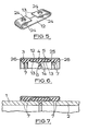
- the strip is flat and has teeth-like formations 24 in the central portion 12 and each end portion 13 produced by piercing the strip such that holes are made with jagged edges which protrude from one surface of the strip. These formations 24 are conveniently provided whilst the strip is in the plain flat state before being bent to the C-shape.
- the gasket 3 made of flexible synthetic rubber or other insulating material, has a plain cylindrical exterior. From its internal surface project an annular intermediate rib 6 of rectangular section and pairs of shallower ribs 7 adjacent the ends of the gasket, each of the latter ribs being of right-angled triangular shape having the hypotenuse sloping axially inwardly of the gasket.
- Clamp 5 comprises a stainless steel band 25 bent to almost a closed circular form and which has its circumferential edges 26 turned radially inwardly a distance slightly greater than the wall thickness of the gasket. Opposite ends of the band 25, not shown, are bent radially outwards to form flanges which are connected by clamping screws, not shown, for drawing the flanges together to contract the band radially.
- the band fits about the gasket 3. Its inturned circumferential edges 26 overlap the ends of the gasket to retain the gasket within the band.
- the gap between the flanged ends of the band is spanned by an arcuate plate, not shown, which is fixed to the inside of the band at one of the ends and slidingly lies against the inside surface of the other end.
- a bridge element 4 made from stainless steel strip is fixed to the gasket 3. As illustrated the bridge element is similar to that shown in Figures 2 and 3 but it may take one of the other forms described above and illustrated.
- the bridge element is applied to the intermediate portion of the gasket such that its central portion 12 is at the outside of the gasket, lying on the external surface, and its end portions 13 are at the inside of the gasket against the internal surface at opposite sides of the intermediate rib 6. Teeth 14 of the end portions 13 project inwardly towards the centre of the gasket.
- the bridge element 4 In assembling the joint, the bridge element 4 having first been fixed to the gasket and the clamp loosely fitted on the gasket, the pipes 1, 2 to be connected are entered into the opposite ends of the gasket until their end faces abut against the intermediate rib, as shown in Figure 7.
- the ribs 7 at the ends of the gasket are deflected axially inwardly of the gasket and grip the pipes as the pipes are pushed past them.
- the end portions 13 of the bridge element respectively lie on the pipes and their teeth 14 engage the surfaces of the pipes.
- the band 25 of the clamp is tightened about the gasket the gasket is sealingly compressed on to the pipes and the bridge element is urged tightly against the pipes, the teeth 14 digging into the pipes.
- the band is urged against the central portion 12 of the bridge element. Electrical continuity is thereby established by the bridge element between the pipes and between the clamps and the pipes.
Landscapes
- Engineering & Computer Science (AREA)
- General Engineering & Computer Science (AREA)
- Mechanical Engineering (AREA)
- Flanged Joints, Insulating Joints, And Other Joints (AREA)
- Clamps And Clips (AREA)
Applications Claiming Priority (2)
| Application Number | Priority Date | Filing Date | Title |
|---|---|---|---|
| GB08411590A GB2158173B (en) | 1984-05-05 | 1984-05-05 | Pipe-joints - electrical continuity |
| GB8411590 | 1984-05-05 |
Publications (1)
| Publication Number | Publication Date |
|---|---|
| EP0165691A1 true EP0165691A1 (fr) | 1985-12-27 |
Family
ID=10560563
Family Applications (1)
| Application Number | Title | Priority Date | Filing Date |
|---|---|---|---|
| EP85303157A Ceased EP0165691A1 (fr) | 1984-05-05 | 1985-05-03 | Pièces de liaison de tuyaux sans emboîtement |
Country Status (3)
| Country | Link |
|---|---|
| US (1) | US4659870A (fr) |
| EP (1) | EP0165691A1 (fr) |
| GB (1) | GB2158173B (fr) |
Cited By (5)
| Publication number | Priority date | Publication date | Assignee | Title |
|---|---|---|---|---|
| EP0501667A3 (en) * | 1991-02-23 | 1992-11-25 | Glynwed Consumer & Building Products Limited | Pipe coupling |
| EP0978678A1 (fr) * | 1998-08-06 | 2000-02-09 | Daume, Karin | Collier de serrage conductible pour tuyaux ou câbles |
| WO2000008369A1 (fr) * | 1998-08-06 | 2000-02-17 | Karin Daume Maschinenteile Gmbh & Co. Kg | Colliers electriquement conducteurs pour tuyaux et cables |
| EP0987483A1 (fr) * | 1998-09-15 | 2000-03-22 | Daume, Karin | Collier de serrage conductible pour tuyaux ou cables |
| WO2000015996A1 (fr) * | 1998-09-15 | 2000-03-23 | Karin Daume Maschinenteile Gmbh & Co. Kg | Collier de tube ou de cable electroconducteur |
Families Citing this family (36)
| Publication number | Priority date | Publication date | Assignee | Title |
|---|---|---|---|---|
| US5078613A (en) * | 1990-06-20 | 1992-01-07 | Newton Instrument Company | System for grounding telecommunications cable rack assembly and the like |
| US5190322A (en) * | 1991-09-06 | 1993-03-02 | Chrysler Corp | Sealing cuff for blow molded plastic components |
| US5951812A (en) * | 1997-05-23 | 1999-09-14 | A. O. Smith Corporation | Joining member and method of joining two conductive pieces of fiberglass reinforced plastic pipe |
| RU2134004C1 (ru) * | 1998-01-21 | 1999-07-27 | Российский Федеральный Ядерный Центр - Всероссийский Научно-Исследовательский Институт Экспериментальной Физики | Токопроводящее соединение |
| DE10004671B4 (de) * | 2000-02-03 | 2007-07-19 | Karin Daume Maschinenteile Gmbh & Co. Kg | Einrichtung zum elektrisch leitenden Kontaktieren eines elektrisch leitenden Teiles eines insbesondere länglichen, beispielsweise im wesentlichen zylindrischen Körpers, beispielsweise eines Rohres oder eines Kabels |
| ES2211576T3 (es) | 2000-02-03 | 2004-07-16 | DAUME PATENTBESITZGESELLSCHAFT MBH & CO. KG | Brida electroconductora para tubos o cables. |
| DE10031101A1 (de) * | 2000-06-30 | 2002-01-24 | Daume Karin Maschinenteile | Einrichtung zum elektrisch leitenden Kontaktieren eines elektrisch leitenden Teiles eines insbesondere länglichen, beispielsweise im wesentlichen Zylindrischen Körpers, beispielsweise eines Rohres oder eines Kabels |
| DE10004887A1 (de) | 2000-02-04 | 2001-08-23 | Daume Karin Maschinenteile | Einrichtung zum Kontaktieren von insbesondere länglichen, bspw. im wesentlichen zylindrischen Körpern, bspw. Rohren oder Kabeln |
| AU2000267008A1 (en) * | 2000-06-30 | 2002-01-14 | Daume Patentbesitzgesellschaft mbH and Co. KG | Electrically conductive pipe or cable clip |
| GB0017355D0 (en) * | 2000-07-15 | 2000-08-30 | Imi Yorkshire Fittings | Improvements relating to push-in tube fittings |
| DE20101067U1 (de) * | 2001-01-19 | 2001-05-10 | Karin Daume Maschinenteile GmbH & Co. KG, 30938 Burgwedel | Einrichtung zum elektrisch leitenden Kontaktieren eines abisolierten Außenleiters eines Koaxialkabels |
| US6755675B2 (en) * | 2001-11-12 | 2004-06-29 | Itt Manufacturing Enterprises, Inc. | Fluid quick connector with secure electrical ground contact |
| US6863312B1 (en) | 2003-10-02 | 2005-03-08 | Mark K. Liebst | Pipe connector assembly |
| US8092129B2 (en) | 2006-04-21 | 2012-01-10 | Hubbell Incorporated | Bonding washer |
| US7575447B2 (en) * | 2006-10-13 | 2009-08-18 | Airbus Deutschland Gmbh | Arrangement for connection of pipes |
| CA2705351C (fr) * | 2007-10-03 | 2014-01-21 | Anvil International, Lp | Joints de raccords et procedes associes |
| WO2009097544A2 (fr) * | 2008-01-30 | 2009-08-06 | Breeze-Torca Products, Llc | Serre-joint à sangle à boulon unique doté d'une nervure centrale à joints et joint à recouvrement de tuyau utilisant le serre-joint |
| US8864181B2 (en) * | 2011-02-16 | 2014-10-21 | Sensus Spectrum, Llc | Split-ring gland pipe coupling with corrugated armor |
| US8748748B2 (en) * | 2011-03-01 | 2014-06-10 | Kirkhill-Ta Co. | Clamp assembly and conductive cushion with molded-in grounding foil |
| US20130139870A1 (en) | 2011-12-02 | 2013-06-06 | Cooper Technologies Company | Pier connection sytem for pier caps of photovoltaic system |
| US8701372B2 (en) | 2011-12-02 | 2014-04-22 | Cooper Technologies Company | Clip fastener for photovoltaic system |
| US8726587B2 (en) | 2011-12-02 | 2014-05-20 | Cooper Technologies Company | Module rail for photovoltaic system |
| US8960729B2 (en) * | 2011-12-15 | 2015-02-24 | Eliezer Krausz Industrial Development Ltd. | Clamp assembly with annular clamps and bridge |
| US20130316601A1 (en) * | 2012-05-24 | 2013-11-28 | Cablofil, Inc. | Bonding clip |
| JP6478925B2 (ja) * | 2013-02-22 | 2019-03-06 | イートン コーポレーションEaton Corporation | ホースアセンブリ用のフレキシブル接点構造 |
| US9065191B2 (en) | 2013-02-25 | 2015-06-23 | Hubbell Incorporated | Single fastener electrical connector |
| US8888431B2 (en) | 2013-03-15 | 2014-11-18 | Hubbell Incorporated | Adjustable bonding washer |
| CN104134890A (zh) * | 2013-05-02 | 2014-11-05 | 辉达公司 | 电子设备及用于电子设备中的插座连接器 |
| BE1021364B1 (nl) * | 2013-12-17 | 2015-11-06 | Atlas Copco Airpower Naamloze Vennootschap | Koppeling voor het verbinden van buisuiteinden en overbrugging voor gebruik in een koppeling |
| FR3001276B1 (fr) * | 2014-04-14 | 2015-08-14 | Parker Hannifin Mfg France Sas | Dispositif de raccordement assurant une continuite electrique entre tubes |
| CN105299355A (zh) * | 2014-06-13 | 2016-02-03 | 陕西飞机工业(集团)有限公司 | 一种飞机上风道管的连接结构 |
| EP2977663B1 (fr) * | 2014-07-24 | 2018-05-02 | Marco Zambolin | Collier de connection pour extremite de tubes |
| US9520657B2 (en) | 2014-07-31 | 2016-12-13 | Hubbell Incorporated | Electrical terminal |
| GB2563676B (en) * | 2017-06-23 | 2022-05-18 | Saint Gobain Pont A Mousson | Gripping collar and corresponding tubular joint |
| WO2020092250A1 (fr) | 2018-10-29 | 2020-05-07 | Hubbell Incorporated | Rondelle de liaison |
| CN115004480A (zh) | 2019-12-30 | 2022-09-02 | 哈勃股份有限公司 | 结合夹具 |
Citations (4)
| Publication number | Priority date | Publication date | Assignee | Title |
|---|---|---|---|---|
| US4060301A (en) * | 1974-03-12 | 1977-11-29 | Beatty Albert W | Electrical connector for transmission line insulators |
| US4215883A (en) * | 1979-04-11 | 1980-08-05 | Brown Theodore C Sr | Coupling for pipes and fittings |
| US4316053A (en) * | 1979-09-24 | 1982-02-16 | Coupling Systems, Inc. | Pipe couplings and coupling gaskets |
| US4465330A (en) * | 1980-01-17 | 1984-08-14 | Cenzo Herbert A De | Clam-shell coupling for joining beaded tubes |
Family Cites Families (13)
| Publication number | Priority date | Publication date | Assignee | Title |
|---|---|---|---|---|
| FR852854A (fr) * | 1938-04-13 | 1940-03-05 | Trist & Co Ltd Ronald | Perfectionnements aux raccords de tuyaux |
| US2273398A (en) * | 1941-05-02 | 1942-02-17 | Flex O Tube Company | Flexible hose coupling |
| US2376017A (en) * | 1942-07-25 | 1945-05-15 | Smallpeice Cosby Dona Philipps | Gland |
| US2796457A (en) * | 1952-06-23 | 1957-06-18 | Walter E Stinger | R-f gasket for radio interference attenuation |
| US2753392A (en) * | 1952-12-05 | 1956-07-03 | Edward S Hebeler | Cable connections |
| US2966539A (en) * | 1957-10-07 | 1960-12-27 | American Cast Iron Pipe Co | Electrically conductive pipe joint and gasket |
| US3116078A (en) * | 1961-07-18 | 1963-12-31 | Bernard F Scherer | Coupling having annularly arranged u-shaped gripping members retained against movement in sleeve |
| US3217092A (en) * | 1963-06-13 | 1965-11-09 | Amsted Ind Inc | Clip for electrical conducting pipe joint |
| US3453006A (en) * | 1966-03-28 | 1969-07-01 | C & L Ind Inc | Conduit coupling |
| GB1230377A (fr) * | 1967-06-15 | 1971-04-28 | ||
| US3479066A (en) * | 1967-07-03 | 1969-11-18 | Morris Gittleman | Pipe coupling |
| SU538190A1 (ru) * | 1975-03-24 | 1976-12-05 | Соединение труб | |
| US4346428A (en) * | 1980-06-05 | 1982-08-24 | Stanley Aviation Corp. | Coupling assembly with bonding jumper |
-
1984
- 1984-05-05 GB GB08411590A patent/GB2158173B/en not_active Expired
-
1985
- 1985-05-03 US US06/730,684 patent/US4659870A/en not_active Expired - Fee Related
- 1985-05-03 EP EP85303157A patent/EP0165691A1/fr not_active Ceased
Patent Citations (4)
| Publication number | Priority date | Publication date | Assignee | Title |
|---|---|---|---|---|
| US4060301A (en) * | 1974-03-12 | 1977-11-29 | Beatty Albert W | Electrical connector for transmission line insulators |
| US4215883A (en) * | 1979-04-11 | 1980-08-05 | Brown Theodore C Sr | Coupling for pipes and fittings |
| US4316053A (en) * | 1979-09-24 | 1982-02-16 | Coupling Systems, Inc. | Pipe couplings and coupling gaskets |
| US4465330A (en) * | 1980-01-17 | 1984-08-14 | Cenzo Herbert A De | Clam-shell coupling for joining beaded tubes |
Cited By (8)
| Publication number | Priority date | Publication date | Assignee | Title |
|---|---|---|---|---|
| EP0501667A3 (en) * | 1991-02-23 | 1992-11-25 | Glynwed Consumer & Building Products Limited | Pipe coupling |
| EP0978678A1 (fr) * | 1998-08-06 | 2000-02-09 | Daume, Karin | Collier de serrage conductible pour tuyaux ou câbles |
| WO2000008369A1 (fr) * | 1998-08-06 | 2000-02-17 | Karin Daume Maschinenteile Gmbh & Co. Kg | Colliers electriquement conducteurs pour tuyaux et cables |
| AU741870B2 (en) * | 1998-08-06 | 2001-12-13 | Karin Daume Maschinenteile Gmbh & Co. Kg | Electro-conductive tube or cable clamp |
| EP0987483A1 (fr) * | 1998-09-15 | 2000-03-22 | Daume, Karin | Collier de serrage conductible pour tuyaux ou cables |
| WO2000015996A1 (fr) * | 1998-09-15 | 2000-03-23 | Karin Daume Maschinenteile Gmbh & Co. Kg | Collier de tube ou de cable electroconducteur |
| AU741863B2 (en) * | 1998-09-15 | 2001-12-13 | Karin Daume Maschinenteile Gmbh & Co. Kg | Electrically conductive pipe clip or cable clip |
| US6441303B1 (en) | 1998-09-15 | 2002-08-27 | Karin Daume Maschinenteile, Gmbh & Co. Kg | Device for electrically contacting and sealing a tubular member |
Also Published As
| Publication number | Publication date |
|---|---|
| GB2158173B (en) | 1987-10-28 |
| GB2158173A (en) | 1985-11-06 |
| US4659870A (en) | 1987-04-21 |
| GB8411590D0 (en) | 1984-06-13 |
Similar Documents
| Publication | Publication Date | Title |
|---|---|---|
| US4659870A (en) | Socket-less pipe joints | |
| US4480860A (en) | Transition coupling and clamp assembly containing same | |
| US4026586A (en) | Plain end pipe joint | |
| US4155574A (en) | Simplified pipe coupling | |
| US4380348A (en) | Pipe clamping assembly | |
| US3982779A (en) | Clamps for joining tubes or tubular structural members | |
| US4429907A (en) | Pipe coupler | |
| AU678444B2 (en) | Pipe coupling | |
| US5104159A (en) | Threadless coupling for pipes and an air-tight inner cylinder therefor | |
| US4538839A (en) | Pipe joint coupling | |
| JP2755257B2 (ja) | ホースクリップ | |
| KR100317304B1 (ko) | 관이음구 | |
| US4473246A (en) | Pipe coupling | |
| US3533650A (en) | Pipe clamp for plastic or thin walled pipe | |
| US4124236A (en) | Coupling for helically corrugated spiral pipe | |
| US5015015A (en) | Clip securing arrangement for ventilation systems | |
| US5842725A (en) | Clamp as well as pipe connection with a clamp | |
| US3315991A (en) | Pipe coupling | |
| US5549334A (en) | Retaining band assembly for internal pipe seals | |
| AU659851B2 (en) | Universal saddle tee for pipes | |
| US5166475A (en) | Pipe flange connections having improved conductivity thereacross | |
| US20050099003A1 (en) | Gasket for acid waste couplings | |
| AU741863B2 (en) | Electrically conductive pipe clip or cable clip | |
| US5356306A (en) | Metal conductor element | |
| JP3417689B2 (ja) | 管継手 |
Legal Events
| Date | Code | Title | Description |
|---|---|---|---|
| PUAI | Public reference made under article 153(3) epc to a published international application that has entered the european phase |
Free format text: ORIGINAL CODE: 0009012 |
|
| AK | Designated contracting states |
Designated state(s): AT BE CH DE FR IT LI LU NL SE |
|
| 17P | Request for examination filed |
Effective date: 19860220 |
|
| 17Q | First examination report despatched |
Effective date: 19870422 |
|
| STAA | Information on the status of an ep patent application or granted ep patent |
Free format text: STATUS: THE APPLICATION HAS BEEN REFUSED |
|
| 18R | Application refused |
Effective date: 19881031 |
|
| RIN1 | Information on inventor provided before grant (corrected) |
Inventor name: JONES, CONRAD DAVID |