EP0165702B1 - Dispositif pour empêcher une utilisation illicite d'enregistreurs à cassette et/ou d'appareils de reproduction - Google Patents
Dispositif pour empêcher une utilisation illicite d'enregistreurs à cassette et/ou d'appareils de reproduction Download PDFInfo
- Publication number
- EP0165702B1 EP0165702B1 EP19850303413 EP85303413A EP0165702B1 EP 0165702 B1 EP0165702 B1 EP 0165702B1 EP 19850303413 EP19850303413 EP 19850303413 EP 85303413 A EP85303413 A EP 85303413A EP 0165702 B1 EP0165702 B1 EP 0165702B1
- Authority
- EP
- European Patent Office
- Prior art keywords
- cassette
- playback apparatus
- dummy
- members
- dummy cassette
- Prior art date
- Legal status (The legal status is an assumption and is not a legal conclusion. Google has not performed a legal analysis and makes no representation as to the accuracy of the status listed.)
- Expired
Links
- 230000007246 mechanism Effects 0.000 claims abstract description 11
- 230000005540 biological transmission Effects 0.000 claims abstract description 7
- 238000003780 insertion Methods 0.000 claims abstract description 5
- 230000037431 insertion Effects 0.000 claims abstract description 5
- 230000003213 activating effect Effects 0.000 claims description 9
- 230000003993 interaction Effects 0.000 claims 1
- 230000008859 change Effects 0.000 description 2
- 239000000463 material Substances 0.000 description 2
- 239000002184 metal Substances 0.000 description 2
- 230000009471 action Effects 0.000 description 1
- 239000011324 bead Substances 0.000 description 1
- 230000006835 compression Effects 0.000 description 1
- 238000007906 compression Methods 0.000 description 1
- 238000010276 construction Methods 0.000 description 1
- 238000006073 displacement reaction Methods 0.000 description 1
- 230000006872 improvement Effects 0.000 description 1
- 238000012423 maintenance Methods 0.000 description 1
- 238000000034 method Methods 0.000 description 1
- 230000008707 rearrangement Effects 0.000 description 1
Images

Classifications
-
- G—PHYSICS
- G11—INFORMATION STORAGE
- G11B—INFORMATION STORAGE BASED ON RELATIVE MOVEMENT BETWEEN RECORD CARRIER AND TRANSDUCER
- G11B33/00—Constructional parts, details or accessories not provided for in the other groups of this subclass
- G11B33/02—Cabinets; Cases; Stands; Disposition of apparatus therein or thereon
- G11B33/06—Cabinets; Cases; Stands; Disposition of apparatus therein or thereon combined with other apparatus having a different main function
-
- G—PHYSICS
- G11—INFORMATION STORAGE
- G11B—INFORMATION STORAGE BASED ON RELATIVE MOVEMENT BETWEEN RECORD CARRIER AND TRANSDUCER
- G11B33/00—Constructional parts, details or accessories not provided for in the other groups of this subclass
- G11B33/005—Means for locking the disc or cassette receiving slot, e.g. dummy cassettes locked in the slot
-
- Y—GENERAL TAGGING OF NEW TECHNOLOGICAL DEVELOPMENTS; GENERAL TAGGING OF CROSS-SECTIONAL TECHNOLOGIES SPANNING OVER SEVERAL SECTIONS OF THE IPC; TECHNICAL SUBJECTS COVERED BY FORMER USPC CROSS-REFERENCE ART COLLECTIONS [XRACs] AND DIGESTS
- Y10—TECHNICAL SUBJECTS COVERED BY FORMER USPC
- Y10T—TECHNICAL SUBJECTS COVERED BY FORMER US CLASSIFICATION
- Y10T70/00—Locks
- Y10T70/40—Portable
-
- Y—GENERAL TAGGING OF NEW TECHNOLOGICAL DEVELOPMENTS; GENERAL TAGGING OF CROSS-SECTIONAL TECHNOLOGIES SPANNING OVER SEVERAL SECTIONS OF THE IPC; TECHNICAL SUBJECTS COVERED BY FORMER USPC CROSS-REFERENCE ART COLLECTIONS [XRACs] AND DIGESTS
- Y10—TECHNICAL SUBJECTS COVERED BY FORMER USPC
- Y10T—TECHNICAL SUBJECTS COVERED BY FORMER US CLASSIFICATION
- Y10T70/00—Locks
- Y10T70/50—Special application
- Y10T70/5611—For control and machine elements
- Y10T70/5681—Gear
Definitions
- This invention relates to a safety arrangement for preventing the unauthorised use of cassette recording and/or playback apparatus, such as audio cassette players, video recorders and/or reproduction devices, having a slot or opening into which a cassette is inserted.
- the cassettes normally contain one or more spools carrying polymeric tapes coated with a thin layer of magnetisable material.
- the safety arrangement comprises a dummy cassette adapted for insertion into the audio cassette player or video recorder, for example when the player or recorder is to be left unattended e.g. in a public place; and acts as a deterrent against theft of the player or recorder.
- the dummy cassette consists of a casing having an externally operable mechanism within its walls which activates locking means whereby the cassette cannot be removed without catastrophic damage to the player or recorder.
- Dummy cassettes of this nature render apparatus in which they are locked unattractive to thieves since the apparatus is virtually useless unless a means can be found to remove the dummy cassette without damaging the apparatus.
- Such cassettes also prevent unauthorised use of the apparatus e.g. the viewing of tapes which are to be used in legal proceedings or whose content has a high security classification.
- United Kingdom patent specification no. 1,570,616 describes a device for use in preventing unauthorised use of a tape recorder, comprising a body shaped and adapted to be inserted into the cassette-receiving cavity of a recorder, the body carrying latching means which can be operated to change from a first condition in which the device can be inserted into a recorder cassette-receiving cavity, to a second condition in which after such insertion the device is mechanically latched in the cavity such as to prevent removal of the device from the cavity, the latching means including a locking mechanism operable by a user of the device to lock the latching means in said second condition.
- a disadvantage of the dummy cassette described in the above publication is that it may not conform to the tolerances used for the standard dimensions of audio and/or video recording and replaying apparatus. For this reason such dummy cassettes cannot be used in all commercial equipment without the risk of damage.
- the locking mechanism interacts with the inside of the cassette-receiving cavity which varies in structure from manufacturer to manufacturer. Furthermore in some cases the locking mechanism may damage the recording apparatus into which it is inserted when locked.
- An object of the present invention is to provide an improvement on the known technique with an arrangement which can readily be manufactured and which requires relatively little or no service.
- a further object is to provide an arrangement which fulfills all safety requirements, and which can also be used in conjunction with practically all types of recording and playback apparatus available on the market.
- the invention is characterised in that the transmission means is adapted to operate sleeve-like members in a manner to cause the sleeve-like members to move from a passive or inactive position within the dummy cassette through openings arranged in a casing part of said device and to embrace the drive shafts of the recording and/or playback apparatus.
- a conventional cassette type playback apparatus includes a cassette receiving cavity 10.
- the apparatus may be portable or intended as a permanent fixture in an automotive vehicle or boat and intended for reproducing and, optionally, reproducing sound.
- the playback apparatus may also be a video-tape reproduction of known kind.
- the cavity 10 contains an elongated rectangular dummy cassette 11 which has been inserted into it in the direction denoted by the arrow A.
- the outer part of the cassette 11 is made of a robust sheet material such as sheet metal.
- the dummy cassette 11 has an external shape and dimensions which are compatible with standard tape cassettes, e.g. Betamax, VHS, Philips 2000 etc.
- the cassette body is made from two separable cassette halves 12 and 13 which have a cavity between them.
- this cavity accomodates magnetic recording tape and the externally driveable shafts each of which carries a tape spool.
- One half of the dummy cassette casing 12 exhibits two recesses 18, 19 arranged sequentially in the longitudinal direction, and a plate 20 arranged between the openings and covering them.
- a key or some other activating means 14 can be inserted into a lock cylinder 15 of a known kind which, upon rotating of the key 14, synchronously rotates a shaft 16 forming an extension of the lock cylinder 15 and operatively coacting with it.
- the free end of the shaft 16 is connected with one end of an arcuate or bowed elongate element 17 which extends transversely from the shaft 16.
- the other end of the element 17 is seated firmly at the bottom of the casing half 12 of the dummy cassette 11, either directly or indirectly.
- the elongate element 17 is arranged to lie above the plate 20 and will normally show some degree of slack, which can be taken up, when the key 14 is turned.
- the openings 18, 19 in the cassette half 12 of the dummy cassette 11 are arranged to accomo- date moveable sleeve-like members 18' and 19' respectively which, when occupying their inactive position, extend completely through or substantially completely through the space formed between the two halves of the cassette 11 and 12.
- the sleeve-like members 18' and 19' are biased by respective springs 18" and 19" in a manner such that the members 18' and 19' are normally urged against the undersurface of the plate 20, for example as shown in Figure 2-A.
- the springs 18" and 19" may take the form of thrust springs which endeavour to take the passive position, illustrated in Figure 2-A, in which the lower edges of the sleeve-like members 18' and 19' are flush with or substantially flush with the undersurface of the cassette half 12.
- the sleeve-like members are thus located within the space between the two halves 12 and 13 of the dummy cassette when inactive.
- the above arrangement operates as follows when it is desired to lock the dummy cassette 11 into the cassette receiving cavity 10.
- the dummy cassette 11 is inserted into the cavity 10 of the playback apparatus, e.g. a cassette sound and/or video recorder/playback device, in conventional manner.
- the key or similar lock activating means 14 is placed in the lock cylinder 15 and turned in the direction shown by the arrow B, see Figure 1. Rotation of the key 14 causes the shaft 16 to rotate in the same direction so that the elongated element 17 is stretched or tensioned and presses down against the plate 20.
- the sleeve-like members 18' and 19' will then be in their final position and protrude out of the cassette half 12 and able to embrace the drive shafts, not shown, of the playback apparatus.
- the key 14 is withdrawn from the lock cylinder 15 and the dummy cassette is firmly locked into the playback apparatus.
- the device described with reference to and as illustrated in Figures 1 and 2 can be used with the majority of cassette players and video reproduction devices available at the present time.
- the simple construction provides an efficient locking mechanism which require little or no service or maintenance.
- the outer dimensions of the case 11 of the dummy cassette and the location of the sleeve-like members 18' and 19' should conform to the standard dimensions for the cassette receiving cavity and the drive shaft positions in the playback apparatus.
- the dimensions and the sleeve-like member locations may conform to the standard dimensions laid down for the well-known VHS, Betamax or V2000 systems.
- Other standards exist both for video and sound recording cassettes and the dummy cassettes according to the invention may be configured to meet these standards.
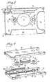
- the second embodiment of the playback device locking arrangement illustrated in Figure 3 and in the expolded view in Figure 4 has pricipally the same mode of operation as the arrangement previously described with respect to Figures 1 and 2.
- the second embodiment uses a different mechanical arrangement to move the sleeve-like members into their active, locking, position. This arangement is intended for use in playback apparatus of the kind in which the whole of the cassette, in an active playback position, is oriented within the playback apparatus and in which one or more edge portions of the cassette may be arranged to activate switch means for switching the apparatus into its playback mode.
- the locking arrangement illustrated in Figures 3 and 4 has a thickness corresponding to a conventional cassette.
- the outer shape differs from that of a conventional cassette, for reasons hereinafter made apparent.
- the dummy cassette 31 can be inserted into a playback apparatus, shown in chain lines at 32, in the direction of the arrow as beforedescribed, and comprises two mutually connectable elongate rectangular casing parts 40, 41, which define a cavity therebetween.
- a lock cylinder 33 Arranged in the cavity between the casing parts 40, 41 is a lock cylinder 33 which is adapted to co-act with an activating means or key, indicated at 34.
- the whole of the lock cylinder is located within said cavity and communicates with the outer side of the casing 31 through the keyhole located on the short side of the casing.
- the lock cylinder 33 merges with a rotatable shaft 35 inserted in a hollow cylindrical elongated rack member 35' having teeth 35" arranged along the whole of its length on the outer surface thereof.
- the shaft 35 and thus also the lock cylinder part 33, is held against displacement relative to the rack element 35'.
- the lock cylinder 33, the shaft 35 and the rack element 35' therewith form an assembly which can be moved axially backwards and forwards in the direction of the arrow C ( Figure 4).
- this assembly can be moved axially along a path 36 with the aid of the key 34, the teeth 35" on the rack element being adapted to co-act with corresponding teeth on a centrally arranged toothed wheel or cog 37 arranged for rotation on a shaft 37'.
- a respective toothed wheel or cog 38 and 39 firmly mounted on one end of an associated sleeve 38', 39'.
- the sleeves 38', 39' with associated cog wheel 38, 39 are arranged in one position to embrace upstanding cylindrical pegs 42,43 arranged on the bottom of the casing part 41, each of the pegs presenting a respective helical groove 42', 43'.
- the height of the teeth on the cog wheel 37 corresponds substantially to the height of the pegs 42, 43, while the height of the teeth on the laterally placed cog wheels 38, 39 are considerably shorter.
- the sleeves 38' and 39' accommodating respective cog wheels 38, 39 are provided with an internal bead or like raised portion, indicated at 46 and 47, having a configuration corresponding to the configuration of the helical grooves 42', 43'.
- the cassette casing part 40 presents two through openings 44, 45 arranged in the same vertical plane as the stationary pegs 42, 43.
- a pin 49 which, when the activating means 34 and therewith also the shaft 35 are rotated, is arranged to engage in a recess 49'.
- the lock mechanism 33 of this embodiment is also arranged to be locked in the aforedescribed active position in a known manner, it being necessary to have access to the activating means 34 in order to release the lock.
- the lock arrangement illustrated in Figures 3 and 4 also includes a laterally arranged recess 50 intended when using the aforementioned type of playback apparatus for sound cassettes to eliminate drive release of the playback apparatus.
- the recess 51 is intended for eliminating the recoupling means of the playback apparatus. These recesses 50 and 51 may eliminate, for example, operation of the release function of the playback apparatus.
- the aforedescribed arrangement can also be combined with an alarm system in some suitable manner.
- alarm systems can be activated when attempts are made to remove the dummy cassette when locked or by movement or vibration of the assembly.
- the dummy cassette is preferably constructed from metal which will assist in .preventing damage to the playback apparatus.
- the described embodiments show the locking means and key entry made from the short edge of the rectangular cassette body. Where necessary, for instance when recorder or playback configuration dictates it, the key entry may be made from the long edge of the rectangular dummy cassette body. Such a change will necessitate a rearrangement of the internal elements of the locking system which would cause no difficulty for a person skilled in this art.
Landscapes
- Feeding And Guiding Record Carriers (AREA)
- Casings For Electric Apparatus (AREA)
- Automatic Tape Cassette Changers (AREA)
- Packaging Of Annular Or Rod-Shaped Articles, Wearing Apparel, Cassettes, Or The Like (AREA)
- Signal Processing Not Specific To The Method Of Recording And Reproducing (AREA)
- Fittings On The Vehicle Exterior For Carrying Loads, And Devices For Holding Or Mounting Articles (AREA)
Claims (8)
Priority Applications (1)
| Application Number | Priority Date | Filing Date | Title |
|---|---|---|---|
| AT85303413T ATE38449T1 (de) | 1984-05-16 | 1985-05-15 | Vorrichtung zum verhindern einer unberechtigten benutzung von kassettenrecordern und/oder wiedergabegeraeten. |
Applications Claiming Priority (2)
| Application Number | Priority Date | Filing Date | Title |
|---|---|---|---|
| SE8402635A SE456956B (sv) | 1984-05-16 | 1984-05-16 | Saekerhetsanordning foer avspelningsapparater |
| SE8402635 | 1984-05-16 |
Publications (2)
| Publication Number | Publication Date |
|---|---|
| EP0165702A1 EP0165702A1 (fr) | 1985-12-27 |
| EP0165702B1 true EP0165702B1 (fr) | 1988-11-02 |
Family
ID=20355896
Family Applications (1)
| Application Number | Title | Priority Date | Filing Date |
|---|---|---|---|
| EP19850303413 Expired EP0165702B1 (fr) | 1984-05-16 | 1985-05-15 | Dispositif pour empêcher une utilisation illicite d'enregistreurs à cassette et/ou d'appareils de reproduction |
Country Status (10)
| Country | Link |
|---|---|
| US (1) | US4656551A (fr) |
| EP (1) | EP0165702B1 (fr) |
| JP (1) | JPS60254435A (fr) |
| KR (1) | KR850008753A (fr) |
| AT (1) | ATE38449T1 (fr) |
| AU (1) | AU4246485A (fr) |
| BR (1) | BR8502285A (fr) |
| DE (1) | DE3566057D1 (fr) |
| IT (1) | IT1200476B (fr) |
| SE (1) | SE456956B (fr) |
Families Citing this family (8)
| Publication number | Priority date | Publication date | Assignee | Title |
|---|---|---|---|---|
| ES2011531A6 (es) * | 1987-12-10 | 1990-01-16 | Poyer Michael | Dispositivo de seguridad para aparatos grabadores o reproductores de cassettes de video. |
| DE3905647A1 (de) * | 1989-02-24 | 1990-08-30 | Datev Datenverarbeitungsorgani | Sperrvorrichtung fuer diskettenlaufwerk-schaechte |
| JP2946604B2 (ja) * | 1990-02-26 | 1999-09-06 | 株式会社デンソー | 交流発電機 |
| US5076461A (en) * | 1990-10-01 | 1991-12-31 | Playskool Baby, Inc. | Guard for cassette player |
| JP3014795B2 (ja) * | 1991-05-13 | 2000-02-28 | パイオニア株式会社 | 車載用記録媒体演奏装置 |
| GB2296597B (en) * | 1994-11-30 | 1998-10-28 | Terence Ronald Green | Anti-tamper device |
| EP0806770A1 (fr) * | 1996-05-10 | 1997-11-12 | Terence Ronald Green | Dispositif de protection contre utilisation non-autorisée |
| DE102004026850A1 (de) * | 2004-06-02 | 2005-12-29 | Hilti Ag | Einsteckende für ein drehendes und/oder schlagendes Werkzeug |
Family Cites Families (8)
| Publication number | Priority date | Publication date | Assignee | Title |
|---|---|---|---|---|
| US1441866A (en) * | 1923-01-09 | Multiple-control lock eor automobiles | ||
| JPS51138412A (en) * | 1975-05-26 | 1976-11-30 | Matsushita Electric Ind Co Ltd | Video tape recorder |
| SE391554B (sv) * | 1975-11-17 | 1977-02-21 | Telcefo Security Prod Ab | Sett att forhindra obehorigt utnyttjande av bandspelare jemte anordning for utovande av settet |
| US4188648A (en) * | 1978-09-05 | 1980-02-12 | Memorex Corporation | Data security apparatus for magnetic recording disc drive |
| JPS5875383U (ja) * | 1981-11-16 | 1983-05-21 | ティーディーケイ株式会社 | カセツトテ−プ |
| SE8200912L (sv) * | 1982-02-16 | 1983-08-17 | Indwest Ab | Anordning som er avsedd for kassettapparater |
| GB8303028D0 (en) * | 1983-02-03 | 1983-03-09 | Fechner J | Video theft alarm |
| GB2138778B (en) * | 1983-04-14 | 1986-08-28 | Cecil Thomas Dunne | Video cassette security device |
-
1984
- 1984-05-16 SE SE8402635A patent/SE456956B/sv not_active IP Right Cessation
-
1985
- 1985-05-06 US US06/731,054 patent/US4656551A/en not_active Expired - Fee Related
- 1985-05-14 IT IT2068385A patent/IT1200476B/it active
- 1985-05-14 AU AU42464/85A patent/AU4246485A/en not_active Abandoned
- 1985-05-15 BR BR8502285A patent/BR8502285A/pt unknown
- 1985-05-15 EP EP19850303413 patent/EP0165702B1/fr not_active Expired
- 1985-05-15 DE DE8585303413T patent/DE3566057D1/de not_active Expired
- 1985-05-15 AT AT85303413T patent/ATE38449T1/de not_active IP Right Cessation
- 1985-05-16 KR KR1019850003324A patent/KR850008753A/ko not_active Withdrawn
- 1985-05-16 JP JP60102818A patent/JPS60254435A/ja active Pending
Also Published As
| Publication number | Publication date |
|---|---|
| EP0165702A1 (fr) | 1985-12-27 |
| US4656551A (en) | 1987-04-07 |
| AU4246485A (en) | 1985-11-21 |
| JPS60254435A (ja) | 1985-12-16 |
| ATE38449T1 (de) | 1988-11-15 |
| IT1200476B (it) | 1989-01-18 |
| DE3566057D1 (en) | 1988-12-08 |
| SE8402635D0 (sv) | 1984-05-16 |
| BR8502285A (pt) | 1986-01-14 |
| SE8402635L (sv) | 1985-11-17 |
| KR850008753A (ko) | 1985-12-21 |
| SE456956B (sv) | 1988-11-14 |
| IT8520683A0 (it) | 1985-05-14 |
Similar Documents
| Publication | Publication Date | Title |
|---|---|---|
| CA1085943A (fr) | Methode et dispositif pour empecher l'utilisation non autorisee de magnetophones a cassette | |
| US5289914A (en) | Safety device for cassettes | |
| KR900010771Y1 (ko) | 테이프 카셋트 | |
| EP0165702B1 (fr) | Dispositif pour empêcher une utilisation illicite d'enregistreurs à cassette et/ou d'appareils de reproduction | |
| WO1989005510A1 (fr) | Dispositif de securite pour lecteur ou enregistreur video | |
| US3839736A (en) | Record tape cartridges | |
| KR930011696B1 (ko) | 테이프 카세트 | |
| US5673573A (en) | Anti-tamper device for audio and computer devices having cassette or diskette receiving slot | |
| US4188648A (en) | Data security apparatus for magnetic recording disc drive | |
| US4931770A (en) | Protection system | |
| EP0308172B1 (fr) | Appareil d'enregistrement/reproduction magnétique du type à cassette | |
| WO1985005725A1 (fr) | Dispositif pour cassette | |
| US4814749A (en) | Protection system | |
| GB2168522A (en) | Improvements in or relating to locks | |
| WO1988009553A1 (fr) | Cache pour support de stockage d'informations discoide | |
| JP3365205B2 (ja) | 電子機器 | |
| KR100207743B1 (ko) | 테이프 레코더의 허브 로킹 해제 장치 | |
| JP2616548B2 (ja) | テープカセット | |
| JPH0337051Y2 (fr) | ||
| JPH0244378Y2 (fr) | ||
| KR200170665Y1 (ko) | 비디오테이프레코더의 테이프로딩구조 | |
| WO1991004387A1 (fr) | Dispositif antivol | |
| CA2169573A1 (fr) | Contenant verrouillable pour cassettes et articles analogues | |
| KR950006947Y1 (ko) | 비디오 테이프 카세트의 릴 록킹장치 | |
| EP0362463A1 (fr) | Système de protection |
Legal Events
| Date | Code | Title | Description |
|---|---|---|---|
| PUAI | Public reference made under article 153(3) epc to a published international application that has entered the european phase |
Free format text: ORIGINAL CODE: 0009012 |
|
| AK | Designated contracting states |
Designated state(s): AT BE CH DE FR GB LI NL SE |
|
| 17P | Request for examination filed |
Effective date: 19860624 |
|
| 17Q | First examination report despatched |
Effective date: 19871222 |
|
| GRAA | (expected) grant |
Free format text: ORIGINAL CODE: 0009210 |
|
| AK | Designated contracting states |
Kind code of ref document: B1 Designated state(s): AT BE CH DE FR GB LI NL SE |
|
| PG25 | Lapsed in a contracting state [announced via postgrant information from national office to epo] |
Ref country code: SE Effective date: 19881102 Ref country code: NL Effective date: 19881102 Ref country code: LI Effective date: 19881102 Ref country code: FR Free format text: THE PATENT HAS BEEN ANNULLED BY A DECISION OF A NATIONAL AUTHORITY Effective date: 19881102 Ref country code: CH Effective date: 19881102 Ref country code: BE Effective date: 19881102 Ref country code: AT Effective date: 19881102 |
|
| REF | Corresponds to: |
Ref document number: 38449 Country of ref document: AT Date of ref document: 19881115 Kind code of ref document: T |
|
| REF | Corresponds to: |
Ref document number: 3566057 Country of ref document: DE Date of ref document: 19881208 |
|
| REG | Reference to a national code |
Ref country code: CH Ref legal event code: PL |
|
| EN | Fr: translation not filed | ||
| NLV1 | Nl: lapsed or annulled due to failure to fulfill the requirements of art. 29p and 29m of the patents act | ||
| PG25 | Lapsed in a contracting state [announced via postgrant information from national office to epo] |
Ref country code: GB Effective date: 19890515 |
|
| PLBE | No opposition filed within time limit |
Free format text: ORIGINAL CODE: 0009261 |
|
| STAA | Information on the status of an ep patent application or granted ep patent |
Free format text: STATUS: NO OPPOSITION FILED WITHIN TIME LIMIT |
|
| 26N | No opposition filed | ||
| GBPC | Gb: european patent ceased through non-payment of renewal fee | ||
| PG25 | Lapsed in a contracting state [announced via postgrant information from national office to epo] |
Ref country code: DE Effective date: 19900201 |