EP0165719B1 - Tampon pour applicateur de liquide - Google Patents
Tampon pour applicateur de liquide Download PDFInfo
- Publication number
- EP0165719B1 EP0165719B1 EP19850303619 EP85303619A EP0165719B1 EP 0165719 B1 EP0165719 B1 EP 0165719B1 EP 19850303619 EP19850303619 EP 19850303619 EP 85303619 A EP85303619 A EP 85303619A EP 0165719 B1 EP0165719 B1 EP 0165719B1
- Authority
- EP
- European Patent Office
- Prior art keywords
- layer
- fibers
- wick
- loosely woven
- fluid
- Prior art date
- Legal status (The legal status is an assumption and is not a legal conclusion. Google has not performed a legal analysis and makes no representation as to the accuracy of the status listed.)
- Expired - Lifetime
Links
- 239000012530 fluid Substances 0.000 title claims description 32
- 239000000463 material Substances 0.000 claims description 62
- 239000000835 fiber Substances 0.000 claims description 60
- 210000002268 wool Anatomy 0.000 claims description 10
- 229920000728 polyester Polymers 0.000 claims description 8
- -1 polytetrafluorethylene Polymers 0.000 claims description 8
- 229920001343 polytetrafluoroethylene Polymers 0.000 claims description 8
- 239000004760 aramid Substances 0.000 claims description 7
- 229920003235 aromatic polyamide Polymers 0.000 claims description 7
- 238000000034 method Methods 0.000 claims description 3
- 238000004891 communication Methods 0.000 claims description 2
- 229920000784 Nomex Polymers 0.000 description 14
- 239000004763 nomex Substances 0.000 description 14
- 239000002245 particle Substances 0.000 description 14
- 239000003921 oil Substances 0.000 description 13
- 239000004744 fabric Substances 0.000 description 11
- 239000000843 powder Substances 0.000 description 11
- 239000004809 Teflon Substances 0.000 description 8
- 229920006362 Teflon® Polymers 0.000 description 8
- 229920002545 silicone oil Polymers 0.000 description 7
- 238000011161 development Methods 0.000 description 4
- 239000008187 granular material Substances 0.000 description 4
- 239000000203 mixture Substances 0.000 description 3
- 238000012546 transfer Methods 0.000 description 3
- 238000009825 accumulation Methods 0.000 description 2
- 239000002131 composite material Substances 0.000 description 2
- 229910052736 halogen Inorganic materials 0.000 description 2
- 150000002367 halogens Chemical class 0.000 description 2
- 238000003384 imaging method Methods 0.000 description 2
- 230000001050 lubricating effect Effects 0.000 description 2
- 229910052751 metal Inorganic materials 0.000 description 2
- 239000002184 metal Substances 0.000 description 2
- 238000012545 processing Methods 0.000 description 2
- 229920002379 silicone rubber Polymers 0.000 description 2
- 239000004945 silicone rubber Substances 0.000 description 2
- 229920002994 synthetic fiber Polymers 0.000 description 2
- 239000010409 thin film Substances 0.000 description 2
- WZCQRUWWHSTZEM-UHFFFAOYSA-N 1,3-phenylenediamine Chemical compound NC1=CC=CC(N)=C1 WZCQRUWWHSTZEM-UHFFFAOYSA-N 0.000 description 1
- VEXZGXHMUGYJMC-UHFFFAOYSA-M Chloride anion Chemical compound [Cl-] VEXZGXHMUGYJMC-UHFFFAOYSA-M 0.000 description 1
- RYGMFSIKBFXOCR-UHFFFAOYSA-N Copper Chemical compound [Cu] RYGMFSIKBFXOCR-UHFFFAOYSA-N 0.000 description 1
- 229910052782 aluminium Inorganic materials 0.000 description 1
- XAGFODPZIPBFFR-UHFFFAOYSA-N aluminium Chemical compound [Al] XAGFODPZIPBFFR-UHFFFAOYSA-N 0.000 description 1
- 238000013459 approach Methods 0.000 description 1
- 230000015556 catabolic process Effects 0.000 description 1
- 239000000470 constituent Substances 0.000 description 1
- 229920001577 copolymer Polymers 0.000 description 1
- 229910052802 copper Inorganic materials 0.000 description 1
- 239000010949 copper Substances 0.000 description 1
- 238000006731 degradation reaction Methods 0.000 description 1
- 230000000593 degrading effect Effects 0.000 description 1
- KPUWHANPEXNPJT-UHFFFAOYSA-N disiloxane Chemical class [SiH3]O[SiH3] KPUWHANPEXNPJT-UHFFFAOYSA-N 0.000 description 1
- 125000000524 functional group Chemical group 0.000 description 1
- 238000010438 heat treatment Methods 0.000 description 1
- 150000002500 ions Chemical class 0.000 description 1
- 239000007769 metal material Substances 0.000 description 1
- 150000002739 metals Chemical class 0.000 description 1
- 239000002480 mineral oil Substances 0.000 description 1
- 235000010446 mineral oil Nutrition 0.000 description 1
- 229920000642 polymer Polymers 0.000 description 1
- 229920001296 polysiloxane Polymers 0.000 description 1
- 239000004810 polytetrafluoroethylene Substances 0.000 description 1
- 239000011148 porous material Substances 0.000 description 1
- 238000007711 solidification Methods 0.000 description 1
- 230000008023 solidification Effects 0.000 description 1
- 239000007921 spray Substances 0.000 description 1
- 239000000758 substrate Substances 0.000 description 1
- 239000012209 synthetic fiber Substances 0.000 description 1
- 230000032258 transport Effects 0.000 description 1
Images
Classifications
-
- G—PHYSICS
- G03—PHOTOGRAPHY; CINEMATOGRAPHY; ANALOGOUS TECHNIQUES USING WAVES OTHER THAN OPTICAL WAVES; ELECTROGRAPHY; HOLOGRAPHY
- G03G—ELECTROGRAPHY; ELECTROPHOTOGRAPHY; MAGNETOGRAPHY
- G03G15/00—Apparatus for electrographic processes using a charge pattern
- G03G15/20—Apparatus for electrographic processes using a charge pattern for fixing, e.g. by using heat
- G03G15/2003—Apparatus for electrographic processes using a charge pattern for fixing, e.g. by using heat using heat
- G03G15/2014—Apparatus for electrographic processes using a charge pattern for fixing, e.g. by using heat using heat using contact heat
- G03G15/2017—Structural details of the fixing unit in general, e.g. cooling means, heat shielding means
- G03G15/2025—Structural details of the fixing unit in general, e.g. cooling means, heat shielding means with special means for lubricating and/or cleaning the fixing unit, e.g. applying offset preventing fluid
Definitions
- This invention relates to a fluid applicator wick particularly, although not exclusively, useful in a fusing system used in an electrophotographic printing machine.
- the applicator wick is of the kind which includes a fluid retaining material and a covering material disposed in contact with at least one surface of the fluid retaining material.
- the applicator wick is used for applying release material to the surface of a fuser member used for permanently affixing toner to a copy sheet.
- a typical electrophotographic printing machine employs a photoconductive member that is charged to a substantially uniform potential so as to sensitize the surface thereof.
- the charged portion of the photoconductive member is exposed to a light image of an original document being reproduced. Exposure of the charged photoconductive member selectively dissappates the charge thereon, in the irradiated areas.
- the latent image is developed by bringing a developer material into contact therewith.
- the developer material comprises toner particles adhering triboelectrically to carrier granules.
- the toner particles are attracted from the carrier granules to the latent image to form a toner powder image on the photoconductive member.
- the toner powder image is then transferred from the photoconductive member to a copy sheet. Thereafter, the toner particles are heated to permanently fuse the powder image to the copy sheet.
- the toner particles have been permanently fused to the copy sheet by the simulanteous application of heat and pressure by a pair of rollers.
- the rollers are in pressure contact with one another with one of the rollers being heated. Fusing of the toner particles takes place when the proper combination of heat and contact pressure are provided.
- the copy sheet with the powder image thereon is passed through the nip between the rollers.
- toner particles will be offset from the copy sheet to the fuser roll.
- These toner particles are then subsequently transferred to the surface of the backup roll which is in pressure contact with the fuser roll, during periods of time when no copy sheet passes through the nip.
- the wick is generally used to dispense silicone oil, a functional siloxane fluid, mineral oil, or one of many other release fluids upon the external surface of the fuser member.
- the fuser wick may be a pad overlying and in contact with the heated fuser roll.
- the wick is made from two different layers, a first layer coming into contact with the surface of the fuser roller and metering precise amounts of fluid thereon. The other layer, in contact with the first layer, has high release fluid retention capabilities for supplying the first layer with fluid.
- Various types of wicks have been devised to meter the release fluid on to the surface of the fuser roller.
- US-A-3 745 972 describes a fusing system including a heated fuser roller and a backup pressure roller.
- An applicator roller conveys a thin film of silicone oil from a pan to a wick.
- the wick includes a Teflon layer contacting the heated fuser roll and a Nomex layer contacting the applicator roll.
- US-A-4 083 322 discloses a fusing system including a heated fuser roller and a back up roller.
- a wick assembly comprises a Nomex layer, a wool layer, and a porous wiper pad.
- the wiper pad contacts the fuser roll with the Nomex roller engaging both the wiper pad and an applicator roll.
- the applicator roll rotates in an oil reservoir.
- the wool layer contacts the surface of the Nomex layer opposed to the wiper pad. Both the Nomex layer and wool layer meter oil to the wiper pad which passes oil to the fuser roll.
- US-A-4 309 957 describes a wick for applying release fluids to a fuser roller.
- the wick includes a layer of fibrous Teflon needled into a layer of Nomex.
- the Teflon layer contacts the surface of the fuser roller with the Nomex layer engaging an applicator roll disposed in an oil reservoir.
- US-A-4 336 766 discloses a two ply wick. One layer of the wick is relatively thick with the other layer being relatively thin. The thick layer feeds oil to the thin layer contacting the fuser roll. Both layers are made from Nomex.
- the present invention is intended to provide a fluid applicator wick with good fluid applying properties and with extended working life.
- the invention accordingly provides a fluid applicator wick of the kind specified which is characterised in that the covering material comprises at least a first layer of fibers and a second layer of fibers with a thin, loosely woven layer of material gauze being interposed between said first layer of fibers and said second layer of fibers with at least a portion of the fibers of said first layer of fibers and said second layer of fibers being interlocked with said layer of loosely woven gauze material interposed therebetween.
- an apparatus for substantially permanently fusing a toner image to a sheet A backup roll is operatively associated with a fuser roll to define a nip through which the sheet with the unfused toner powder image thereon passes to fuse the toner image to the sheet.
- a wick meters oil onto the fuser roll from the oil reservoir.
- the wick has an oil retaining material in communication with an oil reservoir.
- the covering material has one surface thereof contacting at least one surface of the oil retaining material with the other surface thereof contacting the fuser roll to meter oil thereon.
- the covering material has at least a first layer of fibers and a second layer of fibers with a thin loosely woven layer of gauze material interposed therebetween. At least a portion of the fibers of the first layer and the second layer are interlocked with the layer of loosely woven gauze material interposed therebetween.
- An exemplary electrophotographic printing machine includes a belt have a photoconductive surface deposited on a conductive substrate.
- the belt advances successive portions of the photoconductive surface to various processing stations disposed about the path of movement thereof. Initially, a portion of the belt passes through a charging station.
- a corona generating device charges the photoconductive surface of the belt to a relatively high, substantially uniform potential. Thereafter, the charged portion of the photoconductive surface is advanced through the imaging station.
- an original document is positioned on a transparent platen. Lamps flash light rays onto the original document. The light rays reflected from the original document are transmitted through a lens forming a light image thereof.
- the lens focuses the light-image-onto the charged portion of the photoconductive surface to selectively dissipate the charge thereon.
- This records an electrostatic latent image on the photoconductive surface which corresponds to the informational areas contained within the original document disposed upon the platen.
- the belt advances the electrostatic latent image recorded on the photoconductive surface to a development station.
- a magnetic brush development system transports the developer mixture of carrier granules and toner particles into contact with the electrostatic image recorded on the photoconductive surface.
- the toner particles are attracted from the carrier granules to the electrostatic latent image forming a toner powder image on the photoconductive surface of the belt.
- the toner powder image is advanced to a transfer station.
- a copy sheet is moved into contact with the toner powder image.
- a corona generating device sprays ions onto the backside of the copy sheet to attract the toner powder image thereto.
- the copy sheet advances to the fusing station.
- the copy sheet passes between a heater fuser roll and a backup roll with the toner powder image contacting the heated fuser roll. In this manner, the toner powder image is permanently fused to a copy sheet.
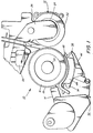
- the detailed structure of the fusing apparatus employed in the fusing station will be described hereinafter with reference to Figures 1 through 3, inclusive.
- Figure 1 schematically depicts the fusing apparatus of the present invention. It will become evident from the following discussion that this fusing apparatus is equally well suited for use in a wide variety of printing machines, and is not necessarily limited in its application to the particular embodiment depicted.
- the fusing apparatus includes a heated fuser roll, indicated generally by the reference numeral 10, and a backup roller, indicated generally by the reference numeral 12.
- a temperature sensor 14 contacts the exterior circumstantial surface of fuser roller 10.
- temperature sensor 14 is a thermistor wherein the resistance thereof varies as a function of the detected temperature.
- the output signal from temperature sensor 14 is a voltage.
- Fuser roller 10 is composed of a hollow tube 16 having a thin covering 18 thereon.
- a heat source 20 is disposed interiorly of tube 16.
- Tube 16 is made from a metal material having the desired heat conductivity characteristics. By way of example, aluminum, copper and other metals having a high thermal conductivity are suitable for use as a tube.
- covering layer 18 is made from silicone rubber.
- Heating element 20 is preferably a halogen lamp. Lamp 20 is connected to sensor 14through a controller.
- Backup roller 12 has a relatively thick layer of silicone rubber 22 on metal tube 24. Backup roller 12 is mounted rotatably on bracket 26. Bracket 26 is actuated by a controller to pivot so as to press backup roller 12 into contact with fuser roller 10 to define a nip therebetween through which the copy sheet passes.
- Switch 28 detects the presence or absence of the copy sheet in the fusing apparatus and indicates the status thereof to the controller. Rollers 10 and 12 remain spaced from each other whenever fusing is not occurring. When fusing is occurring, roller 12 pivots so as to press against fuser roller 10.
- Back up roller 12 and fuser roller 10 are adapted to rotate during the fusing operation so as to advance the copy sheet therethrough.
- Heat source 20 which may be a halogen lamp, or infared lamp, amongst others, is located internally of fuser roller 10.
- a lubricating assembly indicated generally by the reference numeral 32, applies a thin film of silicone oil to silicone layer 18 of fuser roll 10 to prevent offsetting of toner particles thereto.
- Lubricating assembly 32 includes a fluid applicator wick, indicated generally by the reference numeral 34, having a portion thereof in oil reservoir 36 for receiving silicone oil therefrom.
- Fluid applicator wick 34 includes a covered material 46 contacting a fluid retaining material 48.
- the covering material has one surface thereof engaging fuser roll 10 and is adapted to meter silicone oil thereon.
- the covering material of the fluid applicator wick has low friction and good wear properties with little tendency to accumulate molten toner, as well as thermal stability at elevated temperatures.
- Frame 44 holds both fluid retaining material 48 and covering material 46 of fluid applicator wick 34 in their operative positions.
- covering material 46 is exposed to dirt, accumulation, and wear, it is designed to be a replaceable component. It has been found that a limiting factor in the life of the covering material is the degradation and wear that occurs from contact with the rotating fuser roll. As the covering material wears, fibers are pulled from the surface thereof accumulating on the backup roller and downstream copy sheets.
- this wear of the covering material can result in an accumulation of a fluff of material extending from the surface thereof and sometimes protruding into the entrance path of the copy sheet. To extend the life of the covering material, it is necessary to eliminate these wear problems.
- Fluid applicating wick 34 has covering material 46 contacting fluid retaining material 48.
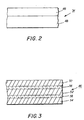
- Covering material 46 is a composite material and will be described hereinafter, in greater detail, with reference to Figure 3.
- fluid retaining material 48 may be made from polyester, Teflon, or Nomex. Teflon and Nomex are trademarks of E. I. Dupont-w de Nemours and Company of Wilmlngton, Delaware.
- Nomex is an aramid, i.e. a highly aromatic polyamide fiber, such as a copolymer of meta- phenylenediamine and isophaloyd chloride.
- any other suitable material may be employed which retains oil therein in the desired amount.
- Covering material 46 includes three relatively thick layers of fiber batts 50, 52, and 54 with a thin, loosely woven gauze-like cloth 56 and 58 interposed between each layer of fiber batts. Thin loosely woven cloth 56 and 58 is known as a scrim. Fiber batt layer 50 and fiber batt layer 52 have a thin gauze-like layer of loosely woven cloth 56 interposed therebetween. Similarly, fiber batt layer 52 and fiber batt layer 54 have a thin gauze-like layer of loosely woven cloth 58 interposed therebetween. After each of the layers are assembled in juxtaposition with one another, the entire covering material is needle punched.
- the fibers of the layers of fiber batts are interlocked with the fibers of the loosely woven layer of cloth interposed therebetween.
- a typical prior art needling apparatus is disclosed in U.S. Patent Number 3,112,552 issued to Smith II on December 3, 1963.
- the needling apparatus described therein includes a plurality of barbed needles which are adapted to penetrate the composite covering material and then be withdrawn therefrom.
- the barbed needles are designed to alternately lift and press the fibers between the layers so as to entangle them with one another.
- the barbed needles cause the fibers of fiber batt layers 50 and 52 to be interlocked with the thin, loosely woven cloth layer 56 interposed therebetween.
- the needling operation also causes the fibers of fiber batts 52 and 54 to be interlocked with loosely woven cloth 58 interposed therebetween.
- Fiber batt layers 50, 52 and 54 may be made from any suitable synthetic materials including a polyester, Teflon, i.e. polytetrafluorethylene, Nomex or natural fibres, such as wool, or any other fiber or blends thereof which are suitable for metering silicone oil.
- the scrim i.e.
- the loosely woven gauze-like layers of cloth 56 and 58 interposed between fiber batts 50 and 52, and 52 and 54, respectively, may also be made from any suitable synthetic fibers including polyester, Teflon, i.e. polytetrafluorethylene, or Nomex or natural fibers, such as wool, or any other fibers or blends thereof. It has been found that the covering material of the present invention meters precise quantities of silicone oil from the fluid retaining material to the fuser roll while having significantly improved wear resistance and extended life. A covering material, having the layers of fiber batts and the thin loosely woven cloth layers interposed therebetween made from Nomex, is believed to have a life of approximately two times that of the conventional covering material, i.e. of about 250,000 copies when used in an electrophotographic printing machine.
- the improved covering material has a plurality of layers of fiber batts with a thin, loosely woven gauze-like cloth layer interposed between the layers of fiber batts with the fibers of the fiber batt layers being interlocked with the thin loosely woven cloth interposed therebetween by a needling process.
- a covering material made In the foregoing manner has significantly reduced wear than covering materials hereinbefore employed.
Landscapes
- Physics & Mathematics (AREA)
- General Physics & Mathematics (AREA)
- Fixing For Electrophotography (AREA)
- Coating Apparatus (AREA)
Claims (10)
charactérisé en ce que le matériau de couverture e e comprend au moins une première couche (50) de fibres et une seconde couche (52) de fibres avec une fine couche (56) au tissage peu serré d'une gaze interposée entre la première couche de fibres et la seconde couche de fibres, avec au moins une partie des fibres de la première couche de fibres et de la seconde couche de fibres entremêlée avec la couche de gaze interposée entre elles.
Applications Claiming Priority (2)
| Application Number | Priority Date | Filing Date | Title |
|---|---|---|---|
| US61311984A | 1984-05-23 | 1984-05-23 | |
| US613119 | 1984-05-23 |
Publications (2)
| Publication Number | Publication Date |
|---|---|
| EP0165719A1 EP0165719A1 (fr) | 1985-12-27 |
| EP0165719B1 true EP0165719B1 (fr) | 1990-05-09 |
Family
ID=24455944
Family Applications (1)
| Application Number | Title | Priority Date | Filing Date |
|---|---|---|---|
| EP19850303619 Expired - Lifetime EP0165719B1 (fr) | 1984-05-23 | 1985-05-22 | Tampon pour applicateur de liquide |
Country Status (4)
| Country | Link |
|---|---|
| EP (1) | EP0165719B1 (fr) |
| JP (1) | JPH0623908B2 (fr) |
| CA (1) | CA1240832A (fr) |
| DE (1) | DE3577606D1 (fr) |
Families Citing this family (9)
| Publication number | Priority date | Publication date | Assignee | Title |
|---|---|---|---|---|
| ATE32273T1 (de) * | 1984-03-07 | 1988-02-15 | Junkosha Co Ltd | Rollenfixiervorrichtung. |
| JPH0673051B2 (ja) * | 1986-02-03 | 1994-09-14 | ジヤパンゴアテツクス株式会社 | 複写機用オイル塗布機構 |
| US4743943A (en) * | 1987-01-12 | 1988-05-10 | International Business Machines Corporation | Renewable fuser wick |
| EP0493652B1 (fr) * | 1990-12-29 | 1995-11-29 | Mitsubishi Materials Corporation | Matériau pour rouleau de nettoyage et appareil de fixage |
| US5327203A (en) * | 1993-01-04 | 1994-07-05 | Xerox Corporation | Web release agent system for a heat and pressure fuser |
| GB9400934D0 (en) * | 1994-01-19 | 1994-03-16 | Gore W L & Ass Uk | Layered oil transfer component |
| US5798181A (en) * | 1994-10-04 | 1998-08-25 | W. L. Gore & Associates, Inc. | Fluoropolymer coated elastomeric rollers and structures |
| US5800908A (en) * | 1995-06-07 | 1998-09-01 | W. L. Gore & Associates, Inc. | Oil delivery sheet material for use in various printer devices |
| JP2014186303A (ja) * | 2013-02-25 | 2014-10-02 | Ricoh Co Ltd | 定着装置および画像形成装置 |
Family Cites Families (8)
| Publication number | Priority date | Publication date | Assignee | Title |
|---|---|---|---|---|
| US3745972A (en) | 1971-07-20 | 1973-07-17 | Xerox Corp | Wicking apparatus |
| US4083322A (en) | 1976-04-09 | 1978-04-11 | Xerox Corporation | Fuser wick |
| US4309957A (en) | 1977-01-03 | 1982-01-12 | Xerox Corporation | Wick for dispensing fuser oil |
| US4336766A (en) | 1980-11-24 | 1982-06-29 | Xerox Corporation | Roll fusing apparatus for electrophotography and release agent management system therefor |
| US4407219A (en) | 1981-07-14 | 1983-10-04 | Schlegel Corporation | Pile brush for conditioning a moving surface |
| JPS5847866U (ja) * | 1981-09-26 | 1983-03-31 | ミノルタ株式会社 | オフセツト防止液供給塗布部材 |
| JPS5930158U (ja) * | 1982-08-17 | 1984-02-24 | 日東電工株式会社 | 定着装置におけるオフセツト防止液供給部材 |
| JPS58111963A (ja) * | 1982-12-23 | 1983-07-04 | Canon Inc | 定着装置 |
-
1985
- 1985-04-18 CA CA000479524A patent/CA1240832A/fr not_active Expired
- 1985-05-13 JP JP60101185A patent/JPH0623908B2/ja not_active Expired - Lifetime
- 1985-05-22 DE DE8585303619T patent/DE3577606D1/de not_active Expired - Fee Related
- 1985-05-22 EP EP19850303619 patent/EP0165719B1/fr not_active Expired - Lifetime
Also Published As
| Publication number | Publication date |
|---|---|
| DE3577606D1 (de) | 1990-06-13 |
| JPS60252382A (ja) | 1985-12-13 |
| CA1240832A (fr) | 1988-08-23 |
| JPH0623908B2 (ja) | 1994-03-30 |
| EP0165719A1 (fr) | 1985-12-27 |
Similar Documents
| Publication | Publication Date | Title |
|---|---|---|
| CA1114885A (fr) | Meche dispensatrice d'huile de fusion | |
| US3718116A (en) | Oil dispensing apparatus | |
| EP0929016B1 (fr) | Appareil de fixage par fusion | |
| US5045890A (en) | Fuser apparatus with release agent delivery system | |
| US4751548A (en) | Apparatus including a conductive wick for applying liquid release agent material to a heated fuser roll | |
| JPH02287580A (ja) | 剥離剤塗布装置 | |
| US5200786A (en) | Donor brush ram system | |
| EP0165719B1 (fr) | Tampon pour applicateur de liquide | |
| US5267004A (en) | Rotating wick for fusing apparatus having improved oil laydown | |
| US5327203A (en) | Web release agent system for a heat and pressure fuser | |
| EP0634708B1 (fr) | Système d'alimentation en agent séparateur | |
| AU670267B2 (en) | Oil reservoir | |
| US3841827A (en) | Toner release oil transfer pad | |
| US6449455B1 (en) | Release agent delivery system for use in printer devices | |
| US5839041A (en) | RAM system including a bidirectional metering member and a dual purpose swiper blade | |
| US5576821A (en) | Fuser release agent management (RAM) system having a non-continuous pattern agent roll | |
| CA1065957A (fr) | Systeme d'application d'un agent de decollage sur un rouleau de fusion chauffant | |
| MXPA96005917A (en) | System for administration of fuser detachment agent that has a roller deagent with patron no conti | |
| GB2433471A (en) | Cleaning system for a fuser apparatus | |
| EP0532235A2 (fr) | Rouleau donneur préchauffé pour la distribution d'huile, pressé par un ressort | |
| US5597413A (en) | Donor brush | |
| US3884181A (en) | Capillary baffle-constant oil height independent of oil level | |
| US5875381A (en) | Release agent applied to fuser roll via paper | |
| JPH11249473A (ja) | 加熱加圧融着構造 | |
| US5493375A (en) | Oil control blade |
Legal Events
| Date | Code | Title | Description |
|---|---|---|---|
| PUAI | Public reference made under article 153(3) epc to a published international application that has entered the european phase |
Free format text: ORIGINAL CODE: 0009012 |
|
| AK | Designated contracting states |
Designated state(s): DE FR GB |
|
| 17P | Request for examination filed |
Effective date: 19860429 |
|
| 17Q | First examination report despatched |
Effective date: 19871127 |
|
| GRAA | (expected) grant |
Free format text: ORIGINAL CODE: 0009210 |
|
| AK | Designated contracting states |
Kind code of ref document: B1 Designated state(s): DE FR GB |
|
| REF | Corresponds to: |
Ref document number: 3577606 Country of ref document: DE Date of ref document: 19900613 |
|
| ET | Fr: translation filed | ||
| PLBE | No opposition filed within time limit |
Free format text: ORIGINAL CODE: 0009261 |
|
| STAA | Information on the status of an ep patent application or granted ep patent |
Free format text: STATUS: NO OPPOSITION FILED WITHIN TIME LIMIT |
|
| 26N | No opposition filed | ||
| PGFP | Annual fee paid to national office [announced via postgrant information from national office to epo] |
Ref country code: FR Payment date: 19930222 Year of fee payment: 9 |
|
| PG25 | Lapsed in a contracting state [announced via postgrant information from national office to epo] |
Ref country code: FR Effective date: 19950131 |
|
| REG | Reference to a national code |
Ref country code: FR Ref legal event code: ST |
|
| PGFP | Annual fee paid to national office [announced via postgrant information from national office to epo] |
Ref country code: GB Payment date: 20000517 Year of fee payment: 16 |
|
| PGFP | Annual fee paid to national office [announced via postgrant information from national office to epo] |
Ref country code: DE Payment date: 20000522 Year of fee payment: 16 |
|
| PG25 | Lapsed in a contracting state [announced via postgrant information from national office to epo] |
Ref country code: GB Free format text: LAPSE BECAUSE OF NON-PAYMENT OF DUE FEES Effective date: 20010522 |
|
| GBPC | Gb: european patent ceased through non-payment of renewal fee |
Effective date: 20010522 |
|
| PG25 | Lapsed in a contracting state [announced via postgrant information from national office to epo] |
Ref country code: DE Free format text: LAPSE BECAUSE OF NON-PAYMENT OF DUE FEES Effective date: 20020301 |