EP0165727B1 - Rotationseinrichtung für Katheter - Google Patents
Rotationseinrichtung für Katheter Download PDFInfo
- Publication number
- EP0165727B1 EP0165727B1 EP85303732A EP85303732A EP0165727B1 EP 0165727 B1 EP0165727 B1 EP 0165727B1 EP 85303732 A EP85303732 A EP 85303732A EP 85303732 A EP85303732 A EP 85303732A EP 0165727 B1 EP0165727 B1 EP 0165727B1
- Authority
- EP
- European Patent Office
- Prior art keywords
- rotary
- limit
- members
- catheter
- assembly
- Prior art date
- Legal status (The legal status is an assumption and is not a legal conclusion. Google has not performed a legal analysis and makes no representation as to the accuracy of the status listed.)
- Expired
Links
- 238000007789 sealing Methods 0.000 claims description 9
- 238000006073 displacement reaction Methods 0.000 claims description 5
- 230000010339 dilation Effects 0.000 claims description 2
- 230000002401 inhibitory effect Effects 0.000 claims description 2
- 210000003813 thumb Anatomy 0.000 description 27
- 210000003414 extremity Anatomy 0.000 description 19
- 210000003141 lower extremity Anatomy 0.000 description 6
- 238000010276 construction Methods 0.000 description 5
- 210000003811 finger Anatomy 0.000 description 4
- 239000004593 Epoxy Substances 0.000 description 3
- 239000000463 material Substances 0.000 description 3
- 229920003023 plastic Polymers 0.000 description 3
- 239000004033 plastic Substances 0.000 description 3
- 230000000712 assembly Effects 0.000 description 2
- 238000000429 assembly Methods 0.000 description 2
- FAPWRFPIFSIZLT-UHFFFAOYSA-M Sodium chloride Chemical compound [Na+].[Cl-] FAPWRFPIFSIZLT-UHFFFAOYSA-M 0.000 description 1
- 239000007788 liquid Substances 0.000 description 1
- 238000004519 manufacturing process Methods 0.000 description 1
- 229910001220 stainless steel Inorganic materials 0.000 description 1
- 239000010935 stainless steel Substances 0.000 description 1
Images
Classifications
-
- A—HUMAN NECESSITIES
- A61—MEDICAL OR VETERINARY SCIENCE; HYGIENE
- A61M—DEVICES FOR INTRODUCING MEDIA INTO, OR ONTO, THE BODY; DEVICES FOR TRANSDUCING BODY MEDIA OR FOR TAKING MEDIA FROM THE BODY; DEVICES FOR PRODUCING OR ENDING SLEEP OR STUPOR
- A61M25/00—Catheters; Hollow probes
- A61M25/01—Introducing, guiding, advancing, emplacing or holding catheters
Definitions
- This invention relates to a catheter rotary assembly comprising a rotary member and a fitting for attachment to an adapter of a steerable balloon-type dilatation catheter having a flexible core wire extending through the adapter and for extending through the fitting.
- Patent Specification US-A-4 362 150 discloses a catheter rotary assembly which comprises a rotary member and a fitting for attachment to an adapter of a steerable balloon-type dilation catheter having a flexible core wire extending through the adapter and for extending through the fitting, the rotary member being secured to the fitting for connection to the core wire, the assembly including means which is disposed within the fitting for sealing between the core wire and the fitting and means limiting the displacement of the rotary member relative to the fitting upon rotation of the rotary member.
- the rotary member is a sleeve which is closed at one end, the flexible core wire or tube being connected to the closed end.
- the fitting is fixed to the adapter and extends through the open end of the rotary member.
- the fitting has an external screw-thread and the rotary member has an internal screw-thread co-operating with the screw-thread of the fitting.
- the rotary member and the fitting have abutment surfaces provided internally of the rotary member to limit rotation of the rotary member relative to the fitting.
- the sealing means comprises two O-rings.
- the present invention is characterised in that the fitting has a screw-thread bore in which the sealing means is disposed, in that a second rotary member is provided which has a screw-threaded projection which extends into the bore of the fitting and engages the sealing means, and in that the first said rotary member has a screw-threaded projection which extends into a screw-threaded bore in the second rotary member, the means limiting relative displacement of the first rotary member being carried by one of the rotary members.
- the present invention provides an assembly which allows a desired amount of displacement of the first rotary member to be chosen.
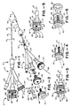
- Figures 1 and 2 show a rotation limiter device 11 which is part of a low-profile steerable balloon-type dilatation catheter 12.
- the catheter 12 comprises a flexible core or guide wire 13 formed of a suitable material such as stainless steel. It typically has a length of 150 centimeters for a conventional catheter or approximately 40 centimetres for an intraoperative catheter.
- the core wire 13 is preferably circular in cross-section and has a diameter which is greater than 0.013 inches (0.23 mm).
- the distal extremity of the core wire can be necked down at the distal extremity to provide greater flexibility at the distal extremity of the core wire.
- a balloon 16 is carried by the distal extremity of the tubular member 14 and preferably is formed integral with the tubular member 14.
- the tubular member 14 provides an annular flow passage or lumen 17 in conjunction with the core wire 13 which extends the length of the core wire from the proximal end to the distal end of the tubular member 14 to establish communication with the balloon 16.
- the distal extremity of the balloon 16 is bonded to the distal extremity of the core wire 13 to form a liquid-tight seal therebetween.
- a flexible tip 18 is formed on the distal extremity of the core wire 13.
- a triple arm adapter 21 is secured to the proximal extremity of the tubular member 14. It is provided with a first or central arm 22 and second and third side arms 23 and 24.
- the adapter 21 is provided with a fitting 26 which has a threaded exterior with a conical distal extremity 27 over which the proximal extremity of the tubular member 14 is adapted to fit.
- An interiorly threaded cylindrical member 28 is provided for retaining the proximal extremity of the tubular member 14 on the conical portion 27 and is threaded onto the fitting 26.
- the central arm 22 carries an interiorly threaded fitting 31 which is generally conical in shape and is adapted to receive sealing means in the form of an 0-ring 32.
- a rotary member or thumb-screw 33 is provided for engaging the 0- ring 32 and clamping it into sealing engagement with the core wire 13 which extends through the central arm 22 through the fitting 31 through the 0-ring 32 and through the thumb screw 33.
- the thumb screw 33 consists of a knurled knob 34 and carries an exteriorly threaded axially extending extension or member 36 which is adapted to be threaded into the fitting 31 and engage the O-ring 32.
- a rotary member or torque knob 38 is provided for imparting rotational movement to the core wire 13 and consists of a knurled knob 39 which has an exteriorally threaded axially extending extension or member 41 carried thereby which is adapted to be threaded into an interiorly threaded bore 42 provided in the thumb screw 33.
- the core wire 13 extends through the torque knob 38 and is secured thereto in a suitable manner such as by the use of plastics 43 and a set screw 44 threaded into the knob and engaging the core wire 13 so that the core wire 13 will be rotated by the torque knob.
- a stop member 46 which is generally in the form of an elongate cylinder, is provided with an elongate cutout 47 extending longitudinally of the stop member.
- the cutout 47 provides spaced apart parallel lips 48 and 49.
- the stop member 46 is also provided with an elongate slot 51 which opens through qhe cutout 47.
- the slot 51 is adapted to receive a screw 52.
- the screw 52 extends through the slot and is adapted to secure the stop member 46 to one of the knobs carried either by the thumb screw 33 or by the torque knob 38.
- the stop member 46 is secured to the knob 39 in such a manner that the lips 48 and 49 underlie the knob 34 and overlie the knob 39 for a purpose hereinafter described.
- the stop member is provided with a conical upper end 53 which is readily adapted to be engaged by a finger of the human hand.
- the second arm 23 also carries a fitting 56 similar to the fitting 31 carried by the central arm 22 and is provided with an 0-ring (not shown) which is adapted to be engaged by a thumb screw 57.
- a bleed or vent wire 58 extends through the thumb screw 57 and through the arm 23 into the lumen provided by the tubular member 14 and into the distal extremity of the balloon 16.
- the other arm 24 is adapted to receive a syringe or other suitable inflating device for introducing a saline solution or radiocontrast liquid into the lumen leading to the balloon 16 to inflate the balloon and to cause any air therein to be expelled through the bleed wire 58. Operation of the catheter rotary assembly will now be briefly described as follows.
- the stop member 46 can be fixed in position on the knob 39 by tightening the screw 52.
- the screw 52 can be provided with special means as, for example, a Phillips head or an Allen head to discourage tampering with the positioning of the stop member 46 away from the factory after assembly.
- the stop member 46 rather than mounting the stop member 46 on the knob 39, the stop member alternatively can be mounted on the knob 34 in which case the spacing between the lip 49 and the upper surface of the knob 39 would control the number of revolutions for the torque knob 38.
- FIG. 3 Another cathether rotary assembly including a rotation limiter device 59 is shown in Figures 3 and 4.
- the assembly comprises a rotary member or thumb screw 61 which is threaded into the fitting 31.
- the thumb screw 61 is similar to the thumb screw 33 hereinbefore described with the exception that it is provided with a bevel 62 for the purpose hereinafter described.
- a rotary member or torque knob 66 comprises of a knob 67 which carries an externally threaded axially extending extension member 68.
- the torque knob 66 can be formed of a suitable material such as plastic and is provided with first and second diametrically opposed legs or arms 69 which extend in a direction parallel to the member 68.
- the distal extremities of the arms 69 are provided with inwardly extending abutments or lips 71 which are formed integral therewith and which are spaced a predetermined distance from the innermost surface of the knob 67.
- An upstanding protrusion 72 is formed on the knob 67 and is offset to one side thereof and extends outwardly from the outer extremity of the knob 67.
- the protrusion 72 is adapted to be engaged by a finger of a hand.
- the guide wire 13 hereinbefore described extends through the torque knob 66 and is secured thereto by an epoxy 43 as well as by a set screw 74.
- the torque knob 66 has its member 68 threaded into the thumb screw 61 in such a manner so that the lowermost curved extremities of the abutments or lips 71 engage the chamfer 62 on the thumb screw 61.
- the chamfer 62 urges the lower extremities of the arms 69 outwardly as continued rotation of the torque knob 66 moves the legs or arms 69 downwardly until the abutments or lips 71 clear the side margins of the thumb screw and thereafter snap over the lower extremities of the thumb screw 61.
- the torque knob 66 can continue to be rotated until the lower surface of the knob 67 engages the upper surface of the thumb screw 61. Also, it can be seen that the amount of rotation of the torque knob 67 is limited by the arms 69, with the number of rotations of the torque knob 66 being controlled by the full length of the arms 69. As soon as the lips or abutments 71 engage the lower surface of the thumb screw 61, further rotation will be prevented.
- rotation of a torque knob 66 can be limited to a predetermined amount as, for example, one turn, two turns, or three turns, as the case may be.
- the rotation limiter device 59 in addition to being relatively simple prevents canting of the torque knob 66 because the arms or legs 69 are provided on diametrically opposite sides of the threaded arm member 68.
- the torque knob 66 can be readily rotated by a finger engaging the cylindrical protrusion 72.
- FIG. 5 Still another catheter rotary assembly including a rotation limiter device 76 is shown in Figures 5 and 6.
- a rotary member or thumb screw 77 is threaded into the fitting 31.
- the thumb screw 77 is similar to the thumb screw 61 hereinbefore described with the exception that it is not provided with a chamfer.
- the thumb screw 77 is provided with a cylindrical unknurled portion 78.
- a rotary member or torque knob 79 includes a cylindrical knob 81 which carries an external axially extending threaded extension member 82.
- the torque knob 79 is provided with first and second diametrically opposed legs or arms 83 which extend in a direction parallel to the extension member 82.
- Means is carried by the distal extremities of the legs or arms 83 to stiffen the legs or arms and to prevent the legs or arms 83 from being cammed outwardly and consists of a ring 84 which has its outer circumference bonded to the distal extremities of the leg 83 by suitable means such as an expoxy.
- the ring 84 is provided with upper and lower annular surfaces 86.
- the upper surface 86 is adapted to engage and seat against the lower surface of the thumb screw 77 as hereinafter described.
- a protrusion 88 is carried by the torque knob 79 and is adapted to be engaged by the finger of a hand to facilitate rotation of the torque knob 79.
- the guide wire 13 hereinbefore described extends through the torque knob 79 and is secured thereto by a body 89 of a suitable epoxy as well as by a set screw 91.
- the assembly is the same as hereinbefore described with respect to the previous constructions except that the ring 84 is bonded to the distal extremities of the legs 83 after the legs 83 have been passed over the torque knob 79. As soon as this has been accomplished, the circumferential portions of the ring 84 can be bonded to the distal extremities of the legs 83 by suitable means such as an epoxy.
- the torque knob 79 can be rotated in counterclockwise direction so that the torque knob 79 moves away from with respect to the thumb screw 77. This can continue until the top surface 86 of the annular ring 84 comes into engagement with the lower surface of the thumb screw 77 inhibiting further rotation.
- the length of the legs and the relationship with the threads on the extension member 82 can be selected so that a predetermined number of turns as, for example, a maximum of three turns are permitted. This helps to ensure that there will not be over rotation of the balloon carried by the catheter.
- annular ring 84 is particularly advantageous in that it prohibits any inadvertent possible snapping outwardly of the legs 83 and thus provides assurance that the rotation of the guide wire 18 cannot exceed a total of three revolutions. It should be appreciated that if desired, the legs or arms 83 can be made shorter or longer with respect to the threads on the extension member 82 to provide the desired number of revolutions. This makes it possible to precisely control the rotation so that the balloon carried by the end of the catheter will not be unduly twisted.
Landscapes
- Health & Medical Sciences (AREA)
- Life Sciences & Earth Sciences (AREA)
- Biophysics (AREA)
- Pulmonology (AREA)
- Engineering & Computer Science (AREA)
- Anesthesiology (AREA)
- Biomedical Technology (AREA)
- Heart & Thoracic Surgery (AREA)
- Hematology (AREA)
- Animal Behavior & Ethology (AREA)
- General Health & Medical Sciences (AREA)
- Public Health (AREA)
- Veterinary Medicine (AREA)
- Media Introduction/Drainage Providing Device (AREA)
Claims (9)
Applications Claiming Priority (4)
| Application Number | Priority Date | Filing Date | Title |
|---|---|---|---|
| US615139 | 1975-09-19 | ||
| US61513984A | 1984-05-30 | 1984-05-30 | |
| US06/732,641 US4619263A (en) | 1984-05-30 | 1985-05-10 | Adjustable rotation limiter device for steerable dilatation catheters |
| US732641 | 1985-05-10 |
Publications (2)
| Publication Number | Publication Date |
|---|---|
| EP0165727A1 EP0165727A1 (de) | 1985-12-27 |
| EP0165727B1 true EP0165727B1 (de) | 1988-07-13 |
Family
ID=27087429
Family Applications (1)
| Application Number | Title | Priority Date | Filing Date |
|---|---|---|---|
| EP85303732A Expired EP0165727B1 (de) | 1984-05-30 | 1985-05-28 | Rotationseinrichtung für Katheter |
Country Status (4)
| Country | Link |
|---|---|
| US (1) | US4619263A (de) |
| EP (1) | EP0165727B1 (de) |
| CA (1) | CA1238544A (de) |
| DE (1) | DE3563687D1 (de) |
Families Citing this family (89)
| Publication number | Priority date | Publication date | Assignee | Title |
|---|---|---|---|---|
| US4664113A (en) * | 1984-05-30 | 1987-05-12 | Advanced Cardiovascular Systems, Inc. | Steerable dilatation catheter with rotation limiting device |
| US5114414A (en) * | 1984-09-18 | 1992-05-19 | Medtronic, Inc. | Low profile steerable catheter |
| US4960411A (en) * | 1984-09-18 | 1990-10-02 | Medtronic Versaflex, Inc. | Low profile sterrable soft-tip catheter |
| US4944740A (en) * | 1984-09-18 | 1990-07-31 | Medtronic Versaflex, Inc. | Outer exchange catheter system |
| US4641654A (en) * | 1985-07-30 | 1987-02-10 | Advanced Cardiovascular Systems, Inc. | Steerable balloon dilatation catheter assembly having dye injection and pressure measurement capabilities |
| US5061273A (en) * | 1989-06-01 | 1991-10-29 | Yock Paul G | Angioplasty apparatus facilitating rapid exchanges |
| US5350395A (en) * | 1986-04-15 | 1994-09-27 | Yock Paul G | Angioplasty apparatus facilitating rapid exchanges |
| US4723936A (en) * | 1986-07-22 | 1988-02-09 | Versaflex Delivery Systems Inc. | Steerable catheter |
| US5125895A (en) * | 1986-07-22 | 1992-06-30 | Medtronic Versaflex, Inc. | Steerable catheter |
| US4846174A (en) * | 1986-08-08 | 1989-07-11 | Scimed Life Systems, Inc. | Angioplasty dilating guide wire |
| US4976720A (en) * | 1987-01-06 | 1990-12-11 | Advanced Cardiovascular Systems, Inc. | Vascular catheters |
| US4793350A (en) * | 1987-01-06 | 1988-12-27 | Advanced Cardiovascular Systems, Inc. | Liquid filled low profile dilatation catheter |
| US4838859A (en) * | 1987-05-19 | 1989-06-13 | Steve Strassmann | Steerable catheter |
| US4844092A (en) * | 1988-03-28 | 1989-07-04 | Schneider-Shiley (Usa) Inc. | Catheter Y-connector with guidewire locking means |
| US5055109A (en) * | 1989-10-05 | 1991-10-08 | Advanced Cardiovascular Systems, Inc. | Torque transmitting assembly for intravascular devices |
| US5345945A (en) * | 1990-08-29 | 1994-09-13 | Baxter International Inc. | Dual coil guidewire with radiopaque distal tip |
| EP0476807A1 (de) * | 1990-09-17 | 1992-03-25 | C.R. Bard, Inc. | Lenkbare Katheter mit Kerndraht |
| EP0555412B1 (de) * | 1990-10-31 | 1997-01-08 | BAXTER INTERNATIONAL INC. (a Delaware corporation) | Katheter mit führungsdraht |
| US5163911A (en) * | 1990-10-31 | 1992-11-17 | Baxter International Inc. | Over-the-wire catheter |
| US5185004A (en) * | 1991-06-03 | 1993-02-09 | Danforth Biomedical, Inc. | Turn-limiting proximal adaptor for steerable catheter systems |
| US5205822A (en) * | 1991-06-10 | 1993-04-27 | Cordis Corporation | Replaceable dilatation catheter |
| EP0592720B1 (de) * | 1991-06-10 | 1998-07-29 | Cordis Corporation | Auswechselbarer Dilatationskatheter |
| CA2074304C (en) * | 1991-08-02 | 1996-11-26 | Cyril J. Schweich, Jr. | Drug delivery catheter |
| US5327905A (en) * | 1992-02-14 | 1994-07-12 | Boaz Avitall | Biplanar deflectable catheter for arrhythmogenic tissue ablation |
| US5352197A (en) * | 1992-03-18 | 1994-10-04 | The Spectranetics Corporation | Turn limiter for a catheter with twistable tip |
| EP0587859A4 (de) * | 1992-03-18 | 1995-02-22 | Spectranetics Corp | Optische fasern aufweisender katheter mit drehbarem endstück. |
| US5290230A (en) * | 1992-05-11 | 1994-03-01 | Advanced Cardiovascular Systems, Inc. | Intraluminal catheter with a composite shaft |
| US5287857A (en) * | 1992-06-22 | 1994-02-22 | David Mann | Apparatus and method for obtaining an arterial biopsy |
| US5456680A (en) * | 1993-09-14 | 1995-10-10 | Spectranetics Corp | Fiber optic catheter with shortened guide wire lumen |
| US5624379A (en) * | 1995-10-13 | 1997-04-29 | G. I. Medical Technologies, Inc. | Endoscopic probe with discrete rotatable tip |
| US5830183A (en) * | 1997-06-30 | 1998-11-03 | Schneider (Usa) Inc | Clip device for vascular catheter |
| US20070225615A1 (en) * | 2006-03-22 | 2007-09-27 | Revascular Therapeutics Inc. | Guidewire controller system |
| US6059767A (en) * | 1998-02-25 | 2000-05-09 | Norborn Medical, Inc. | Steerable unitary infusion catheter/guide wire incorporating detachable infusion port assembly |
| US20050119615A1 (en) * | 2000-04-06 | 2005-06-02 | Norborn Medical, Inc. | Guidewire for crossing occlusions or stenoses |
| US9254143B2 (en) | 1998-02-25 | 2016-02-09 | Revascular Therapeutics, Inc. | Guidewire for crossing occlusions or stenoses having a shapeable distal end |
| US6824550B1 (en) * | 2000-04-06 | 2004-11-30 | Norbon Medical, Inc. | Guidewire for crossing occlusions or stenosis |
| US6746422B1 (en) | 2000-08-23 | 2004-06-08 | Norborn Medical, Inc. | Steerable support system with external ribs/slots that taper |
| US20080140101A1 (en) * | 2006-12-07 | 2008-06-12 | Revascular Therapeutic, Inc. | Apparatus for crossing occlusions or stenoses |
| US6780199B2 (en) | 1998-05-15 | 2004-08-24 | Advanced Cardiovascular Systems, Inc. | Enhanced stent delivery system |
| US6740104B1 (en) * | 1998-05-15 | 2004-05-25 | Advanced Cardiovascular Systems, Inc. | Enhanced catheter with alignment means |
| CA2330134A1 (en) * | 1998-05-15 | 1999-11-25 | Medgination, Inc. | Enhanced balloon dilatation system |
| US20020007145A1 (en) | 1998-10-23 | 2002-01-17 | Timothy Stivland | Catheter having improved bonding region |
| US7381198B2 (en) | 2000-08-23 | 2008-06-03 | Revascular Therapeutics, Inc. | Steerable distal support system |
| US7071898B2 (en) * | 2002-07-18 | 2006-07-04 | Information Decision Technologies, Llc | Method for using a wireless motorized camera mount for tracking in augmented reality |
| US8591540B2 (en) | 2003-02-27 | 2013-11-26 | Abbott Cardiovascular Systems Inc. | Embolic filtering devices |
| US7582740B2 (en) * | 2003-04-17 | 2009-09-01 | The Trustees Of Columbia University In The City Of New York | Methods and kits for detecting SARS-associated coronavirus |
| US20050209674A1 (en) * | 2003-09-05 | 2005-09-22 | Kutscher Tuvia D | Balloon assembly (V) |
| US20050159728A1 (en) * | 2004-01-15 | 2005-07-21 | Thomas Medical Products, Inc. | Steerable sheath |
| US20060089569A1 (en) * | 2004-10-26 | 2006-04-27 | Soukup Thomas M | Articulator with adjustable stiffness distal portion |
| US20060184105A1 (en) * | 2005-02-15 | 2006-08-17 | Townsend Gregory L | Thin wall catheter and method of placing same |
| US7892186B2 (en) * | 2005-12-09 | 2011-02-22 | Heraeus Materials S.A. | Handle and articulator system and method |
| JP4905647B2 (ja) * | 2006-02-14 | 2012-03-28 | 朝日インテック株式会社 | 医療用具 |
| US7985228B2 (en) * | 2006-08-25 | 2011-07-26 | Kyphon Sarl | Apparatus and methods for use of expandable members in surgical applications |
| US8926620B2 (en) | 2006-08-25 | 2015-01-06 | Kyphon Sarl | Apparatus and methods for use of expandable members in surgical applications |
| US20090131831A1 (en) * | 2007-11-15 | 2009-05-21 | Wright-Ahn Technologies, Llc | Variable Stiffness Guidewire Systems |
| US9510885B2 (en) | 2007-11-16 | 2016-12-06 | Osseon Llc | Steerable and curvable cavity creation system |
| US20090131867A1 (en) | 2007-11-16 | 2009-05-21 | Liu Y King | Steerable vertebroplasty system with cavity creation element |
| US8070694B2 (en) | 2008-07-14 | 2011-12-06 | Medtronic Vascular, Inc. | Fiber based medical devices and aspiration catheters |
| US8657821B2 (en) | 2008-11-14 | 2014-02-25 | Revascular Therapeutics Inc. | Method and system for reversibly controlled drilling of luminal occlusions |
| US8162891B2 (en) | 2008-11-26 | 2012-04-24 | Revascular Therapeutics, Inc. | Delivery and exchange catheter for storing guidewire |
| US20100298832A1 (en) | 2009-05-20 | 2010-11-25 | Osseon Therapeutics, Inc. | Steerable curvable vertebroplasty drill |
| US8702689B2 (en) | 2009-09-01 | 2014-04-22 | Boston Scientific Scimed, Inc. | Systems and methods for twisting an expansion element of a cryoablation system |
| US9125671B2 (en) | 2010-04-29 | 2015-09-08 | Dfine, Inc. | System for use in treatment of vertebral fractures |
| US9326872B2 (en) * | 2010-08-17 | 2016-05-03 | W. L. Gore & Associates, Inc. | Forced deployment sequence handle assembly with independent actuating mechanism |
| JP2014521462A (ja) | 2011-08-05 | 2014-08-28 | シルク・ロード・メディカル・インコーポレイテッド | 急性虚血性脳卒中を治療するための方法及びシステム |
| US10779855B2 (en) | 2011-08-05 | 2020-09-22 | Route 92 Medical, Inc. | Methods and systems for treatment of acute ischemic stroke |
| US8814832B1 (en) * | 2013-02-15 | 2014-08-26 | Ibrahim Rashid Al-Rashdan | Expandable sheath and system for intravascular insertion of a medical implement using the same |
| JP6204085B2 (ja) * | 2013-06-27 | 2017-09-27 | オリンパス株式会社 | 内視鏡用処置具および内視鏡システム |
| US9265512B2 (en) | 2013-12-23 | 2016-02-23 | Silk Road Medical, Inc. | Transcarotid neurovascular catheter |
| US9820761B2 (en) | 2014-03-21 | 2017-11-21 | Route 92 Medical, Inc. | Rapid aspiration thrombectomy system and method |
| US11065019B1 (en) | 2015-02-04 | 2021-07-20 | Route 92 Medical, Inc. | Aspiration catheter systems and methods of use |
| US10426497B2 (en) | 2015-07-24 | 2019-10-01 | Route 92 Medical, Inc. | Anchoring delivery system and methods |
| EP4674460A3 (de) | 2015-02-04 | 2026-03-25 | Route 92 Medical, Inc. | Schnelles aspirationsthrombektomiesystem |
| US10716915B2 (en) | 2015-11-23 | 2020-07-21 | Mivi Neuroscience, Inc. | Catheter systems for applying effective suction in remote vessels and thrombectomy procedures facilitated by catheter systems |
| US11229445B2 (en) | 2016-10-06 | 2022-01-25 | Mivi Neuroscience, Inc. | Hydraulic displacement and removal of thrombus clots, and catheters for performing hydraulic displacement |
| EP3531934B1 (de) | 2016-10-27 | 2024-08-21 | Dfine, Inc. | Artikulierendes osteotom mit zementabgabekanal |
| AU2017363356B2 (en) | 2016-11-28 | 2023-02-09 | Dfine, Inc. | Tumor ablation devices and related methods |
| US10470781B2 (en) | 2016-12-09 | 2019-11-12 | Dfine, Inc. | Medical devices for treating hard tissues and related methods |
| EP3565486B1 (de) | 2017-01-06 | 2021-11-10 | Dfine, Inc. | Osteotom mit distalem abschnitt zum gleichzeitigen vorschieben und artikulieren |
| AU2018208460B2 (en) | 2017-01-10 | 2023-03-16 | Route 92 Medical, Inc. | Aspiration catheter systems and methods of use |
| CN114916978B (zh) | 2017-01-20 | 2025-02-25 | 92号医疗公司 | 单操作者颅内医疗装置输送系统和使用方法 |
| US11234723B2 (en) | 2017-12-20 | 2022-02-01 | Mivi Neuroscience, Inc. | Suction catheter systems for applying effective aspiration in remote vessels, especially cerebral arteries |
| US10478535B2 (en) | 2017-05-24 | 2019-11-19 | Mivi Neuroscience, Inc. | Suction catheter systems for applying effective aspiration in remote vessels, especially cerebral arteries |
| US11294414B2 (en) * | 2018-04-05 | 2022-04-05 | Medos International Sàrl | Surgical instruments with rotation stop devices |
| CN112423824B (zh) | 2018-05-17 | 2023-02-21 | 92号医疗公司 | 抽吸导管系统和使用方法 |
| WO2020097339A1 (en) | 2018-11-08 | 2020-05-14 | Dfine, Inc. | Tumor ablation device and related systems and methods |
| US11986229B2 (en) | 2019-09-18 | 2024-05-21 | Merit Medical Systems, Inc. | Osteotome with inflatable portion and multiwire articulation |
| US11617865B2 (en) | 2020-01-24 | 2023-04-04 | Mivi Neuroscience, Inc. | Suction catheter systems with designs allowing rapid clearing of clots |
| EP4225167A4 (de) | 2020-10-09 | 2024-10-09 | Route 92 Medical, Inc. | Aspirationskathetersysteme und verfahren zur verwendung |
Family Cites Families (8)
| Publication number | Priority date | Publication date | Assignee | Title |
|---|---|---|---|---|
| US3503385A (en) * | 1965-09-27 | 1970-03-31 | Cordis Corp | Guidable catheter assembly and manipulator therefor |
| US3552384A (en) * | 1967-07-03 | 1971-01-05 | American Hospital Supply Corp | Controllable tip guide body and catheter |
| US4292974A (en) * | 1980-01-30 | 1981-10-06 | Thomas J. Fogarty | Dilatation catheter apparatus and method |
| US4362150A (en) * | 1980-09-10 | 1982-12-07 | Kontron Cardiovascular Inc. | Percutaneous intra-aortic balloon apparatus |
| US4338942A (en) * | 1980-10-20 | 1982-07-13 | Fogarty Thomas J | Dilatation catherter apparatus |
| US4403612A (en) * | 1980-10-20 | 1983-09-13 | Fogarty Thomas J | Dilatation method |
| US4332254A (en) * | 1980-11-17 | 1982-06-01 | Advanced Catheter Systems, Inc. | System for filling and inflating and deflating a vascular dilating cathether assembly |
| US4422447A (en) * | 1981-04-13 | 1983-12-27 | Peter Schiff | Percutaneous balloon |
-
1985
- 1985-05-10 US US06/732,641 patent/US4619263A/en not_active Expired - Lifetime
- 1985-05-28 DE DE8585303732T patent/DE3563687D1/de not_active Expired
- 1985-05-28 EP EP85303732A patent/EP0165727B1/de not_active Expired
- 1985-05-29 CA CA000482668A patent/CA1238544A/en not_active Expired
Also Published As
| Publication number | Publication date |
|---|---|
| US4619263A (en) | 1986-10-28 |
| EP0165727A1 (de) | 1985-12-27 |
| CA1238544A (en) | 1988-06-28 |
| DE3563687D1 (en) | 1988-08-18 |
Similar Documents
| Publication | Publication Date | Title |
|---|---|---|
| EP0165727B1 (de) | Rotationseinrichtung für Katheter | |
| US11648383B2 (en) | Medical break-away connectors | |
| US4664113A (en) | Steerable dilatation catheter with rotation limiting device | |
| JP4691528B2 (ja) | 流体流を制御するための調節可能の二方弁構造および限界圧力差を調節する方法 | |
| US4064882A (en) | Tracheostomy tube with pressure relief valve | |
| CA1239316A (en) | Catheter placement device | |
| US5591136A (en) | Injection device | |
| US5117839A (en) | Exchangeable fixed wire catheter | |
| US4210174A (en) | Positive pressure valves | |
| US4147170A (en) | Catheter with inflation control device | |
| WO1986004821A1 (en) | Apparatus for regulating the flow of fluid in medical apparatus | |
| WO1999043377A1 (en) | Steerable unitary infusion catheter/guide wire incorporating detachable infusion port assembly | |
| US11944768B2 (en) | Catheter tip for a catheter assembly | |
| EP0428378A2 (de) | Flexibler Sprühkopf für Spritzen | |
| US3042067A (en) | Tube clamp | |
| EP0607343B1 (de) | Rotierbarer, medizinaler ventilverschluss | |
| US4240430A (en) | Syringe assembly | |
| JPS62501822A (ja) | 医療装置の迅速流量制御装置 | |
| EP0209863A1 (de) | Einstellbares Ventil für Flüssigkeiten für medizinische Ausrüstung | |
| WO1980000307A1 (en) | Tracheal tubes | |
| US5092854A (en) | Two-part flexible swivel spray tip for syringe | |
| US6537266B1 (en) | Puncture guard for catheter wire | |
| CA2105499A1 (en) | Flexible catheter | |
| US20170056624A1 (en) | Mechanism for controlling unintentional movement of components | |
| CA1075116A (en) | Syringe assembly |
Legal Events
| Date | Code | Title | Description |
|---|---|---|---|
| PUAI | Public reference made under article 153(3) epc to a published international application that has entered the european phase |
Free format text: ORIGINAL CODE: 0009012 |
|
| AK | Designated contracting states |
Designated state(s): CH DE FR GB LI |
|
| 17P | Request for examination filed |
Effective date: 19860520 |
|
| 17Q | First examination report despatched |
Effective date: 19870601 |
|
| GRAA | (expected) grant |
Free format text: ORIGINAL CODE: 0009210 |
|
| AK | Designated contracting states |
Kind code of ref document: B1 Designated state(s): CH DE FR GB LI |
|
| REF | Corresponds to: |
Ref document number: 3563687 Country of ref document: DE Date of ref document: 19880818 |
|
| ET | Fr: translation filed | ||
| PLBE | No opposition filed within time limit |
Free format text: ORIGINAL CODE: 0009261 |
|
| STAA | Information on the status of an ep patent application or granted ep patent |
Free format text: STATUS: NO OPPOSITION FILED WITHIN TIME LIMIT |
|
| 26N | No opposition filed | ||
| PGFP | Annual fee paid to national office [announced via postgrant information from national office to epo] |
Ref country code: FR Payment date: 19910314 Year of fee payment: 7 |
|
| PGFP | Annual fee paid to national office [announced via postgrant information from national office to epo] |
Ref country code: GB Payment date: 19910415 Year of fee payment: 7 |
|
| PGFP | Annual fee paid to national office [announced via postgrant information from national office to epo] |
Ref country code: DE Payment date: 19910429 Year of fee payment: 7 |
|
| PGFP | Annual fee paid to national office [announced via postgrant information from national office to epo] |
Ref country code: CH Payment date: 19910614 Year of fee payment: 7 |
|
| PG25 | Lapsed in a contracting state [announced via postgrant information from national office to epo] |
Ref country code: GB Effective date: 19920528 |
|
| PG25 | Lapsed in a contracting state [announced via postgrant information from national office to epo] |
Ref country code: LI Effective date: 19920531 Ref country code: CH Effective date: 19920531 |
|
| GBPC | Gb: european patent ceased through non-payment of renewal fee |
Effective date: 19920528 |
|
| PG25 | Lapsed in a contracting state [announced via postgrant information from national office to epo] |
Ref country code: FR Effective date: 19930129 |
|
| REG | Reference to a national code |
Ref country code: CH Ref legal event code: PL |
|
| PG25 | Lapsed in a contracting state [announced via postgrant information from national office to epo] |
Ref country code: DE Effective date: 19930202 |
|
| REG | Reference to a national code |
Ref country code: FR Ref legal event code: ST |