EP0165760B1 - Dispositif d'isolation acoustique - Google Patents
Dispositif d'isolation acoustique Download PDFInfo
- Publication number
- EP0165760B1 EP0165760B1 EP85304149A EP85304149A EP0165760B1 EP 0165760 B1 EP0165760 B1 EP 0165760B1 EP 85304149 A EP85304149 A EP 85304149A EP 85304149 A EP85304149 A EP 85304149A EP 0165760 B1 EP0165760 B1 EP 0165760B1
- Authority
- EP
- European Patent Office
- Prior art keywords
- sound
- container
- insulating device
- sound insulating
- spaces
- Prior art date
- Legal status (The legal status is an assumption and is not a legal conclusion. Google has not performed a legal analysis and makes no representation as to the accuracy of the status listed.)
- Expired
Links
Images


Classifications
-
- E—FIXED CONSTRUCTIONS
- E04—BUILDING
- E04B—GENERAL BUILDING CONSTRUCTIONS; WALLS, e.g. PARTITIONS; ROOFS; FLOORS; CEILINGS; INSULATION OR OTHER PROTECTION OF BUILDINGS
- E04B1/00—Constructions in general; Structures which are not restricted either to walls, e.g. partitions, or floors or ceilings or roofs
- E04B1/62—Insulation or other protection; Elements or use of specified material therefor
- E04B1/74—Heat, sound or noise insulation, absorption, or reflection; Other building methods affording favourable thermal or acoustical conditions, e.g. accumulating of heat within walls
- E04B1/82—Heat, sound or noise insulation, absorption, or reflection; Other building methods affording favourable thermal or acoustical conditions, e.g. accumulating of heat within walls specifically with respect to sound only
-
- E—FIXED CONSTRUCTIONS
- E04—BUILDING
- E04B—GENERAL BUILDING CONSTRUCTIONS; WALLS, e.g. PARTITIONS; ROOFS; FLOORS; CEILINGS; INSULATION OR OTHER PROTECTION OF BUILDINGS
- E04B1/00—Constructions in general; Structures which are not restricted either to walls, e.g. partitions, or floors or ceilings or roofs
- E04B1/62—Insulation or other protection; Elements or use of specified material therefor
- E04B1/74—Heat, sound or noise insulation, absorption, or reflection; Other building methods affording favourable thermal or acoustical conditions, e.g. accumulating of heat within walls
- E04B1/82—Heat, sound or noise insulation, absorption, or reflection; Other building methods affording favourable thermal or acoustical conditions, e.g. accumulating of heat within walls specifically with respect to sound only
- E04B1/84—Sound-absorbing elements
Definitions
- This invention relates to a sound insulating device to be installed in a communicating port for communicating two spaces separated off from one another and adapted to reduce sound propagation from one space to the other through the communicating port.
- DE-A-1 935 990 discloses a sound damping arrangement in which an annular channel is formed in a duct through which sound energy is propagated by the positioning therein of a parabolic acoustic reflector which focusses the sound waves to a limited region lined with sound absorbing material. This region is offset with respect to the axis of the annular channel.
- the above mentioned conventional sound absorbing measures have such disadvantages as increased resistance to air passage, increase in duct length, increased duct weight and increase in the external dimension thereof.
- a sound insulating device for installation in means inter-communicating two spaces, which spaces are otherwise separated from one another by partition means, to reduce sound propagation between the two spaces while allowing air or gas exchange therebetween, which device comprises a container having first and second openings respectively communicating the interior of the container with the two spaces, sound absorbing means attached to an internal surface of the container and sound converging means for causing a sound wave entering the container from the first space to converge at a predetermined location in the container, said second opening of the container being offset with respect to said predetermined location.
- the sound converging means comprises a plurality of partition plates extending parallel to one another towards the interior of the container from said first opening to define a plurality of parallel passages each defined by a pair of parallel walls, the ends of the partition plates within the container being configured to lie on a convex surface.
- the sound converging means is formed as a convex lens-shaped member formed of sound-wave delaying material occupying an air or gas-throughflow passage comprised by the container.
- the sound insulating device of the present invention may be installed in a communicating port, duch as a ventilator, of a variety of building devices, for example, a house, shop, office or workshop, in order to prevent an external noise from being admittted to the building through the ventilator, or a sound within the building from being heard outside the building, while allowing air to pass freely through the ventilator.
- the sound converging means of the invention lend themselves conveniently to a sound insulating device where the container comprises a right angled bend such that air or gas leaves the device with a flow direction at right angles to the flow direction on entry.
- the sound waves arriving at the first opening from the one space are converged to the predetermined place within the container by the sound converging means and then most of sound which reaches the predetermined place can be absorbed by the sound absorbing means. Therefore, the level of a sound which escapes into the other space through the second opening formed at a location offset with respect to the predetermined location is extremely low.
- the sound converging means acts in a similar manner to incident sound waves as an optical lens acts on a light wave, serving to refract the direction of progress of the sound wave, towards the predetermined location irrespective of the position in the cross-section of the first opening at which the sound wave arrives. Because of the foregoing device, a small container will generally suffice.
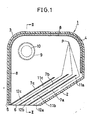
- a closed container 1 comprises a hollow, flat, approximately rectangular body made of a plastics sheet material, with one corner cut across and a slant plate 2 closing off the corner portion, a corner portion 3 located diagonally opposite to the cut corner portion and another corner portion 4 positioned between the two corner portions 3.
- the extent to which the corner portion 4 is curved is such as to form a quarter cylindrical surface shape.
- an opening 6 is provided between the remaining corner 5 and the slant plate 2.
- a number of partition plates 7 parallel to the slant plate 2 are arranged at predetermined spaces within the container 1, extending from the opening 6 toward the interior of the container.
- the container 1 is internally lined with a soft elastomeric sound absorbing material 8 such as a polyurethane foam lining.
- a circular tube 9 is connected to the side wall of the container 1 at a location adjacent the corner portion 3.
- the elastomeric sound absorbing lining 8 extends into the tube 9 to line its internal surface.
- the end portion 10 of the circular tube 9 remote from the container 1 is open.
- the lengths of the respective partition plates 7a, 7b, 7c ... are selected so that the passages 11 a, 11b, 11c ... which they define therebetween have a length which when added to the distance from the end of the passage within the container to a predetermined position P within the container 1 will give the same value in each case.
- the surface common to the internal end surfaces (enveloping surface) of the respective partition plates 7a, 7b, 7c ... having the lengths determined as aforesaid will be convex.
- the sounds passing through the respective passages 11a, 11b, 11c ... are converged to the point P according to Huygen's principle.
- an arbitrary position P away from the mounting position of the circular tube 9 is determined to be within the container 1. Then, centre line 12a of the passage 11 a between the partition plate 7a closest to the slant plate 2 and the slant plate 2 itself is forwardly extended from the forwardmost end Qa of the passage and a point Ra is obtained on the centre line 12a that satisfies the following relation. Then, a line X is drawn parallel to the opening 6 from the point Ra.
- the points at which the centre lines 12b, 12c, 12d ... of the respective passages 11b, 11c, 11d ... and the line X intersect are set to be Rb, Rc, Rd ....
- a sound from within the room arrives at the opening 6 of the container 1, the sound passes through the passages 11a, 11b, 11c c ..., arrives at the free space within the container 1, is refracted at the end portions Qa, Qb, Qc ... of the passages 11a, 11b, 11c ... by Huygen's principle, and is converged to the point P within the container 1.
- the sums of the respective lengths of the passages 11 a, 11b, 11 c ... and the respective distances QaP, QbP, QcP ... from the end portions Qa, Qb, Qc ... to the point P are always the same.
- the slit shaped passages 11 are formed by the partition plates 7 extending parallel to the slant plate 2.
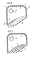
- a screen board 13 may be set up to the end of the opening 6 adjacent the corner 5 to extend towards the interior of the container 1 parallel to the slant plate 2.
- a sound wave delaying member 14 made of a ceramic foam material is inserted between the slant plate 2 and the screen board 13, the internal end surface of the sound wave delaying member 14 being formed in a lens shape in the same manner as the ends of plates 7, according to the principle generally set out in connection with Figure 4.
- a ceramic foam material is used to form the sound wave delaying member 14.
- other materials such as metal foam, a mass of metal fibres or particles, a mass of ceramic particles or a resin hardened foam (cross - linked synthetic plastics foam) having a small mass made up of cell wall-forming material may be employed.
- the slit shaped passage 12 of the device shown in Figures 1 to 4 may be occupied by a sound wave delaying member 14 as shown in Figure 7 which is effectively a combination of the sound wave delaying member of Figure 6 and the partition plates 7.
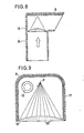
- a sound delaying member 16 shaped like a piano-convex lens is provided adjacent the angle of a tubular container 15 bent in a letter "L" shape and the sound -absorbing lining 8 is provided on the surface opposite the sound wave delaying member 16. The sound converged by this sound wave delaying member 16 is absorbed by the sound absorbing member 8.
- a planar-convex lens shaped sound delaying member 16' is provided at an opening portion 18 of a container 17 of hollow flat body shape.
- a circular tube 19 is mounted at a location away from a converging point P for sound in similar manner to circular tube 9 of Figures 1 to 3.
- the wave delaying members 16 and 16' of Figures 8 and 9 may be formed of the materials indicated hereinbefore for the wave delaying members 14 and 14'.
- the sound insulating device of the present invention may be applied not only to a ventilator but also to, for example, an exhaust port for discharging gases other than air or air-containing gas mixtures.
Landscapes
- Physics & Mathematics (AREA)
- Acoustics & Sound (AREA)
- Engineering & Computer Science (AREA)
- Architecture (AREA)
- Electromagnetism (AREA)
- Civil Engineering (AREA)
- Structural Engineering (AREA)
- Building Environments (AREA)
- Exhaust Silencers (AREA)
- Pipe Accessories (AREA)
- Soundproofing, Sound Blocking, And Sound Damping (AREA)
Claims (8)
Applications Claiming Priority (2)
| Application Number | Priority Date | Filing Date | Title |
|---|---|---|---|
| JP59126506A JPS616493A (ja) | 1984-06-21 | 1984-06-21 | 防音装置 |
| JP126506/84 | 1984-06-21 |
Publications (3)
| Publication Number | Publication Date |
|---|---|
| EP0165760A2 EP0165760A2 (fr) | 1985-12-27 |
| EP0165760A3 EP0165760A3 (en) | 1986-06-04 |
| EP0165760B1 true EP0165760B1 (fr) | 1989-01-11 |
Family
ID=14936890
Family Applications (1)
| Application Number | Title | Priority Date | Filing Date |
|---|---|---|---|
| EP85304149A Expired EP0165760B1 (fr) | 1984-06-21 | 1985-06-12 | Dispositif d'isolation acoustique |
Country Status (5)
| Country | Link |
|---|---|
| US (1) | US4605091A (fr) |
| EP (1) | EP0165760B1 (fr) |
| JP (1) | JPS616493A (fr) |
| KR (1) | KR860000455A (fr) |
| DE (1) | DE3567494D1 (fr) |
Families Citing this family (10)
| Publication number | Priority date | Publication date | Assignee | Title |
|---|---|---|---|---|
| KR20020063090A (ko) * | 2001-01-26 | 2002-08-01 | 강철 | 창문 덧붙이 환기식 방음장치 |
| US10490178B2 (en) * | 2003-12-22 | 2019-11-26 | Bonnie S. Schnitta | Perforation acoustic muffler assembly and method of reducing noise transmission through objects |
| US7431127B2 (en) * | 2004-09-21 | 2008-10-07 | Durr Systems, Inc. | Compact noise silencer for an air blower |
| US20070045042A1 (en) * | 2005-08-25 | 2007-03-01 | L&L Products, Inc. | Sound reduction system with sound reduction chamber |
| CN101309756B (zh) | 2005-11-15 | 2012-07-25 | 松下电器产业株式会社 | 静电雾化装置与静电雾化系统 |
| JP4779939B2 (ja) * | 2005-11-15 | 2011-09-28 | パナソニック電工株式会社 | 静電霧化装置及び静電霧化システム |
| JP2008025233A (ja) * | 2006-07-21 | 2008-02-07 | Mk Seiko Co Ltd | 消音装置 |
| JP2008144392A (ja) * | 2006-12-07 | 2008-06-26 | Mk Seiko Co Ltd | 消音装置 |
| JP4996535B2 (ja) * | 2008-05-08 | 2012-08-08 | タイガースポリマー株式会社 | 吸音ダクト |
| RU2656419C1 (ru) * | 2017-09-15 | 2018-06-05 | Олег Савельевич Кочетов | Акустический кожух |
Family Cites Families (8)
| Publication number | Priority date | Publication date | Assignee | Title |
|---|---|---|---|---|
| US1964845A (en) * | 1933-09-14 | 1934-07-03 | American Telephone & Telegraph | Ventilator |
| GB610841A (en) * | 1946-01-21 | 1948-10-21 | Likuvag A G | Improvements in or relating to sound damping and silencing devices for gaseous currents |
| FR1217917A (fr) * | 1958-12-13 | 1960-05-06 | Ile B L G Soc Civ | Perfectionnements apportés aux silencieux, notamment à ceux équipant les conduites d'échappement des moteurs à combustion interne |
| FR1580553A (fr) * | 1968-07-26 | 1969-09-05 | ||
| US3508838A (en) * | 1968-09-16 | 1970-04-28 | Gen Electric | Sound suppression of compressors used in gas turbine engines |
| FR2082281A5 (fr) * | 1970-03-10 | 1971-12-10 | Ledentu Andre | |
| US4418788A (en) * | 1981-04-13 | 1983-12-06 | Mitco Corporation | Branch take-off and silencer for an air distribution system |
| US4432434A (en) * | 1982-01-07 | 1984-02-21 | Tempmaster Corporation | Sound absorbing arrangement for air handling units |
-
1984
- 1984-06-21 JP JP59126506A patent/JPS616493A/ja active Pending
-
1985
- 1985-06-07 US US06/742,508 patent/US4605091A/en not_active Expired - Lifetime
- 1985-06-10 KR KR1019850004069A patent/KR860000455A/ko not_active Ceased
- 1985-06-12 EP EP85304149A patent/EP0165760B1/fr not_active Expired
- 1985-06-12 DE DE8585304149T patent/DE3567494D1/de not_active Expired
Also Published As
| Publication number | Publication date |
|---|---|
| EP0165760A3 (en) | 1986-06-04 |
| KR860000455A (ko) | 1986-01-29 |
| JPS616493A (ja) | 1986-01-13 |
| US4605091A (en) | 1986-08-12 |
| EP0165760A2 (fr) | 1985-12-27 |
| DE3567494D1 (en) | 1989-02-16 |
Similar Documents
| Publication | Publication Date | Title |
|---|---|---|
| CA2093534C (fr) | Appareil de traitement de l'air adaptable a l'entree et la sortie d'un ventilateur | |
| US4433751A (en) | Sound suppressor liner | |
| EP1131502B1 (fr) | Dispositif d'attenuation de bruit | |
| KR0131998B1 (ko) | 흡입패널과 정류가이드 및 이들을 사용하는 송풍장치 | |
| EP0649486B1 (fr) | Chambre sourde et elements structurels anechoiques | |
| US3866001A (en) | Structural block with septum | |
| EP0165760A2 (fr) | Dispositif d'isolation acoustique | |
| US5780785A (en) | Acoustic absorption device and an assembly of such devices | |
| US4842097A (en) | Sound absorbing structure | |
| JP7344665B2 (ja) | 換気用開口構造 | |
| KR100229250B1 (ko) | 음향감쇠기 | |
| EP0265000B1 (fr) | Dispositif de ventilation silencieux, notamment pour une ouverture de ventilation dans un mur ou une cloison | |
| US4572327A (en) | Sound attenuator | |
| GB1575062A (en) | Element for absorption of sound energy | |
| EP0860553A2 (fr) | Mur antibruit | |
| JPH08246421A (ja) | レゾネータ型防音パネル | |
| EP0754901B1 (fr) | Dispositifs d'atténuation de bruit, leur fabrication et leur utilisation pour l'atténuation de bruit dans les canalisations | |
| JPH09198052A (ja) | 吸音板材 | |
| JP3301680B2 (ja) | 吸音構造体 | |
| JPS6315710Y2 (fr) | ||
| JPH0260944B2 (fr) | ||
| JPH0925671A (ja) | 共鳴型吸音板 | |
| JPS621494B2 (fr) | ||
| AU767046B2 (en) | Noise attenuation device | |
| CA2208190C (fr) | Appareil de traitement de l'air pour l'entree et la sortie d'air d'un ventilateur |
Legal Events
| Date | Code | Title | Description |
|---|---|---|---|
| PUAI | Public reference made under article 153(3) epc to a published international application that has entered the european phase |
Free format text: ORIGINAL CODE: 0009012 |
|
| AK | Designated contracting states |
Designated state(s): DE FR GB |
|
| PUAL | Search report despatched |
Free format text: ORIGINAL CODE: 0009013 |
|
| AK | Designated contracting states |
Kind code of ref document: A3 Designated state(s): DE FR GB |
|
| 17P | Request for examination filed |
Effective date: 19860815 |
|
| 17Q | First examination report despatched |
Effective date: 19871006 |
|
| GRAA | (expected) grant |
Free format text: ORIGINAL CODE: 0009210 |
|
| AK | Designated contracting states |
Kind code of ref document: B1 Designated state(s): DE FR GB |
|
| REF | Corresponds to: |
Ref document number: 3567494 Country of ref document: DE Date of ref document: 19890216 |
|
| ET | Fr: translation filed | ||
| PLBE | No opposition filed within time limit |
Free format text: ORIGINAL CODE: 0009261 |
|
| STAA | Information on the status of an ep patent application or granted ep patent |
Free format text: STATUS: NO OPPOSITION FILED WITHIN TIME LIMIT |
|
| 26N | No opposition filed | ||
| PGFP | Annual fee paid to national office [announced via postgrant information from national office to epo] |
Ref country code: GB Payment date: 19920505 Year of fee payment: 8 |
|
| PGFP | Annual fee paid to national office [announced via postgrant information from national office to epo] |
Ref country code: FR Payment date: 19920609 Year of fee payment: 8 |
|
| PGFP | Annual fee paid to national office [announced via postgrant information from national office to epo] |
Ref country code: DE Payment date: 19920702 Year of fee payment: 8 |
|
| PG25 | Lapsed in a contracting state [announced via postgrant information from national office to epo] |
Ref country code: GB Effective date: 19930612 |
|
| GBPC | Gb: european patent ceased through non-payment of renewal fee |
Effective date: 19930612 |
|
| PG25 | Lapsed in a contracting state [announced via postgrant information from national office to epo] |
Ref country code: FR Effective date: 19940228 |
|
| PG25 | Lapsed in a contracting state [announced via postgrant information from national office to epo] |
Ref country code: DE Effective date: 19940301 |
|
| REG | Reference to a national code |
Ref country code: FR Ref legal event code: ST |