EP0165817A2 - Assemblage pour l'éclairage - Google Patents
Assemblage pour l'éclairage Download PDFInfo
- Publication number
- EP0165817A2 EP0165817A2 EP85304414A EP85304414A EP0165817A2 EP 0165817 A2 EP0165817 A2 EP 0165817A2 EP 85304414 A EP85304414 A EP 85304414A EP 85304414 A EP85304414 A EP 85304414A EP 0165817 A2 EP0165817 A2 EP 0165817A2
- Authority
- EP
- European Patent Office
- Prior art keywords
- assembly
- light
- mirror
- case
- lighting
- Prior art date
- Legal status (The legal status is an assumption and is not a legal conclusion. Google has not performed a legal analysis and makes no representation as to the accuracy of the status listed.)
- Withdrawn
Links
Images




Classifications
-
- B—PERFORMING OPERATIONS; TRANSPORTING
- B60—VEHICLES IN GENERAL
- B60R—VEHICLES, VEHICLE FITTINGS, OR VEHICLE PARTS, NOT OTHERWISE PROVIDED FOR
- B60R1/00—Optical viewing arrangements; Real-time viewing arrangements for drivers or passengers using optical image capturing systems, e.g. cameras or video systems specially adapted for use in or on vehicles
- B60R1/12—Mirror assemblies combined with other articles, e.g. clocks
- B60R1/1207—Mirror assemblies combined with other articles, e.g. clocks with lamps; with turn indicators
-
- B—PERFORMING OPERATIONS; TRANSPORTING
- B60—VEHICLES IN GENERAL
- B60Q—ARRANGEMENT OF SIGNALLING OR LIGHTING DEVICES, THE MOUNTING OR SUPPORTING THEREOF OR CIRCUITS THEREFOR, FOR VEHICLES IN GENERAL
- B60Q3/00—Arrangement of lighting devices for vehicle interiors; Lighting devices specially adapted for vehicle interiors
- B60Q3/20—Arrangement of lighting devices for vehicle interiors; Lighting devices specially adapted for vehicle interiors for lighting specific fittings of passenger or driving compartments; mounted on specific fittings of passenger or driving compartments
- B60Q3/258—Rear-view mirrors
-
- B—PERFORMING OPERATIONS; TRANSPORTING
- B60—VEHICLES IN GENERAL
- B60Q—ARRANGEMENT OF SIGNALLING OR LIGHTING DEVICES, THE MOUNTING OR SUPPORTING THEREOF OR CIRCUITS THEREFOR, FOR VEHICLES IN GENERAL
- B60Q3/00—Arrangement of lighting devices for vehicle interiors; Lighting devices specially adapted for vehicle interiors
- B60Q3/80—Circuits; Control arrangements
Definitions
- This invention relates to rearview mirror assemblies for vehicles and, more particularly, to rearview mirror assemblies in which light sources are provided for illumination of inteiror portions of the vehicle in which the assembly is mounted.
- Vehicles with conventional, permanent tops or roofs can easily provide interior map and/or courtesy lighting from the roof area via dome lights or the like which shine downwardly and forwardly or rearwardly over the shoulders of the driver or passengers to enable the reading of maps, books of the like, as well as to light the interior when entering the vehicle.
- dome lights or the like which shine downwardly and forwardly or rearwardly over the shoulders of the driver or passengers to enable the reading of maps, books of the like, as well as to light the interior when entering the vehicle.
- the conventional practice of providing interior lighting from the roof area of the vehicle interior is difficult or impossible to accomodate.
- CA-A-551,492 a hollow box-like structure having a rearwardly facing mirror glass supported adjacent a pair of light bulbs mounted within the interior of the box. The generated light shines downwardly through a translucent panel fitted along the bottom of the box or housing.
- a single light bulb is positioned in a laterally shiftable manner within a metallic mirror case through the bottom of the case.
- the case conducts electricity and serves as a ground connection to complete the circuit through the bulb.
- a lens supported beneath the bulb on the shiftable support holding the bulb directs light downwardly when the shiftable support is moved into contact with the metallic mirror housing.
- a further problem encountered with prior structures of this type has been the leakage or misdirection of light toward the front of the vehicle in which the rearview mirror assembly is mounted. This causes illumination of instrument panel areas of the vehicle or other undesired areas.
- such structures have been prone to light leakage visible to the driver or passengers which, when coupled with illumination of undesired areas of the vehicle, can serve as a significant distraction to the driver or passenger thereby also creating a safety hazard.
- lighted vanity mirrors do not provide a solution to the problem of general interior and/or courtesy lighting for use for reading by the driver or passengers or the provision of courtesy lighting during entrance into the vehicle since they are primarily directed to illuminating the face of a person using the vanity mirror. Accordingly, lighted vanity mirrors do not provide a solution to the interior lighting problems mentioned above.
- a rearview mirror vehicle lighting assembly comprises a mirror case for a mirror, and means for supporting the assembly in a vehicle, the case having a front opening through which the mirror element is visible; and a light source; characterised in that the case back comprises an opening therethrough; the bottom edge of the case comprises an opening therethrough; and the assembly includes closure means for covering the opening through the case back and housing means for supporting the light source within the case in a position to provide light shining downwardly and out the bottom edge of the case.
- the closure means is a housing secured on the case back, the housing being hollow, having a rear wall spaced from the case back, and tightly engaging the exterior of the miror case around the periphery of the openings in the case back and bottom edge to prevent light leakage therebetween.
- a light directing means is preferably included.
- a rearview mirror.vehicle lighting assembly comprises lighting means for illuminating areas adjacent the assembly; and a mirror case with a back for a mirror characterised by the case back being spaced from the mirror element and having at least one opening therethrough into the space between the mirror element and the case back; housing means secured on the exterior of the mirror case for supporting the lighting means within the space through the opening in the case back, the housing means including closure means for covering the opening in the case back; and light directing means for directing the light from the lighting means outwardly of the assembly.
- the light directing means in either aspect of the present invention is preferably in the form of a lens positioned beneath the light source, and reflector means extending around the light source for reflecting light therefrom downwardly toward the lens.
- the reflector means is preferably a metal housing which reflects light from the light source and also serves as a heat sink to dissipate heat from the light source and comprises means engaging the housing means preventing shifting of the reflector means when positioned in the assembly.
- the case back comprises a pair of openings therethrough, one on either side of the centre of the case back; the housing means comprising means for supporting lighting means within both the openings and closure means for covering both the openings.
- light directing means are included comprising means for directing light from the lighting means downwardly of the assembly, toward the side of the assembly comprising the mirror laterally outwardly of the ends of the assembly and laterally inwardly toward a plane extending through the centre of the assembly, the light directing means causing illumination of a first magnitude of first and second areas below and adjacent either lateral end of the assembly and on the one side of the assembly comprising the mirror, and illumination of a second and greater magnitude than the first magnitude of a third area intermediate the first and second areas and on the one side of the assembly, but minimizing illumination of areas on the side of the case back which is opposite the one side.
- a rearview mirror vehicle lighting assembly comprises a mirror case for a mirror, a case back, lateral ends, and means for supporting the assembly in a vehicle; lighting means for illuminating areas adjacent the assembly; characterised by support means for supporting the lighting means on the mirror case; and light directing means for directing light from the lighting means to illuminate first and second areas below, adjacent either lateral end, and on the one side of the assembly on which the mirror element is located with a first amount of light, and a third area intermediate the first and second areas and aligned centrally of and on the one side of the assembly with a second amount of light which is greater than the first amount, the light directing means generally minimizing illumination of areas on the side opposite the one side of the assembly where the case back is located.
- the light directing means comprises means for directing a greater amount of light in the first, second and third areas in a position spaced outwardly away from the one side of the assembly than in a direction directly downwardly from the assembly.
- the third aspect of the present invention may be combined with either the first or second aspect of the present invention.
- the compatible features of the first and second aspects of the present invention may be combined and similarly all three aspects of the present invention may be combined.
- the present invention provides a compact, rearview/mirror lighting arrangement which provides at least in the preferred embodiments proper and.sufficient amount of light for both the driver and front seat passenger of a vehicle and a somewhat greater amount of light for the centre or console area between the drive and passenger in the seating area of the vehicle.
- the present invention minimizes illumination of undesired areas such as the crash pad on top of the instrument panel of the vehicle, substantially avoids illumination panel, while preventing light leakage which can distract the driver or passengers.
- the light source or sources in the present assembly are not directly visible to the driver or passenger.
- the present invention provides, at least in the preferred embodiments, proper heat dissipation for any heat build up from use of the light in the assembly, avoids hot spots in the assembly which could burn or injure users of the assembly, and yet has minimal weight and even, uniform mass distribution which avoids significant vibration which could otherwise detract from proper vision and use of the rearview mirro vehicle lighting assembly.
- the present preferred rearview mirror vehicle lighting assembly also includes an appropriate lighting structure without affecting the appearance of the mirror assembly when viewed by the driver or passenger and does not affect the connection or support of the mirror assembly on the vehicle in its normal position. Further, attachment and access to the lighting assembly may be provided through the back of the associated mirror case for repair and/or maintenance while avoiding obstruction of the desired lighting from the bottom of the assembly.
- a rearview mirror vehicle lighting assembly including a mirror case having a back, top, bottom and end edges and including a mirror element.
- the case back is spaced from the mirror element and has at least one opening through the case back into the space between the mirror element anc case back.
- Means for supporting the assembly on a vehicle are also provided.
- lighting means for illuminating areas adjacent the assembly and housing means secured on the exterior cf the mirro case for supporting the lighting means within the space through the opening in the case back are included.
- the housing means also include a closure means for covering the opening in the case back.
- light directing means for directing light from the lighting means outwardly of the assembly are provided.
- housing or cover members are included over one or more openings in the back of the mirrorcase.
- the housing or cover members support lights or light sources shining directly downwardly through openings in the bottom of the housing or cover members.
- the light directing means may include reflector housings for directing light downwardly through lenses supported beneath one or more light sources mounted in the housing means.
- Such lenses provided the important feature of adequate and proper lighting for both the driver and passenger areas of the front vehicle seating area by directing light downwardly and toward the side of the assembly on which the mirror element is located while," at the same time, directing light laterally outwardly toward both ends of the assembly and laterally inwardly toward a line passing through the centre of the assembly.
- Such light direction creates various zones of specific light intensity for the driver and passenger.
- the centre or console area between the driver and passenger is provided with a greater amount of light while illumination of the crash pad area is minimized and illumination of the instrument panel areas of the vehicle is substantially avoided.
- the assembly includes appropriate wiring extending through the housing secured on the back of the mirror case for connection to an electrical source in the vehicle, appropriate switching to control the operation of the lighting assembly, and means for preventing light leakage between the housing and mirror case to avoid distracting light.
- the housing is easily removable for access and repair purposes.
- a rearview mirror assembly for use in vehicle such as automobiles or trucks or the like is coupled with a lighting assembly such that the combined assembly cooperates to produce a lightweight, optically efficient, rearview mirror assembly with minimal vibration while simultaneously providing the capability of reading or map and/or coutesy lighting within a vehicle from the rearview mirror location while minimizing illumination of undesired portions of the vehicle interior such as the crash pad over an instrument panel while substantially avoiding illuminatioan of the instrument panel itself.
- Such illumination is also provided without distracting light leakage into the eyes of the driver or areas other than the desired lighting areas.
- each embodiment of the invention includes a rearview mirror and mounting bracket assembly of the type designed for day/night operation in which the intensity of reflected light may be reduced to eliminate glare during night driving.
- the day/night rearview mirror assembly used for both embodiments is of the type shown and described in U.S.-A-4,436,371.
- That day/night vehicle mirror assembly includes a mounting bracket 11 which is of a known type including a pair of ball joints 12, 13 ( Figure 2) received within a cylindrical casing.
- the ball member 12 is connected to a casting or support member 14 adapted for receipt over a retainer or button mounted on the inside surface of a windshield to support the rearview mirror assembly in viewing position.
- the double ball joint mounting bracket allows pivotal adjustment of the position of the mirror to accommodate drivers of all sizes and enables adjustment of the positioning of the lighted areas obtained with the rearview mirror/vehicle lighting assembly of the present invention.
- the mirror assembly also includes a moulded, one-piece, resinous plastics case 15 having a mirror element 24 ( Figure 6) and an overcentre, toggle type, day/night pivot actuator 26 which pivots the mirror case and mirror element with respect to the mirror mounting bracket 11 between precisely located day and night reflecting positions.
- a preferred material for the case 15 and actuator 26 is polypropylene.
- the mirror element 24 is spaced from the back 16 of the moulded, resinous mirror case 15 to provide an internal area or space which, in the present invention, is utilized for receipt of the lighting assembly. That space also reduces the weight of the overall rearview mirror/vehicle lighting assembly.
- the mirror case 15 includes a continuous, peripheral side wall forming top, bottom and lateral end edges 17 to 20 ( Figures 1 to 6). These edges end in a continuous moulded lip 23 ( Figure 6) on the side of the mirror case 15 opposite the case back 16 and define an opening which receives the mirror element 24.
- the day/night actuator 26 is received within the space between the mirror element 24 and the case back 16 on support members as described in U.S.-A-4,436,371 for actuation by a pivot member 28 between day and night positions.
- the pivot member 28 projects downwardly through an opening extending through the case back 16 and the bottom edge 18 in a central position on the mirror assembly ( Figures 1 and 3 to 5).
- the case back 16 also includes a pair of generally rectangular cutouts or openings 30 extending through the back of the case laterally intermediate the pivot member 28 and either lateral end 19, 20 of the mirror assembly.
- the openings 30 extend continuously into and communicate with openings 32 extending through the bottom edge 18 of the mirror case in alignment with the openings 30 ( Figure 6).
- the combined openings 30, 32 receive portions of a lighting assembly 40 when secured to the exterior of the back 16 as described more fully hereinafter.
- the lighting assembly 40 which is adapted for coupling to the back of the mirror case 15, includes a lens housing 42 having lighting support portions 44, 46 and a connecting portion 48 of lesser width than the portions 44, 46 extending between the inner surfaces of the lighting support portions 44, 46.
- the entire lens housing 42 is preferably moulded in one-piece from a resinous, thermoplastic material such as polycarbonate.
- the preferred colour for the polypropylene and polycarbonate materials used to manufacture the mirror case, actuator and lens housing is black so as to reduce reflected light from the case and lens housing and thus reduce glare to the driver of a vehicle in which the assembly is mounted.
- other coloured materials such as those keyed to the vehicle interior colour can also be used.
- Polycarbonate resinous material is preferably used for the lens housing 40 since it has a higher heat deflection temperature and thus a higher heat resistance which can better withstand the temperatures generated by the light sources mounted within the present invention.
- the mirror case 15 need not be formed from polycarbonate because the mirror case portions adjacent the lighting assemblies are spaced sufficiently away to avoid such heat problems and are also protected by reflector heat sink housings 100 extending around light sources 98 as described below.
- the heat deflection temperature of the preferred polypropylene (4 E 31A from Eastman Chemical Products Inc.) is 79°C at 455 kPa (175 degrees F. at 66 psi) and 57°C at 1820 k P a (134 degrees F. at 264 psi) under ASTM Test D648.
- the heat deflection temperature for the preferred polycarbonate is 138°C at 455 kPa (280 degrees F. at 66 psi) and 129°C - 138°C at 1820 kPa (265-280 degrees F. at 264 psi) under the same ASTM test.
- the maximum temperature expected to be encountered with this assembly, even when lighted for extended periods, is about 37.7°c (100 degrees F.) above the ambient temperature of the mirror location.
- the lens housing 42 is generally hollow and U-shaped in cross- section, and has a generally vertically extending back 50 and a generally horizontally extending bottom edge 52 when mounted on the mirror case 15.
- a continuous end edge 54 ( Figures 7 and 9) extends around the top and ends of the lens housing 40 at the end of an in-turned flange at the top and ends of the back 50.
- the continuous edge 54 is contoured to the shape of the back 16 of the mirror case 15 such that it tightly abuts the case back 16 around the periphery of the cutouts 30, 32 to effectively seal and prevent light leakage from within the case when the light sources are actuated.
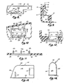
- a free end edge 70 of the bottom wall 52 extends beyond and overlaps the edge of the opening 32 as explained below and as shown in Figure 12.
- Such tight engagement and overlap is made effective by the removable securing structure for fastening the lens housing 42 to the back of the mirror case as is also described below.
- the hollow interior of the lens housing 42 within the border provided by the edges 54, 70 provides a space for mounting and supporting the lighting assemblies-which are received in the cutouts 30, 32 as well as a space for receiving the wires, switches and electrical connectors which provide electrical power to the lighting assemblies.
- Such wiring and components are thus concealed from view from the assembly exterior as well as being effectively confined by the lens housing against the case back 16.
- each of the bottom walls 52 of the lighting support portions 44, 46 is provided a rectangular lens opening 56 best seen in Figures 10 to 12.
- a recess 58 is provided around generally the entire periphery of the lens opening 56 except for a locating tab or detent 60 at the inner end of each rectangular lens opening.
- the locating tab 60 positions a lens element 150 (Figure 15) which is designed to include specific optical surfaces to direct light in a predetermined manner when received in the lens opening 56 and surrounding recess 58.
- stiffening supports ribs 64a and b, 66a and b and 68a and b ( Figure 10).
- the ribs 64b, 66b and 68b are interconnected by and are formed on top of an upstanding wall 65 which parallels the edge of the opening 56 and extends slightly inside that edge ( Figure 12).
- the ribs 64, 66, 68 and the wall 65 include projecting end or vertical surfaces 64c, 66c, 68c, and 65a which extend slightly inside the outline of the rectangular lens opening ( Figures 11 and 12). Those projecting end surfaces and the wall 65 terminate above the level of the inside surface of the bottom wall 52 of the lighting support portions surrounding the lens opening 56 to provide a small gap or space "X" ( Figure 12).
- the gap "X" on both of the longer sides of the opening 56 receives a thin flange from one of the reflector housings 100 to hold that reflector housing in place aswill be more fully described hereinafter.
- one of the rib ends preferably the rib end 64c, is slightly longer than the other rib ends 66c, 68c or face 65a of the wall 65 such that it may project into a corresponding slot in the reflector housing as is also described below.
- the ribs 64a, 66a and 68a extend toward the vertical back wall 50 of the lens housing 42 from the edge of the lens opening and merge into that rear wall to provide a bracing structure which rigidifies the entire lens housing.
- outwardly projecting flanges 64e, 66e and 68e extend beyond a vertical outside face 67 of the wall 65 ( Figure 12).
- the outer edge 70 of the bottom wall 52 of the lens housing projects beyond the vertical face 67, and has a rounded contour visible from the front of the overall rearview mirror/vehicle lighting assembly when complete.
- the lower edge of the opening 32 is received between the projecting rib portions 64e, 66e and 68e and the projecting bottom wall edge 70 and against the vertical face 67 of the wall 65 in a tongue and groove fashion to firmly lock the lens housing lower edge in position with respect to the lower edges of the openings 32 to both prevent light leakage and to firmly retain the light assemblies in place.
- a lighting assembly or support is mounted immediately above each lens opening 56 in each lighting support portion 44, 46 of the lens housing 42.
- the lighting assemblies each include a lamp or bulb socket 80 riveted to a steel retainer bracket 82 which is preferably formed from steel and plated with cadmium or zinc for corrosion protection.
- the bracket 82 includes a base 84 having an aperture therethrough adapted to receive an extending stake or post 86 moulded on the interior of the lens housing 42 in position to receive the bracket base 84.
- the stake or post 86 is heat formed to create a head which retains the bracket in place.
- a screw can be received through the base 84 and sunk into the vertically extending back of the lens housing 42 to retain the bracket in place.
- a secondary post 86 positioned in a second aperture or an extension of the main aperture through the base 84 to properly align and vertically position the bracket 82 within the lens housing.
- the bracket 82 also includes an upper retaining flange 90 which is angled toward the edge 54 of the upper flange of the lens housing such that a space slightly less than the thickness of the back 16 of the mirror case 15 is created.
- An upper edge 92 of the flange 90 is curved away from the edge 54 to allow the flange 90 to spring outwardly to receive the upper edge of the opening 30 when the lens housing is assembled with the case back 16.
- the lower portion of the bracket 82 includes an L-shaped extension 94, 96.
- the bulb socket or base 80 is riveted to the downwardly extending portion 96 as shown in Figure 9.
- each of the lamp bases 80 is a light source in the form of a conventional 3 candle power incandescent light bul 98 of known structure, although other power bulbs could be used.
- the end of such bulb is preferably of wedge base style to be received within spring clips in the lamp base 80, although screw-in, bayonet or other type bulbs and compatible lamp bases may also be used.
- the bulb 98 is positioned directly over and generally parallel to the plane of the lens opening 56 and the lens 150 when received therein.
- the optical surfaces of the lens can properly orient the light and direct it downwardly and outwardly of the assembly.
- each reflector housing 100 Positioned over and around each of the lamp bases 80 and bulbs 98 is a reflector housing 100 preferably stamped from low carbon sheet steel and plated with tin for corrosion protection and to provide a relatively shiny, light reflective surface, at least on the inside surface thereof.
- the reflector housings 100 which are mirror images of one another, are best seen in Figures 7, 13 and 14.
- Each reflector housing 100 includes a pair of slightly tapering side walls 102, 104 and a closed end wall 106 which slants inwardly as it progresses toward the rounded top surface 108.
- the end opposite the closed end wall 106 is open and is adapted to receive the bulb and bulb base when the housing is slid thereover and secured by the ribs 64, 66 and 68 adjacent the lens opening 56.
- the side wall 102 of the reflector housing 100 also includes a vertically extending slot 110 adapted to receive the extending rib 64c to position the reflector housing against lateral shifting, as well as an outwardly extending lower flange 112 which fits within the space "X" below the rib extensions 64c and d, 66c and d, and 68c and d.
- a rectangular recess or cutout 114 is also provided adjacent the open end of the housing 100 to allow receipt of the bulb base 80 when the housing is slid thereover as shown in Figure 7.
- the sides 102, 104 of the reflector housings 100 are relatively thin and may be squeezed inwardly to allow the flange 112 to be slid under the retaining ribs 64, 66, 68 until the slot 102 is in registry with the extension of the rib 64 at which point pressure on the sides is released and they spring outwardly intc proper position with the cutout 114 fitted around the bulb base 80 and the slot 102 received around. the rib extension 64c to prevent lateral shifting.
- the housings 100 also serve as heat sinks within the lighting assembly to receive or collect and dissipate heat within the assembly to prevent hot spots on the lens housing 42 or any part of the rearview mirror assembly 15.
- Sheet metal housings 100 have a high heat conductivity and readily absorb heat generated by the light bulbs 98 which are in close proximity thereto. Accordingly, melting of any part of the lens housing or the rearview mirror assembly or any backing on the mirror element itself is avoided through such heat dissipation which also provides greater life for the assembly.
- a wiring assembly 115 provides electrical power to each of the light bulbs 98 and allows appropriate switching of such power when desired.
- a switch 120 which may be one of any of several conventional varieties, is preferably a rocker-type, double pole switch obtained under Part No. 62116229 from Carlingswitch, Inc. of West Hartford, Connecticut.
- the switch 120 is positioned adjacent one of the lighting assemblies within one of the lighting support portions 44, 46 of the lens housing 42 through an opening in the bottom wall 52 as shown in Figure 7. It includes a rocker element enabling it to be opened or closed from beneath the lighting assembly and a pair of spring retainer arms which engage the inside surface of the bottom wall 52 of the lens housing 42 after the switch is pressed through the opening therein to hold it tightly in place (Figure 7).
- the wiring assembly 115 also includes a female plug assembly 130 having a plug retainer clip 132 formed-from resinous plastics material receiving and holding a female plug 134 with three electrical terminals adapted to receive a male plug 136 ( Figure 1) from a vehicle power source.
- the clip 132 ( Figures 1 to 3, 7 and 19) includes an annular split ring which may be expanded and mounted around the exterior surface of the double ball mounting bracket cylinder as shown in Figures land 2.
- the female plug 134 When mounted on the bracket 11, the female plug 134 is positioned for convenient attachment to the male plug 136 from the vehicle and yet is substantially hidden behind the rearview mirror assembly such that the electrical connection is substantially hidden from the passenger and driver side of the rearview mirror/ vehicle lighting assembly.
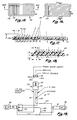
- the typical 12 volt DC power source in a modern vehicle is adapted to be connected via wires 140, 142 to two different terminals on switch 120.
- a ground connection is provided by wire 144 to one terminal of one of the bulb bases 80 and bulbs 98. That ground connection is continued to one terminal on the other bulb base by wire 146, while the second terminal on that other bulb base is connected to the third terminal on the switch and is, in turn, connected to the second terminal on the first bulb base by wire 148.
- the rearview mirror/vehicle lighting assembly 10 may be operated either by throwing the rocker switch 120 to light both the bulbs 98 simultaneously for use in reading maps, books or the like within the car or will light automatically upon the opening of the vehicle doors for use as a courtesy light upon the entrance into the vehicle by a passenger or driver.
- the wires 140 to 148 which extend between the lamp bases 80 and to the female plug 134, are easily received within the hollow connecting portion 48 between the lighting support portions 44, 46 of the lens housing 42 to conceal such wires from the exterior of the assembly 10.
- a small recess or notch 149 is provided immediately below the position of the mirror assembly mounting bracket 11, and is centred in the lens housing 42 ( Figures 7 and 8).
- the three wires 140, 142, 144 can then exit the lens housing to connect to the plug 132 while the bulk of the wiring is concealed within the lens housing but protected from damage or electrical shorting by its encasement within the lens housing.
- Each lens element 150 is moulded from transparent, resinous thermoplastics material such as polycarbonate having a high temperature resistivity and high heat deflection temperature.
- a preferred material is LEXAN LS1-111 clear plastic obtained from General Electric Company, Lexan Products Division, Pittsfield, Massachusetts.
- polycarbonate material can withstand temperatures of between 127 0 C and 138°C (260 degrees F. and 280 degrees F.) before deflecting. Since the temperatures in the present lighting assembly, even after an extended period of use, are not expected to reach above 38°C (100 degrees F.) above ambient temperature, such material will properly withstand with a wide safety margin the temperatures encountered.
- Each lens element 150 has a planar, rectangular shape with a central section 152 including various optical surfaces on its upper and lower surfaces and a surrounding border 154 corresponding in size and shape to the lens opening recess 58 described above in connection with Figures 10 to 12.
- each lens element 150 includes a locating tab receiving recess 156 which receives locating tab 60 formed on one end of each lens opening 56 ( Figure 10).
- each lens element 150 has its optical surfaces oriented to direct the light downwardly and outwardly into selected areas for lighting of the vehicle passenger, driver and console areas, but substantially avoiding lighting of the instrument panel area, minimizing illumination of the crash pad over the instrument panel, and preventing distracting light which would otherwise hinder a driver's vision in th vehicle.
- each lens element 150 two sets of prisms or optical surfaces, each forming Fresnel-type lens sections, are provided on each lens element 150.
- a first set on the lower or underside of each lens element controls the lateral direction of the light from the bulbs 98.
- a second or upper set on the upper surface of each lens element faces internally of the lighting assembly when the lens is mounted therein and controls the vertical direction of the light as it leaves the assembly.
- the first set of optical or lens surfaces extends transverse to the length of the overall lens and includes some 17 prisms or sections. Each prism section has its own draft angle and radius, as well as other prism dimensions which are shown in Figures 17 and 21.
- prism sections A to J for one-half of the lens are set forth in table below.
- the right half of the lens 150 has prism sections which are mirror images of those on the left half and have identical dimensions to those noted in the table.
- the prism width dimension M is the width minus the draft angle (such as draft angle 18 degrees for section F).
- light from the bulb 98 passes downwardly through the lens 150 and is refracted or bent laterally outwardly by the prism sections A to J on both halves of the lens.
- Light passing through the centre of the lens is not bent, while light progressively farther from the centre is bent at progressively greater angles toward the lateral outside ends of the rearview mirror/vehicle lighting assembly as well as laterally inwardly toward the centre of the assembly.
- the upper or internal-surface of the lens 150 has a series of 10 prism sections which extend at right angles to the prism sections A to J on the outer side of the lens.
- the upper lens prism sections are designed to bend light rays from the light source as shown by the representative, dotted light rays in Figure 18 progressively outwardly as they pass downwardly through the lens.
- Prism section 10 is closest to the instrument-panel of the vehicle in assembly 10, while prism section 1 is farthest from the instrument panel.
- prism width M in Figure 18 that prism width includes the draft angle unlike the prism width set forth in Figure 17 for the lower set of prism sections.
- the prism dimensions are shown in Table 1 in millimeters and Table 2 shows the equivalent dimensions in inches for the upper and lower sets of optical surfaces or prism sections on each lens 150 in the preferred embodiment with reference to Figures 17, 18, 20 and 21 are as follows:
- light emanating from the bulbs 98 and reflected downwardly from the inside surface of the reflector housings 100 passes downwardly through the lens elements 150.
- the light is refracted both outwardly toward the vehicle seats from a plane passing directly downwardly through the lenses as shown in Figure 22, laterally outwardly away from the ends of the assembly 10 to illuminate the driver and passenger front seats of the vehicle as shown in Figure 23, as well as laterally inwardly to overlap and illuminate the centre section between the seats or the "console" area between such seats along the centre line of the assembly as shown in Figure 22.
- a lesser amount of light is directed in the area between the plane passing downwardly through the assembly to the front edge of the front seats of the vehicle, or approximately 11 degrees in the typical situation as shown in Figure 22. Accordingly, the lens elements 150 combine to produce lighting in the desired areas as shown in Figures 21 and 22 but do not illuminate undesired areas in the. vehicle all with a substantially low amount of power from low wattage light sources.
- the lighting assembly 40 including the lens housing 43 and associated lighting apparatus in lighting the support portions 44, 46 is designed to be removably secured to the back 16 of the mirror case 15.
- the assembly procedure includes positioning the lens housing 42 behind the back 16 of the mirror case 15 such that the end edges 92 of the retraining brackets 82 are placed inside the upper edges of the openings 30 on the case back 16.
- the lens housing 42 is moved relative to those edges of the openings 30 such that the edges are received between the upper edge 54 and the flange 90 of the brackets 82 as shown in Figure 9.
- the faces 67 of the walls 65 adjacent the lens openings 56 are positioned adjacent the outwardly facing edge of the bottom opening 32 such that the projecting bottom edge 70 of the lens housing engages the bottom edge 18 of the mirror case adjacent the opening 32.
- the lens housing is then moved inwardly such that the edge of the openings 32 engages those wall faces under the rib projections 64e, 66e and 68e in tongue and groove fashion to lock the housing at such lower edges and also to prevent light leakage therethrough.
- sheet metal screws 160 ( Figures 1 and 2) are placed through apertures 162 at either end of the lens housing 42 and inserted through spring metal clips 164 which are wrapped around the lateral edges of the openings 30 in regis try with the apertures 166 in the case back 16.
- the sheet metal screws 160 are then tightened against the clips 164 to pull the peripheral end edges 54 around the lens housing tightly into engagement with the contoured back 16 of the mirror case 15 around the periphery of the apertures 30, 32 to prevent light leakage from such apertures and to securely engage the lens housing with the back of the mirror.
- the electrical wires 140, 142 and 144 leading to the female plug 134 are passed through the notch 149 at the top edge of the lens housing 42 and the retainer 132 is positioned around the mounting bracket 11 to hold the wires and plug in position for connection to the vehicle electrical system.
- the lens housing 42 is completely removable from the back of the mirror case for access to the lighting assemblies therein to change bulbs, replace reflector housings, repair electrical connections or the switch 120 or remove the lens elements 150 as needed.
- the access openings 30 extending through the back of the mirror case allow proper positioning of the lighting assemblies for downward direction of light through the openings 32, the lens openings 56 and the lens elements 150 as described above. when switched on, light is thus directed downwardly and outwardly from the assembly to the driver and passenger seat areas as well as the centre console area as shown in Figures 21 and 22 by the combined action of the reflector housings and the lens elements which direct light from the light sources.
- a second embodiment 170 of the rearview mirror/vehicle lighting assembly including a substantially similar day/night rearview mirror assembly to the rearview mirror assembly of the embodiment 10 including a double ball mounting bracket 11', a day/night pivot actuator 26' and a mirror case 15' all as described above in connection with embodiment 10 in Figures 1 to 22.
- the essential difference between embodiments 10 and 170 is the inclusion in embodiment 170 of two separate lighting assemblies 172, 174 received through separate openings 30' in case back 16' not one continuous lighting assembly 40 as in embodiment 10.
- each includes a generally L-shaped moulded housing or cover also formed from higher temperature resistant polycarbonate and having a rectangular back wall 176, 178 and a rectangular bottom wall 180, 182 extending generally at right angles from the respective back wall and continuously therefrom.
- the bottom walls 180, 182 include light directing openings 184, 186 which are segmented by transversely extending moulded cross bars 188, 190 which prevent the insertion of a finger into the lighting assembly to prevent contact with the hot light source.
- Each housing also has sidewalls 185, 187 and 189, 191 which are contoured to the shape of and have edge surfaces engaging the back 16' of the mirror case around the cut out openings 30', 32' to prevent light leakage.
- the upper edges of the back wall of the housings 176, 178 each include a U-shaped flange 192, 194 adapted to receive and engage in tongue and groove fashion the upper edge of the openings 30' in the case back 16'.
- the flanges 192, 194 ( Figure 25) extend along substantially the entire length of the upper edges of the back walls 176, 178 of the separate housings to securely engage the edge openings and prevent light leakage when the housing is positioned thereover.
- moulded U-shaped flanges or tabs 196a and b are moulded on either side edge of each housing.
- moulded tabs or flanges are also U-shaped and engage the side edge of openings 30' to retain the sides of the housings tightly thereagainst.
- the housings are placed adjacent the openings 30' with the tabs l96a, l96b, 198a, 198b received through edge recesses 33' in the openings 30' ( Figure 25), after which the housings are slid upwardly to engage the flanges 192, 194 and position the U-shaped tabs 196, 198 over the cut out edges when the bottom walls 180, 182 are firmly in e with the bottom edge of the mirror case.
- assemblies 172, 174 are removable in the embodiment 170 to allow bulb replacement or other repair or maintenance, it is possible to permanently fix the housings in place with adhesives or the like in which case the openings 184, 186 would be made large enough to allow bulbs 98' to be changed.
- each assembly 172, 174 Mounted internally within each assembly 172, 174 is a downwardly opening, generally U-shaped, metal, light housing 200, 202 ( Figures 24 and 25).
- the metal housings 200, 202 have polished or reflective inside surfaces and serve as reflector housings and heat sinks as do reflector housings 100 in embodiment 10.
- metal housings 200, 202 are slightly different from one another because the assembly 172 includes a female plug for connecting electrical energy to the assembly while the assembly 174 includes a switch for operating the entire assembly.
- Each housing 200, 202 includes an upper base 204, 206 from which extend downwardly back walls 208, 210 and front walls 212, 214.
- metal housings 200, 202 On either end of the metal housings are end flaps 216 218 bent laterally from the edges of either the front or back walls after being stamped in one piece with the sheet metal of the housing before forming.
- metal housings 200, 202 form box-like structures having no bottom wall such that light can project downwardly therefrom and be reflected by the inside surfaces of the metal housings after formation.
- Each housing 200, 202 is attached by its back wall 208, 210 to the inside of the back housing walls 176, 178 via a moulded protrusion 220 (Figure 24).
- the protrusion 220 extends through an aperture in the metal housing back wall and is heat staked or ultrasonically formed to hold the housing in place with its bottom opening directly positioned above the opening 184 and 186 in the bottom wall 180 or 182 of the covers.
- Mounted within each metal housing 220, 202 is a lamp base and bulb assembly 80', 98' substantially similar to those described above and in connection with embodiment 10. The bulbs are centred within the housings so as to provide heat dissipation space therearound for cooling purposes.
- the bulb bases 80' are mounted to extend downwardly from the upper bases 204, 206 of the metal housings and project generally at right angles to the back of the mirror element and support the bulbs 98' extending downwardly therefrom. When the bulbs 98' are inserted in the sockets 80', the bulbs extend perpendicularly to the plane of the openings 184, 186.
- a female plug receptacle 221 is mounted on the inside surface of the back wall 208 of the metal housing 200 such that it projects through apertures in the back wall 176 of the housing to receive a male connecting plug 222 ( Figure 23) from the vehicle electrical system.
- a slide switch 223 is mounted on the back wall 210 of the metal housing 202. The switch 223 has its operating member 224 projecting through the metal back wall 210 and the back wall 178 of the housing cover for operation of both light assemblies from the rear of the overall assembly.
- the edges of the housings 172, 174 are tightly engaged around the periphery of the openings 30', 32'.
- Light is projected downwardly from the bulbs 98' through the openings at the bottom of the metal housings 200, 202 and through the openings 184, 186 in the bottom walls of the housing covers.
- the bottom openings 32' in the case 15' themselves help direct the light from the bulbs 98'.
- the bottom walls 180, 182 can be eliminated such that the openings 32' would alone direct the light.
- the bottom wall openings 184, 186 also direct the light.
- Such light from the bulbs projects downwardly beneath the assembly, laterally outwardly toward the ends of the assembly, inwardly toward the centre of the assembly as well as outwardly at an angle below the assembly.
- the direction of light is less extensive than in embodiment 10 where lenses are used.
- the wiring in embodiment 170 is essentially connected as in Figure 19 with switching occurring either by the opening of the doors in the vehicle or the use of the switch 223 as described above.
- assemblies 10 or 170 may include different types of light sources such as florescent bulbs, higher wattage incandescent bulbs, or multiple bulbs of the desired type in multiple sockets on either side f the centre line of the assembly. By modifying the optical surfaces on the lens elements in embodiment 10, lighting in specific areas can be adjusted when using any of these bulb combinations.
- different locations and apparatus for connecting vehicle electrical power to the rearview mirror/vehicle lighting assembly other than the plugs 130, 220 may be included, while the lens housings 42, 172, 174 may be adapted and contoured to different shaped rearview mirror assemblies as desired.
Landscapes
- Engineering & Computer Science (AREA)
- Mechanical Engineering (AREA)
- Multimedia (AREA)
- Arrangements Of Lighting Devices For Vehicle Interiors, Mounting And Supporting Thereof, Circuits Therefore (AREA)
Applications Claiming Priority (2)
| Application Number | Priority Date | Filing Date | Title |
|---|---|---|---|
| US06/622,678 US4646210A (en) | 1984-06-20 | 1984-06-20 | Vehicular mirror and light assembly |
| US622678 | 1984-06-20 |
Publications (2)
| Publication Number | Publication Date |
|---|---|
| EP0165817A2 true EP0165817A2 (fr) | 1985-12-27 |
| EP0165817A3 EP0165817A3 (fr) | 1988-01-20 |
Family
ID=24495088
Family Applications (1)
| Application Number | Title | Priority Date | Filing Date |
|---|---|---|---|
| EP85304414A Withdrawn EP0165817A3 (fr) | 1984-06-20 | 1985-06-20 | Assemblage pour l'éclairage |
Country Status (5)
| Country | Link |
|---|---|
| US (1) | US4646210A (fr) |
| EP (1) | EP0165817A3 (fr) |
| JP (1) | JPS6112449A (fr) |
| AU (1) | AU4306185A (fr) |
| CA (1) | CA1263265A (fr) |
Cited By (28)
| Publication number | Priority date | Publication date | Assignee | Title |
|---|---|---|---|---|
| EP0254435A1 (fr) * | 1986-06-26 | 1988-01-27 | Donnelly Corporation | Boîtier pour rétroviseur |
| US4807096A (en) * | 1986-06-26 | 1989-02-21 | Donnelly Corporation | Interior light/carrier module for vehicles |
| GB2192370B (en) * | 1986-06-10 | 1990-02-14 | Mittelhaeuser Bernhard | Internal rear view mirror for motor vehicles |
| EP0719674A3 (fr) * | 1994-12-30 | 1997-05-28 | Donnelly Corp | Montage pour l'éclairage de la console et des instruments d'un véhicule |
| EP0974486A3 (fr) * | 1998-07-24 | 2001-04-18 | Donnelly Hohe GmbH & Co. KG | Dispositif d'éclairage pour véhicule |
| EP0689963B2 (fr) † | 1994-07-01 | 2003-07-02 | Reitter & Schefenacker GmbH & Co. KG | Rétroviseur intérieur pour véhicules automobiles |
| DE10330163A1 (de) * | 2003-07-04 | 2005-02-17 | Daimlerchrysler Ag | Leuchtvorrichtung und Beleuchtungssystem für einen Innenraum eines Kraftfahrzeuges |
| US7195381B2 (en) | 2001-01-23 | 2007-03-27 | Donnelly Corporation | Vehicle interior LED lighting system |
| US7474963B2 (en) | 2000-03-02 | 2009-01-06 | Donnelly Corporation | Navigational mirror system for a vehicle |
| US7586666B2 (en) | 2002-09-20 | 2009-09-08 | Donnelly Corp. | Interior rearview mirror system for a vehicle |
| US7667579B2 (en) | 1998-02-18 | 2010-02-23 | Donnelly Corporation | Interior mirror system |
| US7728721B2 (en) | 1998-01-07 | 2010-06-01 | Donnelly Corporation | Accessory system suitable for use in a vehicle |
| US7815326B2 (en) | 2002-06-06 | 2010-10-19 | Donnelly Corporation | Interior rearview mirror system |
| US7821697B2 (en) | 1994-05-05 | 2010-10-26 | Donnelly Corporation | Exterior reflective mirror element for a vehicular rearview mirror assembly |
| US7826123B2 (en) | 2002-09-20 | 2010-11-02 | Donnelly Corporation | Vehicular interior electrochromic rearview mirror assembly |
| US7832882B2 (en) | 2002-06-06 | 2010-11-16 | Donnelly Corporation | Information mirror system |
| US7855755B2 (en) | 2005-11-01 | 2010-12-21 | Donnelly Corporation | Interior rearview mirror assembly with display |
| US7864399B2 (en) | 2002-09-20 | 2011-01-04 | Donnelly Corporation | Reflective mirror assembly |
| US7871169B2 (en) | 1994-05-05 | 2011-01-18 | Donnelly Corporation | Vehicular signal mirror |
| US7888629B2 (en) | 1998-01-07 | 2011-02-15 | Donnelly Corporation | Vehicular accessory mounting system with a forwardly-viewing camera |
| US7906756B2 (en) | 2002-05-03 | 2011-03-15 | Donnelly Corporation | Vehicle rearview mirror system |
| US7914188B2 (en) | 1997-08-25 | 2011-03-29 | Donnelly Corporation | Interior rearview mirror system for a vehicle |
| US7926960B2 (en) | 1999-11-24 | 2011-04-19 | Donnelly Corporation | Interior rearview mirror system for vehicle |
| US8281857B2 (en) | 2007-12-14 | 2012-10-09 | 3M Innovative Properties Company | Methods of treating subterranean wells using changeable additives |
| US8353344B2 (en) | 2007-12-14 | 2013-01-15 | 3M Innovative Properties Company | Fiber aggregate |
| US8462204B2 (en) | 1995-05-22 | 2013-06-11 | Donnelly Corporation | Vehicular vision system |
| US8596361B2 (en) | 2007-12-14 | 2013-12-03 | 3M Innovative Properties Company | Proppants and uses thereof |
| FR3077541A1 (fr) * | 2018-02-08 | 2019-08-09 | Psa Automobiles Sa | Vehicule automobile equipe d’un dispositif de signalisation d’un mode de roulage du vehicule |
Families Citing this family (116)
| Publication number | Priority date | Publication date | Assignee | Title |
|---|---|---|---|---|
| JPS6336120U (fr) * | 1986-08-23 | 1988-03-08 | ||
| JPS6336121U (fr) * | 1986-08-23 | 1988-03-08 | ||
| US4760500A (en) * | 1987-10-06 | 1988-07-26 | Peng Chang S | Reading light for vehicle |
| US4882565A (en) * | 1988-03-02 | 1989-11-21 | Donnelly Corporation | Information display for rearview mirrors |
| US4905125A (en) * | 1988-08-25 | 1990-02-27 | George Stefan | Anti reflex lamp |
| JP2601334B2 (ja) * | 1988-10-07 | 1997-04-16 | 株式会社小糸製作所 | バニティミラー |
| JPH0374120U (fr) * | 1989-11-15 | 1991-07-25 | ||
| US5481409A (en) * | 1990-02-20 | 1996-01-02 | K. W. Muth Company, Inc. | Mirror assembly |
| US5355284A (en) * | 1990-02-20 | 1994-10-11 | K. W. Muth Company, Inc. | Mirror assembly |
| US5361190A (en) * | 1990-02-20 | 1994-11-01 | K. W. Muth Co. Inc. | Mirror assembly |
| US5014167A (en) * | 1990-02-20 | 1991-05-07 | K. W. Muth Company, Inc. | Visual signaling apparatus |
| US5649756A (en) * | 1991-09-13 | 1997-07-22 | Donnelly Corporation | Rearview mirror with lighting assembly |
| US5178448A (en) * | 1991-09-13 | 1993-01-12 | Donnelly Corporation | Rearview mirror with lighting assembly |
| US5576687A (en) * | 1991-12-20 | 1996-11-19 | Donnelly Corporation | Vehicle information display |
| USD358674S (en) | 1992-12-29 | 1995-05-23 | Ramco Industries, Inc. | Interior vehicle light |
| US5308247A (en) * | 1993-01-21 | 1994-05-03 | Dyrdek Robert D | Electrical connector assembly for automobile rearview mirror and light assembly and method of assembling the same |
| BR9302188A (pt) * | 1993-06-25 | 1995-01-17 | Metagal Ind & Comercio | Aperfeiçoamento em espelho retrovisor interno com luzes de cortesia |
| CA2115872C (fr) * | 1993-08-20 | 2003-11-25 | Antonio Ferreira Do Espirito Santo | Commutateur axial pour circuits electriques |
| USD451456S1 (en) | 1993-08-20 | 2001-12-04 | Metagal Industria E Comercio Ltda. | Internal rearview mirror |
| US5669698A (en) * | 1995-05-24 | 1997-09-23 | Veldman; Roger L. | Modular rearview mirror assembly and method for making same |
| US5842775A (en) * | 1995-11-09 | 1998-12-01 | Westek Associates A California Partnership Of Westek, Inc. | Low profile under cabinet halogen light bar with heat shield |
| US6000823A (en) | 1995-12-11 | 1999-12-14 | Donnelly Mirrors Limited | Rearview mirror assembly |
| US5820245A (en) * | 1995-12-11 | 1998-10-13 | Donnelly Corporation | Rearview mirror assembly |
| USD400481S (en) | 1995-12-11 | 1998-11-03 | Donnelly Corporation | Rearview mirror |
| US6550949B1 (en) | 1996-06-13 | 2003-04-22 | Gentex Corporation | Systems and components for enhancing rear vision from a vehicle |
| US5803579A (en) * | 1996-06-13 | 1998-09-08 | Gentex Corporation | Illuminator assembly incorporating light emitting diodes |
| US20040239243A1 (en) * | 1996-06-13 | 2004-12-02 | Roberts John K. | Light emitting assembly |
| US5788357A (en) * | 1996-08-28 | 1998-08-04 | K. W. Muth Company, Inc. | Mirror assembly |
| US6045243A (en) | 1996-08-28 | 2000-04-04 | K.W. Muth Company, Inc. | Mirror assembly |
| US5984496A (en) * | 1996-11-07 | 1999-11-16 | Malcomson; Kirk | Lighted mirror assembly |
| EP0845390A3 (fr) | 1996-11-29 | 2004-06-09 | Donnelly Corporation | Rétroviseur extérieur modulaire. |
| DE29620775U1 (de) * | 1996-11-29 | 1998-03-26 | Hohe GmbH & Co. KG, 97903 Collenberg | Außenspiegel für ein Fahrzeug |
| DE29621172U1 (de) * | 1996-12-06 | 1998-04-09 | Hohe GmbH & Co. KG, 97903 Collenberg | Außenspiegel mit Sehwinkelerweiterung |
| USD390524S (en) | 1997-06-04 | 1998-02-10 | Donnelly Corporation | Lighted rearview mirror assembly |
| US8294975B2 (en) | 1997-08-25 | 2012-10-23 | Donnelly Corporation | Automotive rearview mirror assembly |
| US6087953A (en) | 1998-02-18 | 2000-07-11 | Donnelly Corporation | Rearview mirror support incorporating vehicle information display |
| AU1947899A (en) * | 1997-12-31 | 1999-07-19 | Gentex Corporation | Vehicle vision system |
| US6278377B1 (en) * | 1999-08-25 | 2001-08-21 | Donnelly Corporation | Indicator for vehicle accessory |
| US8288711B2 (en) | 1998-01-07 | 2012-10-16 | Donnelly Corporation | Interior rearview mirror system with forwardly-viewing camera and a control |
| US6243003B1 (en) | 1999-08-25 | 2001-06-05 | Donnelly Corporation | Accessory module for vehicle |
| US6690268B2 (en) | 2000-03-02 | 2004-02-10 | Donnelly Corporation | Video mirror systems incorporating an accessory module |
| US6428172B1 (en) | 1999-11-24 | 2002-08-06 | Donnelly Corporation | Rearview mirror assembly with utility functions |
| US6693517B2 (en) | 2000-04-21 | 2004-02-17 | Donnelly Corporation | Vehicle mirror assembly communicating wirelessly with vehicle accessories and occupants |
| US6477464B2 (en) | 2000-03-09 | 2002-11-05 | Donnelly Corporation | Complete mirror-based global-positioning system (GPS) navigation solution |
| US6420975B1 (en) | 1999-08-25 | 2002-07-16 | Donnelly Corporation | Interior rearview mirror sound processing system |
| US5984482A (en) * | 1998-07-28 | 1999-11-16 | Gentex Corporation | Mounting assembly for vehicle interior automatic dimming rearview mirror |
| US6005724A (en) | 1998-10-05 | 1999-12-21 | K. W. Muth Company, Inc. | Mirror coating, mirror utilizing same, and a mirror assembly |
| US6076948A (en) * | 1998-10-28 | 2000-06-20 | K. W. Muth Company, Inc. | Electromagnetic radiation emitting or receiving assembly |
| US6257746B1 (en) | 1998-11-03 | 2001-07-10 | K. W. Muth Company, Inc. | Signalling assembly |
| US6127919A (en) * | 1999-03-10 | 2000-10-03 | Daimlerchrysler Corporation | Rearview vehicle mirror with audio speakers |
| US6102546A (en) * | 1999-04-01 | 2000-08-15 | Gentex Corporation | Rearview mirror bezel having reduced apparent size |
| EP1103420B1 (fr) * | 1999-11-24 | 2006-06-21 | Donnelly Corporation | Rétroviseur avec function utilitaire |
| US6540193B1 (en) | 1999-12-23 | 2003-04-01 | Donnelly Corporation | Rearview mirror mounting assembly |
| US7370983B2 (en) | 2000-03-02 | 2008-05-13 | Donnelly Corporation | Interior mirror assembly with display |
| US7480149B2 (en) * | 2004-08-18 | 2009-01-20 | Donnelly Corporation | Accessory module for vehicle |
| US6318870B1 (en) * | 2000-03-23 | 2001-11-20 | Donnelly Corporation | Toggle assembly for rearview mirror |
| US7224324B2 (en) * | 2000-03-27 | 2007-05-29 | Donnelly Corporation | Interactive automotive rearvision system |
| US6396408B2 (en) | 2000-03-31 | 2002-05-28 | Donnelly Corporation | Digital electrochromic circuit with a vehicle network |
| DE10036875A1 (de) | 2000-07-28 | 2002-02-28 | Mekra Lang Gmbh & Co Kg | Rückspiegel, insbesondere für Nutzfahrzeuge mit Kamera und Monitor |
| US6642840B2 (en) | 2000-07-28 | 2003-11-04 | Lang-Mekra North Amicica, Llc | Rearview mirror assembly with monitor |
| USD450281S1 (en) | 2000-10-13 | 2001-11-13 | Gentex Corporation | Mirror |
| US6877709B2 (en) * | 2000-12-21 | 2005-04-12 | Donnelly Corporation | Interior rearview mirror assembly with polymeric components |
| US7581859B2 (en) | 2005-09-14 | 2009-09-01 | Donnelly Corp. | Display device for exterior rearview mirror |
| DE20105791U1 (de) * | 2001-04-03 | 2002-08-14 | MEKRA Lang GmbH & Co. KG, 90765 Fürth | Spiegelanordnung für Kraftfahrzeuge |
| EP1247691A1 (fr) * | 2001-04-04 | 2002-10-09 | SIDLER GMBH & CO | Dispositif d'éclairage dans un véhicule |
| DE20106977U1 (de) | 2001-04-23 | 2002-08-29 | Mekra Lang Gmbh & Co Kg | Warneinrichtung in Kraftfahrzeugen |
| US6812854B1 (en) * | 2001-11-05 | 2004-11-02 | Luke Edwin | Mirror mounted emergency vehicle alert system |
| US6824281B2 (en) | 2002-01-31 | 2004-11-30 | Donnelly Corporation | Vehicle accessory module |
| US6918685B2 (en) | 2002-04-15 | 2005-07-19 | K. W. Muth Company, Inc. | Mirror with integrated signaling assembly |
| US7104676B2 (en) * | 2002-04-15 | 2006-09-12 | K.W. Muth Company, Inc. | Signaling assembly |
| KR20020060111A (ko) * | 2002-04-24 | 2002-07-16 | 한상관 | 운전자를 위한 안구(眼球)피로도 감소 장치와 그 구성 방법 |
| US20060061008A1 (en) | 2004-09-14 | 2006-03-23 | Lee Karner | Mounting assembly for vehicle interior mirror |
| US10144353B2 (en) | 2002-08-21 | 2018-12-04 | Magna Electronics Inc. | Multi-camera vision system for a vehicle |
| US6802206B2 (en) * | 2002-10-11 | 2004-10-12 | American Axle & Manufacturing, Inc. | Torsional actuation NVH test method |
| KR20030085460A (ko) * | 2002-11-05 | 2003-11-05 | 조영종 | 자동차의 눈부심 방지 장치 |
| AU2003297394A1 (en) * | 2002-12-20 | 2004-07-22 | Donnelly Corporation | Accessory system for vehicle |
| US6971775B2 (en) * | 2002-12-23 | 2005-12-06 | Donnelly Corporation | Light module for interior rearview mirror assembly |
| US7289037B2 (en) | 2003-05-19 | 2007-10-30 | Donnelly Corporation | Mirror assembly for vehicle |
| TWM250335U (en) * | 2003-09-22 | 2004-11-11 | Exon Science Inc | Cable end connector |
| US7446924B2 (en) * | 2003-10-02 | 2008-11-04 | Donnelly Corporation | Mirror reflective element assembly including electronic component |
| US7308341B2 (en) | 2003-10-14 | 2007-12-11 | Donnelly Corporation | Vehicle communication system |
| JP2005119562A (ja) * | 2003-10-17 | 2005-05-12 | Murakami Corp | 車両用付属ユニットの電気接続構造およびインナーミラーの電気接続構造 |
| JP4328954B2 (ja) * | 2003-10-22 | 2009-09-09 | 矢崎総業株式会社 | 室内照明灯 |
| US20050281043A1 (en) * | 2003-10-30 | 2005-12-22 | Eisenbraun Kenneth D | Side view mirror with light emitting trim ring |
| US20050128610A1 (en) * | 2003-11-03 | 2005-06-16 | Parker Brian R. | Rearview mirror assembly including a housing having a wiring cover |
| US7008091B2 (en) | 2003-12-18 | 2006-03-07 | K.W. Muth Company, Inc. | Electromagnetic radiation assembly |
| US7488099B2 (en) * | 2004-04-16 | 2009-02-10 | Gentex Corporation | Rearview mirror light |
| US20060018047A1 (en) * | 2004-07-26 | 2006-01-26 | Todd Daniel R | Electromagnetic radiation assembly |
| US8256821B2 (en) | 2004-12-15 | 2012-09-04 | Magna Donnelly Engineering Gmbh | Accessory module system for a vehicle window |
| US7241037B2 (en) * | 2005-03-23 | 2007-07-10 | K.W. Muth Company | Signaling assembly |
| ATE517368T1 (de) | 2005-05-16 | 2011-08-15 | Donnelly Corp | Fahrzeugspiegelanordnung mit zeichen am reflektierenden teil |
| US7327321B2 (en) * | 2005-06-27 | 2008-02-05 | K.W. Muth Company, Inc. | Electromagnetic radiation assembly |
| US7510287B2 (en) * | 2005-10-21 | 2009-03-31 | Donnelly Corporation | Wire cover assembly for vehicle interior mirror |
| ES2303453B2 (es) * | 2006-11-10 | 2009-03-01 | Maier, S. Coop. | Sistema de iluminacion de la placa de matricula de un vehiculo. |
| US8013780B2 (en) | 2007-01-25 | 2011-09-06 | Magna Electronics Inc. | Radar sensing system for vehicle |
| WO2009115976A1 (fr) * | 2008-03-20 | 2009-09-24 | Koninklijke Philips Electronics N.V. | Système d'éclairage comprenant un élément luminescent avec un dissipateur thermique |
| US8154418B2 (en) | 2008-03-31 | 2012-04-10 | Magna Mirrors Of America, Inc. | Interior rearview mirror system |
| US20100085653A1 (en) * | 2008-09-15 | 2010-04-08 | Magna Mirrors Of America, Inc. | Mirror assembly for vehicle |
| US9487144B2 (en) * | 2008-10-16 | 2016-11-08 | Magna Mirrors Of America, Inc. | Interior mirror assembly with display |
| NL2002154C (nl) * | 2008-10-30 | 2010-05-04 | Mci Mirror Controls Int Nl Bv | Spiegelversteleenheid voorzien van een elektrisch accessoire. |
| US8570374B2 (en) | 2008-11-13 | 2013-10-29 | Magna Electronics Inc. | Camera for vehicle |
| US8451332B2 (en) | 2009-03-23 | 2013-05-28 | Magna Mirrors Of America, Inc. | Interior mirror assembly with adjustable mounting assembly |
| US8851690B2 (en) * | 2009-10-27 | 2014-10-07 | Magna Mirrors Of America, Inc. | Mounting assembly for vehicle interior mirror |
| EP2332778B1 (fr) * | 2009-11-26 | 2012-01-04 | SMR Patents S.à.r.l. | Ensemble de rétroviseur avec sous-ensemble électrique |
| WO2016088115A2 (fr) * | 2014-12-05 | 2016-06-09 | Smr Patents S.A.R.L. | Procédé de fabrication de rétroviseur d'automobile |
| WO2013132987A1 (fr) | 2012-03-08 | 2013-09-12 | テイ・エス テック株式会社 | Structure d'attachement de dispositif d'éclairage |
| US9352691B2 (en) | 2012-11-05 | 2016-05-31 | Magna Mirrors Of America, Inc. | Interior rearview mirror assembly |
| US10538201B2 (en) | 2015-07-08 | 2020-01-21 | Magna Mirrors Of America, Inc. | Interior prismatic mirror with integral toggle |
| CN210310146U (zh) | 2016-11-07 | 2020-04-14 | 金泰克斯公司 | 后视镜组件 |
| WO2018165301A1 (fr) * | 2017-03-10 | 2018-09-13 | Gentex Corporation | Ensemble rétroviseur |
| US10490914B2 (en) | 2017-05-19 | 2019-11-26 | Gentex Corporation | Low profile connector with spring contacts |
| JP6507208B2 (ja) * | 2017-09-14 | 2019-04-24 | テイ・エス テック株式会社 | 照明装置の取付構造 |
| JP7624693B2 (ja) * | 2020-03-31 | 2025-01-31 | 株式会社ユピテル | 車載機器、電子機器及び取付部材等 |
| JP7353256B2 (ja) * | 2020-11-12 | 2023-09-29 | 本田技研工業株式会社 | ミラーハーネスの取付構造及びミラーハーネス取付方法 |
| US11560101B2 (en) | 2020-11-17 | 2023-01-24 | Ford Global Technologies, Llc | Headliner-mounted telematics control unit package |
| JP7794094B2 (ja) * | 2022-09-20 | 2026-01-06 | トヨタ紡織株式会社 | 乗物用照明装置 |
Family Cites Families (58)
| Publication number | Priority date | Publication date | Assignee | Title |
|---|---|---|---|---|
| GB1053546A (fr) * | 1900-01-01 | |||
| GB1053545A (fr) * | ||||
| CA551492A (fr) * | 1958-01-14 | G. Wheeler William | Retroviseur et lumiere d'eclairage combines | |
| DE7323996U (de) * | 1973-11-22 | Kuhne H | An Stelle des Innenrückblickspiegels insbesondere in Kraftfahrzeugen montierbares Mehrzweckgerät für Rundfunkempfang, Blendschutz, Rückblick und Innenbeleuchtung | |
| CA523597A (fr) * | 1956-04-10 | J. Dillon Vincent | Pare-soleil et lampe pour interieur d'automobile | |
| US3104830A (en) * | 1963-09-24 | Decorative mirror | ||
| US1184728A (en) * | 1915-05-25 | 1916-05-30 | Scott C Derby | Plow-hitch for tractors. |
| US1206871A (en) * | 1915-10-21 | 1916-12-05 | D W Haggerty | Means for supporting and carrying search-lights. |
| US1353253A (en) * | 1919-11-11 | 1920-09-21 | Charles F Livingston | Automobile-signal |
| FR617921A (fr) * | 1926-06-16 | 1927-02-28 | Retro-viseur pour automobiles et analogues | |
| US1615936A (en) * | 1926-07-15 | 1927-02-01 | John J Donovan | Shaving mirror |
| US1667545A (en) * | 1926-11-15 | 1928-04-24 | Wilfred B Goddard | Illuminating mirror |
| US1657334A (en) * | 1926-12-27 | 1928-01-24 | Ernest H Adams | Shaving mirror |
| US1761393A (en) * | 1929-02-16 | 1930-06-03 | Joseph A Hoegger | Shaving mirror |
| US1912902A (en) * | 1930-07-16 | 1933-06-06 | Max J Kramer | Shaving mirror and the like |
| US2012593A (en) * | 1934-05-29 | 1935-08-27 | Clarence D Strong | Inside lamp for automobiles |
| US2046393A (en) * | 1934-07-05 | 1936-07-07 | Lewinsohn Henry | Illuminated mirror |
| US2048939A (en) * | 1935-08-26 | 1936-07-28 | Leathorn Robert | Lighted mirror |
| FR811385A (fr) * | 1935-12-31 | 1937-04-13 | Perfectionnements aux miroirs-éclairants | |
| US2268189A (en) * | 1939-04-15 | 1941-12-30 | William H Colbert | Mirror |
| US2414223A (en) * | 1945-04-13 | 1947-01-14 | Virgilis Richard De | Illuminated mirror |
| US2428649A (en) * | 1945-11-15 | 1947-10-07 | Franklin M Brown | Illuminated mirror |
| US2461315A (en) * | 1946-01-25 | 1949-02-08 | Virgilis Richard De | Illuminated mirror |
| DE941408C (de) * | 1947-10-04 | 1956-04-12 | Fiat Spa | Rueckblickspiegel fuer Kraftfahrzeuge |
| US2570569A (en) * | 1947-12-02 | 1951-10-09 | Leathorn Robert | Illuminated mirror assembly |
| DE944531C (de) * | 1949-07-10 | 1956-07-12 | Erwin Sulzbach | Ruechblickspiegel fuer Kraftfahrzeuge |
| US2600751A (en) * | 1949-09-13 | 1952-06-17 | Gazda Antoine | Illuminated combined optical mirror signal device for vehicles and the like |
| FR1021987A (fr) * | 1950-07-12 | 1953-02-26 | Perfectionnements apportés aux miroirs, notamment aux rétroviseurs pour véhicules | |
| US2673914A (en) * | 1950-11-18 | 1954-03-30 | Sundt Engineering Company | Illuminated switch |
| US2641684A (en) * | 1951-06-22 | 1953-06-09 | Vincent J Dillon | Visor and light for automobile interior |
| US2996608A (en) * | 1958-10-27 | 1961-08-15 | Gen Motors Corp | Lamp having lens-operated switch |
| US3035160A (en) * | 1960-01-25 | 1962-05-15 | Dietz Co R E | Remote controlled spotlight |
| GB933078A (en) * | 1961-03-01 | 1963-08-08 | Plastmant Ltd | Improvements relating to vehicle interior mirrors |
| FR1311945A (fr) * | 1961-10-30 | 1962-12-14 | Cipa Comm Comptoir Inentions | Rétroviseur muni d'une source d'éclairage |
| GB1008411A (en) * | 1962-12-17 | 1965-10-27 | Wilmot Breeden Ltd | Interior rear view mirrors for road vehicles |
| FR1398813A (fr) * | 1963-04-06 | 1965-05-14 | Rétroviseur extérieur orientable pour véhicules, grues | |
| US3211903A (en) * | 1963-07-29 | 1965-10-12 | Elmer J Mcelreath | Illuminated mirror |
| GB1020794A (en) * | 1964-02-13 | 1966-02-23 | Talbot Yorck | Improvements in or relating to rear vision mirror assemblies for vehicles |
| US3375364A (en) * | 1965-10-21 | 1968-03-26 | Donnelly Mirrors Inc | Visor-mirror assembly |
| GB1136134A (en) * | 1966-06-07 | 1968-12-11 | Wingard Ltd | Improvements in interior rear-view mirrors and lamps for vehicles |
| AU437395B2 (en) * | 1968-06-25 | 1973-06-28 | Lukey Mufflers Pty. Limited | Improvements in apparatus for moving a work piece |
| US3543018A (en) * | 1968-08-06 | 1970-11-24 | Gen Motors Corp | Rearview mirror with map light |
| US3624347A (en) * | 1970-03-16 | 1971-11-30 | Gen Motors Corp | Heated rearview mirror assembly |
| US3926470A (en) * | 1973-03-21 | 1975-12-16 | Prince Corp | Visor assembly |
| US4000404A (en) * | 1973-03-21 | 1976-12-28 | Prince Corporation | Visor illuminated mirror |
| US4039818A (en) * | 1973-09-19 | 1977-08-02 | Inventec International Limited | Remotely positionable mirror on an elongate arm |
| FR2315411A1 (fr) * | 1975-06-27 | 1977-01-21 | Cocordan Et R Lafont G | Dispositif electrique de commande du mouvement du miroir dans un retroviseur exterieur |
| GB1523397A (en) * | 1975-07-14 | 1978-08-31 | Prince Corp | Combination of a vehicle sun visor assembly and a vanity mirror assembly |
| GB1555541A (en) * | 1976-06-18 | 1979-11-14 | Shimizu Y | Automotive rear view mirror with eletric light |
| DE2637555C3 (de) * | 1976-08-18 | 1980-07-03 | Yorck 1000 Berlin Talbot | Elektrisch fernsteuerbarer Außenrückblickspiegel für Fahrzeuge |
| DE2703447C3 (de) * | 1977-01-28 | 1979-09-06 | Gebr. Happich Gmbh, 5600 Wuppertal | Sonnenblende für Fahrzeuge |
| DE2725430C2 (de) * | 1977-06-04 | 1982-09-23 | Gebr. Happich Gmbh, 5600 Wuppertal | Sonnenblende für Fahrzeuge |
| US4133405A (en) * | 1977-11-11 | 1979-01-09 | Turek Timothy R | Overhead instrument console |
| US4227241A (en) * | 1978-10-23 | 1980-10-07 | Prince Corporation | Visor assembly |
| US4227242A (en) * | 1979-03-19 | 1980-10-07 | Prince Corporation | Illuminated visor mirror assembly |
| DE3000810A1 (de) * | 1980-01-11 | 1981-07-30 | Gebr. Happich Gmbh, 5600 Wuppertal | Sonnenblende mit beleuchtetem spiegel |
| US4443831A (en) * | 1983-05-09 | 1984-04-17 | Godfrey Timothy D | Light means and method of lighting |
| US4588267A (en) * | 1984-01-18 | 1986-05-13 | Ronald Pastore | Combination rear view mirror and digital clock |
-
1984
- 1984-06-20 US US06/622,678 patent/US4646210A/en not_active Expired - Lifetime
-
1985
- 1985-05-23 CA CA000482174A patent/CA1263265A/fr not_active Expired
- 1985-05-28 AU AU43061/85A patent/AU4306185A/en not_active Abandoned
- 1985-06-19 JP JP60132112A patent/JPS6112449A/ja active Pending
- 1985-06-20 EP EP85304414A patent/EP0165817A3/fr not_active Withdrawn
Cited By (47)
| Publication number | Priority date | Publication date | Assignee | Title |
|---|---|---|---|---|
| GB2192370B (en) * | 1986-06-10 | 1990-02-14 | Mittelhaeuser Bernhard | Internal rear view mirror for motor vehicles |
| US4733336A (en) * | 1986-06-26 | 1988-03-22 | Donnelly Corporation | Lighted/information case assembly for rearview mirrors |
| US4807096A (en) * | 1986-06-26 | 1989-02-21 | Donnelly Corporation | Interior light/carrier module for vehicles |
| EP0254435A1 (fr) * | 1986-06-26 | 1988-01-27 | Donnelly Corporation | Boîtier pour rétroviseur |
| US7871169B2 (en) | 1994-05-05 | 2011-01-18 | Donnelly Corporation | Vehicular signal mirror |
| US7821697B2 (en) | 1994-05-05 | 2010-10-26 | Donnelly Corporation | Exterior reflective mirror element for a vehicular rearview mirror assembly |
| EP0689963B2 (fr) † | 1994-07-01 | 2003-07-02 | Reitter & Schefenacker GmbH & Co. KG | Rétroviseur intérieur pour véhicules automobiles |
| EP0719674A3 (fr) * | 1994-12-30 | 1997-05-28 | Donnelly Corp | Montage pour l'éclairage de la console et des instruments d'un véhicule |
| US5671996A (en) * | 1994-12-30 | 1997-09-30 | Donnelly Corporation | Vehicle instrumentation/console lighting |
| US5938321A (en) * | 1994-12-30 | 1999-08-17 | Donnelly Corporation | Vehicle instrumentation/console lighting |
| US6139172A (en) * | 1994-12-30 | 2000-10-31 | Donnelly Corporation | Interior mirror assembly for a vehicle incorporating a solid-state light source |
| US6412973B1 (en) | 1994-12-30 | 2002-07-02 | Donnelly Corporation | Interior mirror assembly for a vehicle incorporating a solid-state light source |
| US8462204B2 (en) | 1995-05-22 | 2013-06-11 | Donnelly Corporation | Vehicular vision system |
| US7898398B2 (en) | 1997-08-25 | 2011-03-01 | Donnelly Corporation | Interior mirror system |
| US7914188B2 (en) | 1997-08-25 | 2011-03-29 | Donnelly Corporation | Interior rearview mirror system for a vehicle |
| US8309907B2 (en) | 1997-08-25 | 2012-11-13 | Donnelly Corporation | Accessory system suitable for use in a vehicle and accommodating a rain sensor |
| US7728721B2 (en) | 1998-01-07 | 2010-06-01 | Donnelly Corporation | Accessory system suitable for use in a vehicle |
| US7888629B2 (en) | 1998-01-07 | 2011-02-15 | Donnelly Corporation | Vehicular accessory mounting system with a forwardly-viewing camera |
| US7916009B2 (en) | 1998-01-07 | 2011-03-29 | Donnelly Corporation | Accessory mounting system suitable for use in a vehicle |
| US7667579B2 (en) | 1998-02-18 | 2010-02-23 | Donnelly Corporation | Interior mirror system |
| US6290378B1 (en) | 1998-07-24 | 2001-09-18 | Donnelly Hohe Gmbh & Co. Kg | Lighting device for a motor vehicle |
| EP0974486A3 (fr) * | 1998-07-24 | 2001-04-18 | Donnelly Hohe GmbH & Co. KG | Dispositif d'éclairage pour véhicule |
| US7926960B2 (en) | 1999-11-24 | 2011-04-19 | Donnelly Corporation | Interior rearview mirror system for vehicle |
| US7711479B2 (en) | 2000-03-02 | 2010-05-04 | Donnelly Corporation | Rearview assembly with display |
| US7571042B2 (en) | 2000-03-02 | 2009-08-04 | Donnelly Corporation | Navigation system for a vehicle |
| US7822543B2 (en) | 2000-03-02 | 2010-10-26 | Donnelly Corporation | Video display system for vehicle |
| US7474963B2 (en) | 2000-03-02 | 2009-01-06 | Donnelly Corporation | Navigational mirror system for a vehicle |
| US8179236B2 (en) | 2000-03-02 | 2012-05-15 | Donnelly Corporation | Video mirror system suitable for use in a vehicle |
| US7490007B2 (en) | 2000-03-02 | 2009-02-10 | Donnelly Corporation | Video mirror system for a vehicle |
| US7731403B2 (en) | 2001-01-23 | 2010-06-08 | Donnelly Corpoation | Lighting system for a vehicle, with high-intensity power LED |
| US7195381B2 (en) | 2001-01-23 | 2007-03-27 | Donnelly Corporation | Vehicle interior LED lighting system |
| US7344284B2 (en) | 2001-01-23 | 2008-03-18 | Donnelly Corporation | Lighting system for a vehicle, with high-intensity power LED |
| US7619508B2 (en) | 2001-01-23 | 2009-11-17 | Donnelly Corporation | Video mirror system for a vehicle |
| US7906756B2 (en) | 2002-05-03 | 2011-03-15 | Donnelly Corporation | Vehicle rearview mirror system |
| US7815326B2 (en) | 2002-06-06 | 2010-10-19 | Donnelly Corporation | Interior rearview mirror system |
| US7832882B2 (en) | 2002-06-06 | 2010-11-16 | Donnelly Corporation | Information mirror system |
| US7864399B2 (en) | 2002-09-20 | 2011-01-04 | Donnelly Corporation | Reflective mirror assembly |
| US7859737B2 (en) | 2002-09-20 | 2010-12-28 | Donnelly Corporation | Interior rearview mirror system for a vehicle |
| US7826123B2 (en) | 2002-09-20 | 2010-11-02 | Donnelly Corporation | Vehicular interior electrochromic rearview mirror assembly |
| US7586666B2 (en) | 2002-09-20 | 2009-09-08 | Donnelly Corp. | Interior rearview mirror system for a vehicle |
| DE10330163A1 (de) * | 2003-07-04 | 2005-02-17 | Daimlerchrysler Ag | Leuchtvorrichtung und Beleuchtungssystem für einen Innenraum eines Kraftfahrzeuges |
| US7855755B2 (en) | 2005-11-01 | 2010-12-21 | Donnelly Corporation | Interior rearview mirror assembly with display |
| US8281857B2 (en) | 2007-12-14 | 2012-10-09 | 3M Innovative Properties Company | Methods of treating subterranean wells using changeable additives |
| US8353344B2 (en) | 2007-12-14 | 2013-01-15 | 3M Innovative Properties Company | Fiber aggregate |
| US8596361B2 (en) | 2007-12-14 | 2013-12-03 | 3M Innovative Properties Company | Proppants and uses thereof |
| FR3077541A1 (fr) * | 2018-02-08 | 2019-08-09 | Psa Automobiles Sa | Vehicule automobile equipe d’un dispositif de signalisation d’un mode de roulage du vehicule |
| WO2019155138A1 (fr) * | 2018-02-08 | 2019-08-15 | Psa Automobiles Sa | Vehicule automobile equipe d'un dispositif de signalisation d'un mode de roulage du vehicule |
Also Published As
| Publication number | Publication date |
|---|---|
| CA1263265A (fr) | 1989-11-28 |
| JPS6112449A (ja) | 1986-01-20 |
| US4646210A (en) | 1987-02-24 |
| EP0165817A3 (fr) | 1988-01-20 |
| AU4306185A (en) | 1986-01-02 |
Similar Documents
| Publication | Publication Date | Title |
|---|---|---|
| US4646210A (en) | Vehicular mirror and light assembly | |
| US6009650A (en) | Illuminated sign assembly | |
| US5669698A (en) | Modular rearview mirror assembly and method for making same | |
| US4807096A (en) | Interior light/carrier module for vehicles | |
| US4733336A (en) | Lighted/information case assembly for rearview mirrors | |
| US6412973B1 (en) | Interior mirror assembly for a vehicle incorporating a solid-state light source | |
| US5673994A (en) | Rearview mirror with lighting assembly | |
| US5813745A (en) | Rearview mirror with lighting assembly | |
| US7108409B2 (en) | Interior rearview mirror system for a vehicle | |
| US4075468A (en) | Visor and mirror assembly | |
| US5205635A (en) | Vehicle accessory body and integral circuit | |
| EP0462087B1 (fr) | Eclairage et miroir pour véhicule automobile | |
| JPH0647015U (ja) | 車両用日除け照明装置 | |
| MX2007005225A (es) | Ensamble de lampara de cortesia interior de vehiculo. | |
| US5564813A (en) | Sun visor lamp | |
| US4584631A (en) | Indirect lighting for a vehicle | |
| US6325527B1 (en) | Vanity mirror of sun visor for automotive vehicle | |
| US4926295A (en) | Sun visor for automotive vehicle | |
| US3982119A (en) | Combination dome and cargo lamp | |
| US20060198123A1 (en) | Automotive visor with illuminated mirror assembly | |
| US7066629B2 (en) | Interior light assembly for vehicles, especially for motor vehicles | |
| US4910648A (en) | Illuminated visor mounting bracket | |
| CA2214645A1 (fr) | Panneau illumine |
Legal Events
| Date | Code | Title | Description |
|---|---|---|---|
| PUAI | Public reference made under article 153(3) epc to a published international application that has entered the european phase |
Free format text: ORIGINAL CODE: 0009012 |
|
| AK | Designated contracting states |
Designated state(s): DE FR GB IT |
|
| PUAL | Search report despatched |
Free format text: ORIGINAL CODE: 0009013 |
|
| AK | Designated contracting states |
Kind code of ref document: A3 Designated state(s): DE FR GB IT |
|
| STAA | Information on the status of an ep patent application or granted ep patent |
Free format text: STATUS: THE APPLICATION IS DEEMED TO BE WITHDRAWN |
|
| 18D | Application deemed to be withdrawn |
Effective date: 19880721 |
|
| RIN1 | Information on inventor provided before grant (corrected) |
Inventor name: SKOGLER, BRIAN IVAR Inventor name: NYHOF, ELDON JAY Inventor name: KATSMA, WILLIAM LEE |