EP0165892A1 - Dispositif pour enlever des noyaux des pièces coulées - Google Patents
Dispositif pour enlever des noyaux des pièces coulées Download PDFInfo
- Publication number
- EP0165892A1 EP0165892A1 EP85630096A EP85630096A EP0165892A1 EP 0165892 A1 EP0165892 A1 EP 0165892A1 EP 85630096 A EP85630096 A EP 85630096A EP 85630096 A EP85630096 A EP 85630096A EP 0165892 A1 EP0165892 A1 EP 0165892A1
- Authority
- EP
- European Patent Office
- Prior art keywords
- enclosure
- casting
- door
- door assembly
- decoring device
- Prior art date
- Legal status (The legal status is an assumption and is not a legal conclusion. Google has not performed a legal analysis and makes no representation as to the accuracy of the status listed.)
- Withdrawn
Links
- 238000005266 casting Methods 0.000 title claims abstract description 24
- 238000002955 isolation Methods 0.000 claims abstract description 16
- 238000007789 sealing Methods 0.000 claims description 4
- 238000009413 insulation Methods 0.000 claims description 2
- 230000000712 assembly Effects 0.000 claims 1
- 238000000429 assembly Methods 0.000 claims 1
- 239000000428 dust Substances 0.000 abstract description 4
- 238000005058 metal casting Methods 0.000 abstract description 4
- 239000011162 core material Substances 0.000 description 3
- 239000000463 material Substances 0.000 description 3
- 239000011230 binding agent Substances 0.000 description 2
- 238000004140 cleaning Methods 0.000 description 2
- 239000004576 sand Substances 0.000 description 2
- 238000011282 treatment Methods 0.000 description 2
- 241001288024 Lagascea mollis Species 0.000 description 1
- 230000002745 absorbent Effects 0.000 description 1
- 239000002250 absorbent Substances 0.000 description 1
- 239000006096 absorbing agent Substances 0.000 description 1
- 239000011358 absorbing material Substances 0.000 description 1
- 230000004913 activation Effects 0.000 description 1
- 230000001351 cycling effect Effects 0.000 description 1
- 238000010586 diagram Methods 0.000 description 1
- 239000012530 fluid Substances 0.000 description 1
- 239000007788 liquid Substances 0.000 description 1
- 238000000034 method Methods 0.000 description 1
- 238000012986 modification Methods 0.000 description 1
- 230000004048 modification Effects 0.000 description 1
- 230000035939 shock Effects 0.000 description 1
- 230000000087 stabilizing effect Effects 0.000 description 1
- XLYOFNOQVPJJNP-UHFFFAOYSA-N water Substances O XLYOFNOQVPJJNP-UHFFFAOYSA-N 0.000 description 1
Images

Classifications
-
- B—PERFORMING OPERATIONS; TRANSPORTING
- B22—CASTING; POWDER METALLURGY
- B22D—CASTING OF METALS; CASTING OF OTHER SUBSTANCES BY THE SAME PROCESSES OR DEVICES
- B22D29/00—Removing castings from moulds, not restricted to casting processes covered by a single main group; Removing cores; Handling ingots
- B22D29/001—Removing cores
- B22D29/005—Removing cores by vibrating or hammering
Definitions
- Devices of this type are used to remove a disintegrable core from a metal casting by vibration with air and water blasts. These devices have used a combination of treatments to clean a metal casting of the mold material., such as sand mixed with a binder to help hold the desired shape.
- the core material is disintegrable allowing complex shapes of the metal casting to be thoroughly cleaned by vibration.
- Patent 2,686,991 discloses a blast cleaning apparatus to clean drums within a cabinet. The device rotates the drum within to expose the surface to the abrasive.
- U.K. Patent 2,067,938 discloses a casting core knock- about machine having an enclosure of sound proofing material in which the work piece is positioned.
- a movable carriage having a hammer is engagable on the work surface.
- Applicant's device utilizes a sound and dust isolation enclosure.
- the work piece is secured to a support fixture within and a predetermined time cycle is actuated.
- a casting decoring device having a single station enclosure that isolates both sound and dust emissions usually associated with decoring operations.
- the device isolates and holds a number of different work pieces on a single fixture within and processes the same through a predetermined time cycle indicated by a controller associated with the device.
- a casting decoring device comprising an enclosure 10 having oppositely disposed side walls 11 and 12, a back wall 13, a top 14 and an apertured bottom panel 15.
- a plurality of tubular legs 16A, 16B, 16C, and 16D extend from within the enclosure 10 outwardly through the bottom panel 15 supporting the same in an elevated manner.
- the legs 16A and 16B also extend upwardly above the enclosure 10 and each have an axle support bracket 17 secured to their free ends.
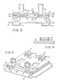
- the side walls 11 and 12 and the top 14 are all formed with sound absorbing insulation 18 enclosed between an outer surface 19 and an inner surface 20 as best seen in Figure 2 of the drawings.
- Each of the side walls 11 and 12 and back wall 13 are secured to the tubular legs 16A, 16B, 16C, and 16 D by a plurality of fasteners 21.
- a door 22 has a main support frame member 23 with a sound isolation panel 24 secured thereto.
- the isolation panel 24 is filled with sound absorbent material 25 as best seen in Figure 2 of the drawings.
- a secondary panel 26 is secured to the opposite side of said main support frame 23 and may also be filled with sound absorbing material.
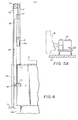
- the main support frame member 23 has right angularly disposed vertical edges 26 which are adapted to receive each, a roller assembly 27 having a roller 27A thereon.
- a vertically extending L-shaped guide track 28 is secured to each of the tubular support legs 16A and 16B extending from the bottom panel 15 to the free end of said legs 16A and 16B.
- a secondary guide track 29 is secured in spaced relation to the guide track 28 on the tubular legs 16A and 16B.
- the rollers 27A are registrable between the guide tracks 28 and secondary guide tracks 29, the latter of which restricts the lateral movement of the door 22 towards and away from the enclosure 10.
- a gasket 30 extends around the perimeter of the enclosure adjacent the opening in sealing relation with the door 22 when in closed position as seen in Figure 6 of the drawings.
- the door 22 has a counter weight assembly 31 comprising a weight 31A with chains 32 extending therefrom to the door 22 over a pair of spaced sprockets 33 on a shaft 34 rotatably secured to the axle support bracket 17.
- a pair of oppositely disposed pneumatic door clamps 35 are secured to the legs 16A and 16B so as to be engagable on the door as seen in Figures 2 and 6 of the drawings.
- a cross support bar 36 extends between the legs 16A and 16B from their free ends and supports a shock absorber 37 therebetween for engagement with the door 22 when in fully opened position.
- the pneumatic door clamps 35 are comprised of a mounting bracket 38 having an apertured free end 38A and a pivot support brace 39 extending outwardly at right angles therefrom.
- the pneumatic piston and cylinder assembly 40 is mounted to the apertured free end 38A with a piston 41 pivotally secured to a clamp arm 42 which is in turn pivoted to the pivot support brace 39 at 43.
- the opposite end of the clamp arm 42 is engagable on the right angular disposed vertical edges 26 upon activation of said piston and cylinder assembly 35 affectively sealing the door 22 against the gasket 30.
- a support fixture 44 can be seen comprising an apertured flat base member 45 with a variety of vertically upstanding work piece engagement brackets 46 and a pair of pneumatic guns 47 secured thereto. It will be evident to those skilled in the art that the placement of the engagement brackets 46 will vary depending on the work piece to be held and that the positioning of the pneumatic guns 47 will also be a matter of choice suited to the particular requirements of the user.
- An isolator support plate 48 is positioned directly under said fixture 44 and has a pair of oppositely disposed inverted U-shaped brackets 49 extending longitudinally along each edge.
- Base member engagement members 50 extend from said brackets 49 stabilizing the fixture 44 which is supported in spaced relation to said isolation plate 48 by a number of isolation members 51.
- Each of said isolation members 51 is comprised of a multiple layered configuration having an inflatable isolation bag 51A positioned between two supporting members 51B and 51C.
- the isolation support plate 48 has a number of widely spaced support feet 52 which in turn are registrable within an equal number of locator wells 53 having an inner diameter greater than that of said support feet 52 and which are located on the bottom panel 15 with a resilient rubberized pad 54 within each of the locator wells as best seen in Figure 4 of the drawings.
- the bottom panel 15 has a pair-of oppositely disposed U-shaped members 55 registrable with a fork lift (not shown) for transport of the casting decoring device.
- a control box 56 can be seen secured to the side wall 12 with a plurality of supply lines 57 extending therefrom and communicating with the door clamps 35, the isolation bags 51A, the pneumatic guns 47 via fittings 47A and an on-off switch 58.
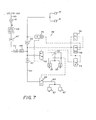
- a control system 59 can be seen having a supply pressure inlet line 60 with a main system control valve 61, a plurality of in line filters 62, 63 and 64 and regulators 65, 66, and 67 to reduce the line pressure and condition the control fluid as will be well understood by those skilled in the art.
- a pilot control switch 68 on the inlet line 60 controls the pneumatic guns 47 via a supply line 69 while a secondary pilot control switch 70 controls the door clamps 35 via supply lines 71 and 72.
- the on-off switch 58, a system timer 73, a limit valve 74 and a shuttle valve 75 complete the major control components of the pilot control of the system.
- the door 22 is raised by a handle H and the fixture 44 with the work pieces W positioned thereon is set into the enclosure.10.
- the supply lines 57 are connected as hereinbefore described and the door 22 is closed.
- the pilot control system acuates the door clamps 35 via the secondary pilot control switch 70 which in turn activates the pneumatic guns 47 via the pilot control switch 68.
- the timer 73 controls the overall cycle of the system which is predetermined based on the number and type of workpieces W on the fixture 44.
- the on-off switch 58 gives the operator overall control of the pilot control system as will be evident from the above description.
- a disposal chute 76 can be seen in broken lines in which the sand and binder freed from the work piece passes out of the casting decoring device as it falls through the aperture in the base panel 15.
Landscapes
- Engineering & Computer Science (AREA)
- Mechanical Engineering (AREA)
- Casting Devices For Molds (AREA)
- Purses, Travelling Bags, Baskets, Or Suitcases (AREA)
- Casings For Electric Apparatus (AREA)
Applications Claiming Priority (2)
| Application Number | Priority Date | Filing Date | Title |
|---|---|---|---|
| US06/623,028 US4577671A (en) | 1982-08-09 | 1984-06-21 | Casting decoring device |
| US623028 | 1984-06-21 |
Publications (1)
| Publication Number | Publication Date |
|---|---|
| EP0165892A1 true EP0165892A1 (fr) | 1985-12-27 |
Family
ID=24496482
Family Applications (1)
| Application Number | Title | Priority Date | Filing Date |
|---|---|---|---|
| EP85630096A Withdrawn EP0165892A1 (fr) | 1984-06-21 | 1985-06-20 | Dispositif pour enlever des noyaux des pièces coulées |
Country Status (3)
| Country | Link |
|---|---|
| US (1) | US4577671A (fr) |
| EP (1) | EP0165892A1 (fr) |
| NO (1) | NO852506L (fr) |
Cited By (1)
| Publication number | Priority date | Publication date | Assignee | Title |
|---|---|---|---|---|
| FR2850305A1 (fr) * | 2003-01-23 | 2004-07-30 | Marcel Massin | Systeme automatise de debourrage et dispositif de debourrage |
Families Citing this family (28)
| Publication number | Priority date | Publication date | Assignee | Title |
|---|---|---|---|---|
| US5354038A (en) * | 1989-09-29 | 1994-10-11 | Consolidated Engineering Company, Inc. | Heat treatment of metal castings and in-furnace sand reclamation |
| US5294094A (en) * | 1989-09-29 | 1994-03-15 | Consolidated Engineering Company | Method and apparatus for heat treating metal castings |
| US5350160A (en) * | 1989-09-29 | 1994-09-27 | Consolidated Engineering Company | Method and apparatus for heat treating metal castings |
| JPH07112621B2 (ja) * | 1990-11-07 | 1995-12-06 | ドーラー・ジヤービス・リミテツド・パートナーシツプ | 鋳造品中の砂中子を振動により崩壊、除去する装置 |
| WO1997030805A1 (fr) * | 1996-02-23 | 1997-08-28 | Consolidated Engineering Company, Inc. | Systeme et procede de recuperation de sable |
| US5924473A (en) * | 1996-12-20 | 1999-07-20 | General Kinematics Corporation | Vibratory sand reclamation system |
| US5901775A (en) * | 1996-12-20 | 1999-05-11 | General Kinematics Corporation | Two-stage heat treating decoring and sand reclamation system |
| US6453982B1 (en) | 1996-12-20 | 2002-09-24 | General Kinematics Corporation | Sand cleaning apparatus |
| US5738162A (en) * | 1997-02-20 | 1998-04-14 | Consolidated Engineering Company, Inc. | Terraced fluidized bed |
| DE19803726B4 (de) * | 1998-01-30 | 2007-12-27 | Heidelberger Druckmaschinen Ag | Druckwerk mit einem Druckwerksschutz und einer verstellbaren Aufhängung für den Druckwerksschutz |
| US6286805B1 (en) * | 1998-07-01 | 2001-09-11 | Clear Vision Laser Centers, Inc. | Apparatus and method for transporting equipment between buildings |
| US6217317B1 (en) | 1998-12-15 | 2001-04-17 | Consolidated Engineering Company, Inc. | Combination conduction/convection furnace |
| US6336809B1 (en) | 1998-12-15 | 2002-01-08 | Consolidated Engineering Company, Inc. | Combination conduction/convection furnace |
| US7275582B2 (en) * | 1999-07-29 | 2007-10-02 | Consolidated Engineering Company, Inc. | Methods and apparatus for heat treatment and sand removal for castings |
| US6672367B2 (en) | 1999-07-29 | 2004-01-06 | Consolidated Engineering Company, Inc. | Methods and apparatus for heat treatment and sand removal for castings |
| US6910522B2 (en) * | 1999-07-29 | 2005-06-28 | Consolidated Engineering Company, Inc. | Methods and apparatus for heat treatment and sand removal for castings |
| US6622775B2 (en) | 2000-05-10 | 2003-09-23 | Consolidated Engineering Company, Inc. | Method and apparatus for assisting removal of sand moldings from castings |
| JP2004523362A (ja) * | 2001-02-02 | 2004-08-05 | コンソリデイテッド エンジニアリング カンパニー, インコーポレイテッド | 一体型金属プロセシング設備 |
| US7338629B2 (en) * | 2001-02-02 | 2008-03-04 | Consolidated Engineering Company, Inc. | Integrated metal processing facility |
| EP1526938B1 (fr) * | 2002-07-11 | 2012-02-29 | Consolidated Engineering Company, Inc. | Procede facilitant le demoulage des objets moules de leurs moules en sable |
| US6901990B2 (en) * | 2002-07-18 | 2005-06-07 | Consolidated Engineering Company, Inc. | Method and system for processing castings |
| US7252134B2 (en) * | 2004-06-28 | 2007-08-07 | Consolidated Engineering Company, Inc. | Method and apparatus for removal of flashing and blockages from a casting |
| US20060054294A1 (en) * | 2004-09-15 | 2006-03-16 | Crafton Scott P | Short cycle casting processing |
| US20060103059A1 (en) * | 2004-10-29 | 2006-05-18 | Crafton Scott P | High pressure heat treatment system |
| WO2007147091A2 (fr) * | 2006-06-15 | 2007-12-21 | Consolidated Engineering Company, Inc. | Procédés et système pour fabriquer des piÈces coulÉes en utilisant un système flexible de fabrication automatisÉe |
| WO2008121671A2 (fr) * | 2007-03-29 | 2008-10-09 | Consolidated Engineering Company, Inc. | Système de traitement thermique vertical |
| CN102950258A (zh) * | 2011-08-27 | 2013-03-06 | 泰州鑫宇精密铸造有限公司 | 封闭式气动振壳机 |
| AU2016254028B2 (en) | 2015-04-28 | 2019-10-17 | Consolidated Engineering Company, Inc. | System and method for heat treating aluminum alloy castings |
Citations (2)
| Publication number | Priority date | Publication date | Assignee | Title |
|---|---|---|---|---|
| GB2067938A (en) * | 1980-01-17 | 1981-08-05 | Stoner & Saunders Andover Ltd | A casting-core knockout machine |
| DE3013720A1 (de) * | 1980-04-10 | 1981-10-15 | Elmar Michael Dipl.-Ing. 4150 Krefeld Veltrup | Vorrichtung zum entkernen von gussteilen mit hochdruckwasserstrahlen |
Family Cites Families (13)
| Publication number | Priority date | Publication date | Assignee | Title |
|---|---|---|---|---|
| US1966571A (en) * | 1930-07-19 | 1934-07-17 | Colt S Mfg Co | Wet sand blast apparatus |
| US1870120A (en) * | 1930-12-27 | 1932-08-02 | James T Humes | Sound muffling device for typewriters and other machines |
| US2008741A (en) * | 1932-02-03 | 1935-07-23 | James R Allan | Seal for closures |
| US2179495A (en) * | 1938-12-29 | 1939-11-14 | Alva B Court | Door and hatch closure |
| US2686991A (en) * | 1950-11-07 | 1954-08-24 | Pangborn Corp | Blast cleaning apparatus and method |
| DK116700A (fr) * | 1963-07-12 | |||
| US3298138A (en) * | 1964-02-24 | 1967-01-17 | Pangborn Corp | Apparatus for deflashing molded resilient pieces |
| US3406997A (en) * | 1966-09-22 | 1968-10-22 | Riggs & Lombard Inc | Pressure door locking mechanism |
| GB1425924A (en) * | 1972-05-18 | 1976-02-25 | Russel Finex | Vibratory apparatus |
| SU526446A1 (ru) * | 1975-01-23 | 1976-08-30 | Предприятие П/Я Р-6375 | Провальна решетка |
| US4153227A (en) * | 1975-11-28 | 1979-05-08 | Gamaunt Roger L | Fluid self-centering vibration and shock mount |
| US4185681A (en) * | 1978-06-22 | 1980-01-29 | Conveyersmith, Inc. | Ceramic knock-off apparatus for removing ceramic from investment casting molds |
| US4206800A (en) * | 1979-02-05 | 1980-06-10 | General Motors Corporation | Rotary acoustic sand-core shakeout |
-
1984
- 1984-06-21 US US06/623,028 patent/US4577671A/en not_active Expired - Fee Related
-
1985
- 1985-06-20 EP EP85630096A patent/EP0165892A1/fr not_active Withdrawn
- 1985-06-21 NO NO852506A patent/NO852506L/no unknown
Patent Citations (2)
| Publication number | Priority date | Publication date | Assignee | Title |
|---|---|---|---|---|
| GB2067938A (en) * | 1980-01-17 | 1981-08-05 | Stoner & Saunders Andover Ltd | A casting-core knockout machine |
| DE3013720A1 (de) * | 1980-04-10 | 1981-10-15 | Elmar Michael Dipl.-Ing. 4150 Krefeld Veltrup | Vorrichtung zum entkernen von gussteilen mit hochdruckwasserstrahlen |
Cited By (2)
| Publication number | Priority date | Publication date | Assignee | Title |
|---|---|---|---|---|
| FR2850305A1 (fr) * | 2003-01-23 | 2004-07-30 | Marcel Massin | Systeme automatise de debourrage et dispositif de debourrage |
| CN100349676C (zh) * | 2003-01-23 | 2007-11-21 | 马森科技股份公司 | 自动除芯系统和除芯装置 |
Also Published As
| Publication number | Publication date |
|---|---|
| NO852506L (no) | 1986-02-12 |
| US4577671A (en) | 1986-03-25 |
Similar Documents
| Publication | Publication Date | Title |
|---|---|---|
| US4577671A (en) | Casting decoring device | |
| US2973606A (en) | Machine for precision finishing of parts by controlled vibration | |
| US4585019A (en) | Heavy duty air filter reconditioning system | |
| CN110405396A (zh) | 一种机械加工用自动化焊接平台 | |
| US2669810A (en) | Method and apparatus for graining lithographic plates | |
| JP5424124B2 (ja) | ターンテーブル装置及び半自動減圧鋳型造型鋳造ライン | |
| US3906756A (en) | Drapery and sheet material cleaning machine | |
| US3774888A (en) | Vibratory apparatus | |
| JPH11507599A (ja) | 壁面清掃用ブラスト装置 | |
| US1062248A (en) | Suction-hood for abrading-tools. | |
| AU4992793A (en) | Dry abrasive belt cleaner | |
| US4829714A (en) | Devurring and cleaning machine and process | |
| CN208743118U (zh) | 一种新型医疗器械清洗装置 | |
| US2482034A (en) | Marking device | |
| CN105170953B (zh) | 一种自动环保振壳机 | |
| CN208116245U (zh) | 一种用于载具的清漂一体机 | |
| US3831322A (en) | Continuous feed vibratory finishing machine with discharge rate controlled by operation of tub discharge closure | |
| US1643175A (en) | Sand-blast apparatus | |
| US5657813A (en) | Core blowing machine blowing plate exchanging and cleaning system | |
| JPH0675119B2 (ja) | 原子力施設における床の洗浄・拭取除染機 | |
| CN220971894U (zh) | 一种表面处理装置 | |
| US3959932A (en) | Finishing system with cyclically operable closure control | |
| CN112323081A (zh) | 一种金属业用铁块化学除锈装置 | |
| US1637196A (en) | Sand-blasting machine | |
| DE69000598T2 (de) | Einrichtung zum putzen von gusstuecken. |
Legal Events
| Date | Code | Title | Description |
|---|---|---|---|
| PUAI | Public reference made under article 153(3) epc to a published international application that has entered the european phase |
Free format text: ORIGINAL CODE: 0009012 |
|
| AK | Designated contracting states |
Designated state(s): DE FR GB IT SE |
|
| 17P | Request for examination filed |
Effective date: 19860625 |
|
| 17Q | First examination report despatched |
Effective date: 19870319 |
|
| STAA | Information on the status of an ep patent application or granted ep patent |
Free format text: STATUS: THE APPLICATION IS DEEMED TO BE WITHDRAWN |
|
| 18D | Application deemed to be withdrawn |
Effective date: 19870730 |
|
| RIN1 | Information on inventor provided before grant (corrected) |
Inventor name: STEPHAN, MARK |