EP0166074A2 - Aufschlagbetätigtes Kontaktelement für Geschoss - Google Patents
Aufschlagbetätigtes Kontaktelement für Geschoss Download PDFInfo
- Publication number
- EP0166074A2 EP0166074A2 EP85101471A EP85101471A EP0166074A2 EP 0166074 A2 EP0166074 A2 EP 0166074A2 EP 85101471 A EP85101471 A EP 85101471A EP 85101471 A EP85101471 A EP 85101471A EP 0166074 A2 EP0166074 A2 EP 0166074A2
- Authority
- EP
- European Patent Office
- Prior art keywords
- projectile
- conductors
- sensor
- circuit
- impact
- Prior art date
- Legal status (The legal status is an assumption and is not a legal conclusion. Google has not performed a legal analysis and makes no representation as to the accuracy of the status listed.)
- Withdrawn
Links
- 239000004020 conductor Substances 0.000 claims abstract description 29
- 230000000149 penetrating effect Effects 0.000 claims abstract 2
- 239000011810 insulating material Substances 0.000 claims description 4
- 239000012777 electrically insulating material Substances 0.000 claims description 2
- 239000002985 plastic film Substances 0.000 abstract 2
- 229920006255 plastic film Polymers 0.000 abstract 2
- 239000000853 adhesive Substances 0.000 description 2
- 230000001070 adhesive effect Effects 0.000 description 2
- 239000000463 material Substances 0.000 description 2
- RYGMFSIKBFXOCR-UHFFFAOYSA-N Copper Chemical compound [Cu] RYGMFSIKBFXOCR-UHFFFAOYSA-N 0.000 description 1
- 239000004642 Polyimide Substances 0.000 description 1
- 229910052802 copper Inorganic materials 0.000 description 1
- 239000010949 copper Substances 0.000 description 1
- 238000011161 development Methods 0.000 description 1
- 230000018109 developmental process Effects 0.000 description 1
- 239000002360 explosive Substances 0.000 description 1
- 239000011888 foil Substances 0.000 description 1
- 239000004033 plastic Substances 0.000 description 1
- 229920006267 polyester film Polymers 0.000 description 1
- 229920001721 polyimide Polymers 0.000 description 1
- 230000037452 priming Effects 0.000 description 1
Images
Classifications
-
- H—ELECTRICITY
- H01—ELECTRIC ELEMENTS
- H01H—ELECTRIC SWITCHES; RELAYS; SELECTORS; EMERGENCY PROTECTIVE DEVICES
- H01H35/00—Switches operated by change of a physical condition
- H01H35/14—Switches operated by change of acceleration, e.g. by shock or vibration, inertia switch
- H01H35/146—Switches operated by change of acceleration, e.g. by shock or vibration, inertia switch operated by plastic deformation or rupture of structurally associated elements
-
- F—MECHANICAL ENGINEERING; LIGHTING; HEATING; WEAPONS; BLASTING
- F42—AMMUNITION; BLASTING
- F42C—AMMUNITION FUZES; ARMING OR SAFETY MEANS THEREFOR
- F42C19/00—Details of fuzes
- F42C19/06—Electric contact parts specially adapted for use with electric fuzes
- F42C19/07—Nose-contacts for projectiles or missiles
Definitions
- the present invention relates to an impact sensor for a projectile, comprising a source of power with an open circuit, which is so arranged as to be closed as the result of a deformation of the projectile at an impact by the projectile on a target, and a sensing element for the purpose of sensing said closing of the circuit.
- the object of the present invention is, therefore, to propose an impact sensor of the type described by way of introduction, in which the circuit is insensitive to the surrounding environment, and in which the risk of unintentional short-circuiting is eliminated.
- This object is achieved by the impact sensor in accordance with the invention having being given the characteristic features indicated in Claim 1.
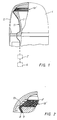
- Figure 1 shows a cross-section and a sectioned view of the nose part of a projectile fitted with an impact sensor in accordance with the invention.
- Figure 2 shows part of Figure 1 on an enlarged scale.
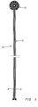
- Figure 3 shows a modified embodiment of a flexible conductor which forms part of the sensor in accordance with Figure 1.
- Figure 1 shows a nose part of a projectile 1, of which the rest is not shown.
- the reference 2 is used to denote the casing of the projectile.
- the nose part of the projectile exhibits a centrally positioned, essentially cylindrical cap 3, not described here in any greater detail, which between itself and the casing 2 of the projectile forms an air gap 4; see Figure 2.
- the cap 3 exhibits at its front end an annular step 5, which has the form of the generated surface of a truncated cone.
- the projectile 1 is fitted with an impact sensor comprising a source of power 6, represented only schematically, and a sensing element, also represented only schematically, in the form of a fuse pipe 7.
- the source of power 6 may, for example, have the form of a battery capable of being charged by the acceleeration of the projectile, or may be a piezoelectric generator. Since both the source of power 6 and the fuse pipe 7 may be of an arbitrary, conventional nature, they are neither shown nor described here in any greater detail.
- the source of power 6 and the fuse pipe 7 exhibit an open circuit in the form of two extremely thin, strip-shaped, electrical copper conductors 8 and 9.
- the conductors are embedded entirely in an electrically insulating material, for example in the form of a polyimide or polyester film, so as to form a so-called flexible conductor 10.
- the conductors 8 and 9 thus have the form of a thin circuit pattern etched into the plastic foil.
- the flexible conductor 10 is generally of the form shown in Figure 3, that is to say with an elongated part 11, in which the two conductors 8 and 9 run parallel with each other, and a sensor part 12, in which the two conductors 8 and 9 are routed adjacent to each other in pairs according to a pre-determined pattern.
- the sensor part in Figures 1 and 2 has a rather different appearance than it does in Figure 3, where it is denoted by the reference 12'.
- the sensor part 12' has the same form as the step 5, and is attached to the latter, for example by means of an adhesive or with the help of tape.
- the elongated part 11 follows an appropriate inner profile inside the projectile, and is also attached to the latter by means of an adhesive or with the help of tape.
- the circuit pattern in the sensor part 12 and 12' can have many different appearances, with those illustrated being only examples of conceivable patterns.
- the two strip-shaped conductors 8 and 9 lie in the same plane. In an alternative embodiment, not shown here, they may lie one on top of the other, separated from each other by means of a layer of the aforementioned insulating material.
- the casing 2 of the projectile exhibits,directly in line with the step 5, a stair-shaped reducing diameter intended to form a number (being three in the example shown) of annular, metallic edges 13, the sharp part of which is situated in the air gap 4 at a distance of up to about 0.5 - 1 mm from the step 5.
- the edges 13 are best formed at the same time as the casing of the projectile is being manufactured.
- the function of the impact sensor is as follows.
- the casing of the projectile When the projectile strikes a target, the casing of the projectile is deformed in such a way that the edges 13 penetrate the insulating material in the flexible conductor 10 and make a contact between the conductors 8 and 9, causing a current to flow from the source of power 6 to the fuse pipe 7.
- a desired function may be actuated in the projectile, for example the priming of an explosive charge (not shown).
- the edge 13 will first cut through one of the conductors, and then through the interjacent insulating layer until the edge reaches the second conductor, causing the circuit to be closed.
- edges 13 and the conductors 8, 9 are also conceivable within the scope of the invention to cause the edges 13 and the conductors 8, 9 to exchange places, that is to say to attach the insulated conductors to the inside of the casing of the projectile, and the edges to some component part of the projectile within the casing of the projectile.
- the sensor part 12 or 12' of the flexible conductor can be arranged in the projectile at any point at which it is wished to provide an impact sensing function. It is also obvious that the edges may have a form other than that shown.
Landscapes
- Engineering & Computer Science (AREA)
- General Engineering & Computer Science (AREA)
- Switches Operated By Changes In Physical Conditions (AREA)
- Burglar Alarm Systems (AREA)
- Discharge Of Articles From Conveyors (AREA)
- Excavating Of Shafts Or Tunnels (AREA)
- Radar Systems Or Details Thereof (AREA)
- Geophysics And Detection Of Objects (AREA)
- Spark Plugs (AREA)
- Fuses (AREA)
Applications Claiming Priority (2)
| Application Number | Priority Date | Filing Date | Title |
|---|---|---|---|
| SE8401289 | 1984-03-08 | ||
| SE8401289A SE437192B (sv) | 1984-03-08 | 1984-03-08 | Anslagssensor for en projektil |
Publications (2)
| Publication Number | Publication Date |
|---|---|
| EP0166074A2 true EP0166074A2 (de) | 1986-01-02 |
| EP0166074A3 EP0166074A3 (de) | 1986-01-08 |
Family
ID=20355057
Family Applications (1)
| Application Number | Title | Priority Date | Filing Date |
|---|---|---|---|
| EP85101471A Withdrawn EP0166074A3 (de) | 1984-03-08 | 1985-02-12 | Aufschlagbetätigtes Kontaktelement für Geschoss |
Country Status (4)
| Country | Link |
|---|---|
| EP (1) | EP0166074A3 (de) |
| JP (1) | JPS6177217A (de) |
| NO (1) | NO850840L (de) |
| SE (1) | SE437192B (de) |
Cited By (3)
| Publication number | Priority date | Publication date | Assignee | Title |
|---|---|---|---|---|
| US4913057A (en) * | 1987-04-03 | 1990-04-03 | Aktiebolaget Bofors | Armor piercing shell |
| US8297193B1 (en) * | 2011-07-08 | 2012-10-30 | Foster-Miller, Inc. | Surrogate RPG |
| DE102017208920A1 (de) | 2017-05-26 | 2018-11-29 | Lithium Energy and Power GmbH & Co. KG | Sensoranordnung und Batteriesystem aufweisend eine derartige Sensoranordnung |
Family Cites Families (4)
| Publication number | Priority date | Publication date | Assignee | Title |
|---|---|---|---|---|
| FR2070389A5 (de) * | 1969-12-03 | 1971-09-10 | Serat | |
| FR2157152A5 (en) * | 1971-10-20 | 1973-06-01 | Serat | Nose cone contactor for projectiles - with high degree of sensitivity |
| US4412114A (en) * | 1982-03-03 | 1983-10-25 | John Arbeeny | Electrical switch |
| FR2528764A1 (fr) * | 1982-06-18 | 1983-12-23 | Lincrusta | Procede de fabrication d'ogives pour munitions et ogives obtenues par ce procede |
-
1984
- 1984-03-08 SE SE8401289A patent/SE437192B/sv not_active IP Right Cessation
-
1985
- 1985-02-12 EP EP85101471A patent/EP0166074A3/de not_active Withdrawn
- 1985-03-01 NO NO850840A patent/NO850840L/no unknown
- 1985-03-08 JP JP4732985A patent/JPS6177217A/ja active Pending
Cited By (4)
| Publication number | Priority date | Publication date | Assignee | Title |
|---|---|---|---|---|
| US4913057A (en) * | 1987-04-03 | 1990-04-03 | Aktiebolaget Bofors | Armor piercing shell |
| US8297193B1 (en) * | 2011-07-08 | 2012-10-30 | Foster-Miller, Inc. | Surrogate RPG |
| WO2013009348A1 (en) * | 2011-07-08 | 2013-01-17 | Foster-Miller, Inc. | Surrogate rpg |
| DE102017208920A1 (de) | 2017-05-26 | 2018-11-29 | Lithium Energy and Power GmbH & Co. KG | Sensoranordnung und Batteriesystem aufweisend eine derartige Sensoranordnung |
Also Published As
| Publication number | Publication date |
|---|---|
| SE8401289D0 (sv) | 1984-03-08 |
| EP0166074A3 (de) | 1986-01-08 |
| JPS6177217A (ja) | 1986-04-19 |
| SE437192B (sv) | 1985-02-11 |
| NO850840L (no) | 1985-09-09 |
Similar Documents
| Publication | Publication Date | Title |
|---|---|---|
| RU2046277C1 (ru) | Воспламенительное устройство для электродетонатора с замедлением и по меньшей мере одним основным зарядом в корпусе детонатора | |
| US4109295A (en) | Solderless circuit board component | |
| US4683360A (en) | Membrane switch combined with electroluminescent lamp panel | |
| GB2074375B (en) | Ptc elements | |
| FR2800865B1 (fr) | Initiateur pyrotechnique a filament photograve protege contre les decharges electrostatiques | |
| HK82589A (en) | Circuit protection devices | |
| SE434191B (sv) | Eltenddon, foretredesvis for artilleriammunition | |
| HK94286A (en) | Corrosion protection system | |
| EP0166074A2 (de) | Aufschlagbetätigtes Kontaktelement für Geschoss | |
| WO2000026627A8 (en) | Tactile pressure sensor | |
| CA2279060A1 (en) | Electronic missile location | |
| US20130284043A1 (en) | Silver bridge element slapper detonator | |
| EP1365481A3 (de) | Leiterplattenrandverbinder und Karte | |
| US4063513A (en) | Target sensing device | |
| US4648320A (en) | Detonator triggering device | |
| SE452675B (sv) | Anordning i form av en elektrisk sekring, som er kombinerad med ett anslutningsdon | |
| US5293004A (en) | Printed circuit board having an electromagnetic shielding layer | |
| EP0864844A3 (de) | Brückenzünder für Explosivstoffe und Verfahren zum Herstellen eines solchen Zünders | |
| KR850004344A (ko) | 음극선관의 내장저항기 | |
| WO2005045997A3 (en) | An electrical circuit assembly with improved shock resistance | |
| US4033657A (en) | Buss barr | |
| US4231041A (en) | Electrically conducting lead termination apparatus for a thin film antenna | |
| KR101430581B1 (ko) | 연성회로기판과 절연시트가 적용된 충격감지장치 | |
| EP0388312A3 (de) | Chipträger mit verbesserter Flexibilität | |
| CN213812677U (zh) | 柔性压力传感器 |
Legal Events
| Date | Code | Title | Description |
|---|---|---|---|
| PUAI | Public reference made under article 153(3) epc to a published international application that has entered the european phase |
Free format text: ORIGINAL CODE: 0009012 |
|
| PUAL | Search report despatched |
Free format text: ORIGINAL CODE: 0009013 |
|
| 17P | Request for examination filed |
Effective date: 19850312 |
|
| AK | Designated contracting states |
Designated state(s): BE CH DE FR GB IT LI NL |
|
| AK | Designated contracting states |
Designated state(s): BE CH DE FR GB IT LI NL |
|
| 17Q | First examination report despatched |
Effective date: 19870331 |
|
| STAA | Information on the status of an ep patent application or granted ep patent |
Free format text: STATUS: THE APPLICATION IS DEEMED TO BE WITHDRAWN |
|
| 18D | Application deemed to be withdrawn |
Effective date: 19870811 |
|
| RIN1 | Information on inventor provided before grant (corrected) |
Inventor name: SUNDVALL, KENNETH |