EP0166084A1 - Carburateur pour gaz de pétrole liquéfié - Google Patents
Carburateur pour gaz de pétrole liquéfié Download PDFInfo
- Publication number
- EP0166084A1 EP0166084A1 EP85103493A EP85103493A EP0166084A1 EP 0166084 A1 EP0166084 A1 EP 0166084A1 EP 85103493 A EP85103493 A EP 85103493A EP 85103493 A EP85103493 A EP 85103493A EP 0166084 A1 EP0166084 A1 EP 0166084A1
- Authority
- EP
- European Patent Office
- Prior art keywords
- pressure
- engine
- fuel
- petroleum gas
- liquified petroleum
- Prior art date
- Legal status (The legal status is an assumption and is not a legal conclusion. Google has not performed a legal analysis and makes no representation as to the accuracy of the status listed.)
- Withdrawn
Links
- 239000003209 petroleum derivative Substances 0.000 title claims abstract description 20
- 239000000446 fuel Substances 0.000 claims abstract description 113
- 239000007788 liquid Substances 0.000 claims abstract description 15
- 230000001360 synchronised effect Effects 0.000 claims abstract description 4
- 239000002826 coolant Substances 0.000 claims description 23
- 238000002485 combustion reaction Methods 0.000 claims description 6
- 238000011144 upstream manufacturing Methods 0.000 claims description 5
- 238000007599 discharging Methods 0.000 claims description 3
- 230000001105 regulatory effect Effects 0.000 claims description 3
- 238000000034 method Methods 0.000 claims 3
- 230000001276 controlling effect Effects 0.000 claims 2
- 238000001816 cooling Methods 0.000 claims 1
- 239000012530 fluid Substances 0.000 claims 1
- 230000008016 vaporization Effects 0.000 claims 1
- 230000003028 elevating effect Effects 0.000 abstract 1
- 239000003570 air Substances 0.000 description 48
- 239000003915 liquefied petroleum gas Substances 0.000 description 12
- XLYOFNOQVPJJNP-UHFFFAOYSA-N water Substances O XLYOFNOQVPJJNP-UHFFFAOYSA-N 0.000 description 6
- ATUOYWHBWRKTHZ-UHFFFAOYSA-N Propane Chemical compound CCC ATUOYWHBWRKTHZ-UHFFFAOYSA-N 0.000 description 3
- 230000001133 acceleration Effects 0.000 description 3
- 238000010586 diagram Methods 0.000 description 3
- 239000007789 gas Substances 0.000 description 3
- OFBQJSOFQDEBGM-UHFFFAOYSA-N n-pentane Natural products CCCCC OFBQJSOFQDEBGM-UHFFFAOYSA-N 0.000 description 3
- 238000009835 boiling Methods 0.000 description 2
- 239000002828 fuel tank Substances 0.000 description 2
- 229920006395 saturated elastomer Polymers 0.000 description 2
- 239000006200 vaporizer Substances 0.000 description 2
- 239000012080 ambient air Substances 0.000 description 1
- 230000004888 barrier function Effects 0.000 description 1
- 239000001273 butane Substances 0.000 description 1
- 238000010276 construction Methods 0.000 description 1
- 239000003502 gasoline Substances 0.000 description 1
- 238000010438 heat treatment Methods 0.000 description 1
- 239000000203 mixture Substances 0.000 description 1
- IJDNQMDRQITEOD-UHFFFAOYSA-N n-butane Chemical compound CCCC IJDNQMDRQITEOD-UHFFFAOYSA-N 0.000 description 1
- 239000001294 propane Substances 0.000 description 1
Images

Classifications
-
- F—MECHANICAL ENGINEERING; LIGHTING; HEATING; WEAPONS; BLASTING
- F02—COMBUSTION ENGINES; HOT-GAS OR COMBUSTION-PRODUCT ENGINE PLANTS
- F02M—SUPPLYING COMBUSTION ENGINES IN GENERAL WITH COMBUSTIBLE MIXTURES OR CONSTITUENTS THEREOF
- F02M21/00—Apparatus for supplying engines with non-liquid fuels, e.g. gaseous fuels stored in liquid form
- F02M21/02—Apparatus for supplying engines with non-liquid fuels, e.g. gaseous fuels stored in liquid form for gaseous fuels
- F02M21/0218—Details on the gaseous fuel supply system, e.g. tanks, valves, pipes, pumps, rails, injectors or mixers
- F02M21/023—Valves; Pressure or flow regulators in the fuel supply or return system
- F02M21/0239—Pressure or flow regulators therefor
-
- F—MECHANICAL ENGINEERING; LIGHTING; HEATING; WEAPONS; BLASTING
- F02—COMBUSTION ENGINES; HOT-GAS OR COMBUSTION-PRODUCT ENGINE PLANTS
- F02B—INTERNAL-COMBUSTION PISTON ENGINES; COMBUSTION ENGINES IN GENERAL
- F02B43/00—Engines characterised by operating on gaseous fuels; Plants including such engines
-
- F—MECHANICAL ENGINEERING; LIGHTING; HEATING; WEAPONS; BLASTING
- F02—COMBUSTION ENGINES; HOT-GAS OR COMBUSTION-PRODUCT ENGINE PLANTS
- F02M—SUPPLYING COMBUSTION ENGINES IN GENERAL WITH COMBUSTIBLE MIXTURES OR CONSTITUENTS THEREOF
- F02M21/00—Apparatus for supplying engines with non-liquid fuels, e.g. gaseous fuels stored in liquid form
- F02M21/02—Apparatus for supplying engines with non-liquid fuels, e.g. gaseous fuels stored in liquid form for gaseous fuels
- F02M21/0203—Apparatus for supplying engines with non-liquid fuels, e.g. gaseous fuels stored in liquid form for gaseous fuels characterised by the type of gaseous fuel
- F02M21/0209—Hydrocarbon fuels, e.g. methane or acetylene
- F02M21/0212—Hydrocarbon fuels, e.g. methane or acetylene comprising at least 3 C-Atoms, e.g. liquefied petroleum gas [LPG], propane or butane
-
- F—MECHANICAL ENGINEERING; LIGHTING; HEATING; WEAPONS; BLASTING
- F02—COMBUSTION ENGINES; HOT-GAS OR COMBUSTION-PRODUCT ENGINE PLANTS
- F02M—SUPPLYING COMBUSTION ENGINES IN GENERAL WITH COMBUSTIBLE MIXTURES OR CONSTITUENTS THEREOF
- F02M21/00—Apparatus for supplying engines with non-liquid fuels, e.g. gaseous fuels stored in liquid form
- F02M21/02—Apparatus for supplying engines with non-liquid fuels, e.g. gaseous fuels stored in liquid form for gaseous fuels
- F02M21/04—Gas-air mixing apparatus
-
- F—MECHANICAL ENGINEERING; LIGHTING; HEATING; WEAPONS; BLASTING
- F02—COMBUSTION ENGINES; HOT-GAS OR COMBUSTION-PRODUCT ENGINE PLANTS
- F02M—SUPPLYING COMBUSTION ENGINES IN GENERAL WITH COMBUSTIBLE MIXTURES OR CONSTITUENTS THEREOF
- F02M21/00—Apparatus for supplying engines with non-liquid fuels, e.g. gaseous fuels stored in liquid form
- F02M21/02—Apparatus for supplying engines with non-liquid fuels, e.g. gaseous fuels stored in liquid form for gaseous fuels
- F02M21/06—Apparatus for de-liquefying, e.g. by heating
-
- Y—GENERAL TAGGING OF NEW TECHNOLOGICAL DEVELOPMENTS; GENERAL TAGGING OF CROSS-SECTIONAL TECHNOLOGIES SPANNING OVER SEVERAL SECTIONS OF THE IPC; TECHNICAL SUBJECTS COVERED BY FORMER USPC CROSS-REFERENCE ART COLLECTIONS [XRACs] AND DIGESTS
- Y02—TECHNOLOGIES OR APPLICATIONS FOR MITIGATION OR ADAPTATION AGAINST CLIMATE CHANGE
- Y02T—CLIMATE CHANGE MITIGATION TECHNOLOGIES RELATED TO TRANSPORTATION
- Y02T10/00—Road transport of goods or passengers
- Y02T10/10—Internal combustion engine [ICE] based vehicles
- Y02T10/30—Use of alternative fuels, e.g. biofuels
Definitions
- This invention relates to fuel charge forming devices for internal combustion engines and in particular to an air valve carburetor for Liquified Petroleum Gas or similar fuels.
- United States Patent 3,960,126 issued on June 1, 1976 to Kazuo Shinoda and entitled "Pressure Regulator of Liquefied-Gas Fuel System For Internal Combustion Engines" describes a pressure regulator to be used to change air fuel ratios between two valves in accordance with the engine load.
- the system in which the regulator is used has an air valve responding to air intake to the engine to control a fuel metering valve.
- LPG Liquefied Petroleum Gas
- a fuel tank in an equilibrium state wherein the fuel is liquid. This state is at a high pressure which is a function of the ambient temperature of the fuel tank.
- Fuel is transferred through a fuel line from the tank to inlet tube of the engine through a first pressure regulator which reduces the fuel pressure to a level reducing the boiling point of the fuel to a temperature that is lower than any ambient "temperature that the sytem will experience.
- a temperature is minus forty degrees Centigrade wherein the pressure is .35Kg/cm or 5psig.
- the fuel is still liquid and is passed through a heat exchanger or vaporizer to convert the fuel to a vapor.
- the vaporized fuel is supplied to a second pressure regulator to reduce the fuel pressure to a level slightly below ambient.
- the reduced pressure fuel is then metered into the inlet tube of the engine.
- the structure of the preferred embodiment is a carburetor wherein the first pressure regulator, the heat exchanger, the second pressure regulator and the metering valve are integral with the heat exchanger and mounted contiguous with the intake manifold.
- the system is a mono-fuel system able to meter the various LPG fuels and does not meter conventional fuels for internal combustion engines.
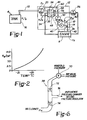
- Figure 1 a schematic diagram of the present invention.
- LPG includes butane, propane, pentane, etc.
- the fuel must be mixed with a proper amount of air in order to operate the engine 8.
- the air is metered by a first metering valve 10 which responds to the pressure on either side thereof to provide the proper amount of air.
- the downstream pressure is controlled by a throttle valve or blade 14 operated in response to the desired engine requirements.
- the fuel is stored as a liquid in a sealed tank 16 at a pressure P1 at a temperature T a .
- the temperature is typically the ambient temperature of the environment wherein the fuel is stored.
- the fuel is removed from the tank 16 by means of a fuel line 18 to the carburetor 12 mounted on the engine 8.
- the fuel enters the carburetor 12 at a first pressure regulator 20 which is integral with the carburetor 12.
- the input pressure to the first pressure regulator 12 is P 2 which is less than P 1 by the pressure drops in the fuel line 18 from the tank 16 to the first pressure regulator 20.
- the fuel pressure has reduced to a second pressure P 3 at a temperature T 3 .
- the pressure P3 in the preferred embodiment is .35Kg/cm which in the English system is 5 psig. Since the fuel is in equilibrium the temperature T 3 is approximately -40°C.
- the temperature of the fuel is a temperature which is lower than the environment in which the engine 8 may typically be found. As will be shown, it is necessary that the temperature of the fuel at the output of the first pressure regulator 20 must be such that at cold starts the fuel itself is capable of having its temperature elevated and not cooled down below the temperature T 3 .
- the fuel output of the first pressure regulator 20 is passed through a heat exchanger and vaporizer 22, hereinafter sometimes called heat exchanger, where the equilibrium of the fuel is changed as its temperature is raised therefore causing boiling of the fuel to a vaporized gas.
- the heat exchanger 22 is mounted directly onto and contiguous with the intake manifold 24 of the engine 8 and has as its source of heat the complete engine system and the mass of whole system which even at the coldest engine temperatures is at some temperature T 2 which is higher than the temperature T 3 .
- the intake manifold 24 is cooled by the location of the heat exchanger 22 contiguous to the manifold 24 which assists in maintaining the fuel charge in the manifold 24 at a temperature which is cooler than it would be if the heat exchanger 22 were elsewhere. This cooler charge assists in increasing the performance of the engine 8.
- engine coolant is passed under control of a thermostat 26 such that the coolant will operate to raise the temperature of the fuel above T 3 .
- the thermostat 26 operates to restrict the flow of coolant through the heat exchanger 22 during the times that the engine 8 is warmed up, or during warm starts.
- the vaporized fuel from output of the heat exchanger 22 is supplied to the vapor chamber 28 of a second pressure regulator 30.
- the pressure of the fuel is reduced to a third pressure P4 which is much less than the pressure P 3 .
- the second pressure regulator 30 has a reference pressure chamber 32 which may be vented 34 to the inlet pressure 36 or in the alternative to a vacuum pressure regulator or controller 38 as shown in Figure 6.
- the pressure P4 is -2 inches of water referenced to inlet air pressure (Pin) 36 which is approximately .005 K g/cm 2 .
- the fuel at the output of the heat exchanger 22 is a vaporized gas and is passed through a second metering valve 40 and discharged into the inlet or intake tube 42 of the engine 8 upstream of the throttle valve.
- the throttle blade 14 is operated by either the engine operator or may in some instances be under electronic control.
- FIG. 2 there is a graph of saturated propane vapor pressure versus temperature.
- the temperature may be at approximately 65°F or 18°C and the fuel pressure will be at 100 psig or 7 K g/cm 2 .
- the pressure of the fuel is reduced, the temperature of the fuel itself is. reduced as long as the fuel remains saturated.
- the theory of operation of the present invention is to use the intake manifold 24 of the engine 8 and the engine itself to heat the LPG to raise its temperature above the equilibrium temperature so that the fuel will boil from a liquid to a vapor.
- the location of the heat exchanger 22 is such that it is contiguous with and mounted on the surface of the intake manifold 24 and therefore uses the whole thermal mass of the manifold 24 and the engine 8 as well as the carburetor 24 itself to function as a source of heat.
- the thermal mass of the system, the coolant temperature of the water, and the conduction from the engine 8 itself are three sources of heat which are used under controlled conditions to change the temperature of the LPG such that it vaporizes.
- the change in temperature of the fuel at the initial operation is a change of 17°C. This indicates that if the engine 8 is cold soaked to a temperature of -23°C and the engine 8 is started with a wide-open throttle acceleration, the temperature of the fuel will be raised from -40°C to -23°C.
- the fuel As the fuel is drawn into the engine 8, the fuel will drop temporarily down to -40°C which is no colder than the temperature T 3 at the output stage of the first pressure regulator 20. As the engine starts to run, the temperature of the fuel is warmed up thereby preventing any ice from forming around the throttle blade 14.
- the use of the water or coolant chamber 60 in the heat exchanger 22 further operates to allow these particular cold start operations because the thermal mass of the water prevents the fuel from having a temperature change greater than, in the preferred embodiment, 17°C at the wide-open throttle acceleration condition.
- This is in contrast to other systems wherein the fuel, under the same conditions, will have a temperature drop of 39°C. Therefore if the fuel coming into the system is at -40°C that means the system itself cannot be colder than -1°C or otherwise ice may form on the throttle blade 14 and the engine 8 will stall. More importantly, under these conditions the fuel will not be totally vaporized and liquid will pass through the metering valve 40. In short, if there is too much of a temperature drop, which drops the fuel temperature below T 3 , the fuel will become liquid. In both situations, once the engine starts to run and the engine generates heat, the fuel temperature is raised such that the fuel will vaporize.
- FIG. 3 there is a cross-section of a integral LPG carburetor 12, again, where the carburetor is used in a monofuel system.
- the carburetor 12 is bolted or fastened onto the manifold 24 such that it is contiguous thereto.
- the throttle valve 14 Within the carburetor 12 is the throttle valve 14 and an air or first metering valve 10 connected to a fuel or second metering valve 40.
- LPG enters into the carburetor 12 at a port 44 near to or adjacent to the manifold 24 wherein it is controlled by the first pressure regulator valve 46.
- the output of the fuel from the first pressure regulator valve 46, as indicated in Figure 1, is at a pressure P 3 which is at temperature T 3*
- This particular pressure and temperature in the present environment is a temperature of -40°C and a pressure of .35 K g/cm 2
- the fuel still in liquid form, is routed, as shown by the arrows 48 and 49 through the heat exchanger 22 as shown in Figures 4 and 5.
- One side 52 of the fuel chamber 54 in the heat exchanger is adjacent to the manifold 24 of the system.
- the fuel flows through the heat exchanger, which may be a series of passageways 54 in a labryinth or spiral configuration such as illustrated by the arrows 48, 49 in Figures 4 and 5, where the fuel is vaporized and is fed through piping or passageway 56 to the second pressure regulator 30 upstream of the throttle valve 14.
- Figures 4 and 5 illustrate the configuration of the two levels of the preferred embodiment of the heat exchanger 22 where the levels are connected by a vertical passageway 58.
- the heat exchanger 22 has an inner core or chamber 60 which is supplied by coolant from the engine 8 for the purposes of extremely cold starts.
- the coolant is controlled by a thermostat 26 preventing the flow of coolant when the engine 8 starts to warm up.
- This is a closed loop coolant system wherein the engine coolant passes through the heat exchanger 22 and returns to the engine 8. Once the engine 8 is running, the thermostat 26 will close preventing the flow of coolant through the heat exchanger 22.
- the position of the heat exchanger 22 contiguous to the intake manifold 24 provides to the fuel a large thermal mass comprising not only the intake manifold 24 but the complete engine 8.
- the fuel is liquid as it enters, as shown by the arrow 48, the heat exchanger 22 at a temperature of -40°C.
- the environment in which the engine 8, if it is an automotive engine, is to be operated would be at least -29°C. This will give a temperature difference across the heat exchanger manifold barrier 52 of 11 C. This 11°C difference will cause the liquid fuel to boil and vaporize as it flows through the passageways 54 in the heat exchanger 22 in the carburetor 12.
- the coolant is protected so that it is not frozen, then its temperature is likewise above the temperature of the fuel and it also acts as a source of heat to vaporize the fuel.
- the vaporized fuel is supplied through a passageway 56 to the second pressure regulator 30 which is typically mounted in the air cleaner 62 above the throttle blade 14.
- the second or low pressure regulator 30 is set to reduce the pressure of the vaporized fuel to a pressure slightly below atmospheric in order to effectively regulate the pressure and to provide a pressure differential causing the fuel to flow. This pressure differential will be explained hereafter.
- Fuel is then supplied from the low pressure regulator 30 through a second or fuel metering valve 40 which is a butterfly valve directly connected to an air metering valve 10 for synchronous movement therewith.
- the openings may not be equal but the motion of valve movements will be synchronous.
- the orientation of the carburetor is such that it discourages the flow of liquid as opposed to vapor from the first pressure regulator 20 to the second pressure regulator 30.
- a dam 64 is provided to keep liquid fuel from flowing into the fuel metering valve 40. The object is to have only vaporized LPG flow into the intake 42 of the engine 8.
- the air metering valve 10 is contained within the throttle body of the engine 8 and upstream of the throttle valve 14 wherein the air is brought in from the outside through the air cleaner 62 past the air metering valve 10 down into the engine 8 past the throttle valve 14.
- the air metering valve 10 in the preferred embodiment is driven by a vacuum motor 66 responsive to the pressure or vacuum in the carburetor 12 between the throttle valve 14 and the air metering valve 10. This pressure is called the air valve pressure and the air metering valve 10 opening is proportional to the intake airflow.
- the throttle valve 14 is controlled by the engine operator and is the main indication to the engine 8 of the amount of fuel which is necessary. As the throttle valve 14 is rotated so as to open and as the engine 8 is started, the heavy vacuum in the manifold 24 is allowed to move into the space between the air metering valve 10 and the throttle valve 14. This air valve pressure causes the vacuum motor 66 to operate opening the air metering valve to a predetermined distance to maintain a predetermined pressure drop across the air metering valve 10.
- the operation of the vacuum motor 66 and the air metering valve 10 is such as to maintain the desired air/fuel ratios in the system.
- the air metering valve 10 and the fuel metering valve 40 are operatively connected together so as the air metering valve 10 rotates so does the fuel metering valve 40.
- the fuel is metered in proportion to airflow.
- Fuel is supplied from the low pressure regulator 30 past the fuel metering valve 40 and out through a discharge tube 68 into the space between the air metering valve 10 and the throttle valve 14. Fuel in this space is then mixed with the incoming air at the proper ratio as it passes the throttle valve 14 into the various cylinders of the engine 8.
- FIG. 6 there is illustrated in schematic form a vacuum pressure regulator or controller 38 for the low pressure regulator 30.
- the purpose of the controller 38 is to control the air/fuel ratio at different throttle positions and engine loads.
- the output pressure to the upper of the reference pressure chamber 32 of the second or low pressure regulator 30 is either one of two values.
- the valve 20 illustrated is a vacuum operated valve actuated by the pressure found in the engine manifold 24.
- the valve 20 is an open-close valve which in the preferred embodiment is closed at wide open throttle, WOT, and open at part throttle. It is obvious that the valve can be actuated by other means such as hydraulics, electromagnetic means, electromechanical means, etc.
- controller 38 having at least two orifices 72, 74 sized to control the pressure at the output port 76.
- valve 70 When the valve 70 is closed signifying WOT condition, there is no flow in the controller 38 and the pressure in the upper chamber or reference pressure chamber 32 of low pressure regulator 30 is equal to the inlet pressure (Pin).
- Pin inlet pressure
- the valve 70 When the valve 70 is open, there is flow through the two orifices 72, 74 with the resulting pressure drops so that effective pressure of the fuel P 4 is more negative.
- the plot of air/fuel ratio against air flow is essentially smooth and parallel at the two different manifold pressures, i.e., WOT and part throttle.
- the vacuum pressure control unit 38 is integral with the carburetor 12 and the output port 76 is connected to the pressure source input 34 on the low pressure regulator 30.
- Inlet pressure (Pin) is taken from the air cleaner 62 after the ambient air has passed through the air cleaner element 78.
- the second source of pressure which is controlled by the valve 70 is the same source as operates the air valve vacuum motor 66 and the valve 70 is interposed the air valve pressure and the orifices 72, 74 in the controller 38.
- the coolant is controlled by a thermostat 26 such that as the temperature of the coolant increases to a point, the thermostat 26 will close stopping the flow of the coolant through the heat exchanger 22.
- the positioning of the coolant chamber 60 in the heat exchanger 22 relative to the throttle valve 14 is important as the coolant will keep the throttle valve 14 deiced under extreme temperature conditions. It is for this reason that the coolant chamber 60 encircles the throttle valve' 14.
- the low pressure regulator 30 is a diaphragm 80 pressure regulator wherein inlet pressure is in the upper chamber 32 above the diaphragm 80 relative to the Figure and the regulated pressure of the vapor is in the lower chamber 28 below the diaphragm.
- the valve 82 is operated to allow the vapor to flow into the low pressure chamber 28 in accordance with the pressure therein.
- the air cleaner 62 Surrounding the low pressure regulator is the air cleaner 62 including a cover for the system thereby keeping the air relatively clean from dirt, not only for the operation of low pressure regulator 30, but for the air being supplied into the engine 8.
- the air/fuel ratio is variable and is under the control of the air metering valve 10 and the throttle valve 14 working together.
- the air/fuel ratio is controlled by changing the reference pressure in the upper chamber 32 of the low pressure regulator 30. This is in contrast to other systems wherein the air/fuel ratio is not variable.
Landscapes
- Engineering & Computer Science (AREA)
- Chemical & Material Sciences (AREA)
- Combustion & Propulsion (AREA)
- Mechanical Engineering (AREA)
- General Engineering & Computer Science (AREA)
- Chemical Kinetics & Catalysis (AREA)
- General Chemical & Material Sciences (AREA)
- Oil, Petroleum & Natural Gas (AREA)
- Output Control And Ontrol Of Special Type Engine (AREA)
- Filling Or Discharging Of Gas Storage Vessels (AREA)
- Fats And Perfumes (AREA)
Applications Claiming Priority (2)
| Application Number | Priority Date | Filing Date | Title |
|---|---|---|---|
| US615653 | 1984-05-31 | ||
| US06/615,653 US4545356A (en) | 1984-05-31 | 1984-05-31 | Liquified petroleum gas carburetor |
Publications (1)
| Publication Number | Publication Date |
|---|---|
| EP0166084A1 true EP0166084A1 (fr) | 1986-01-02 |
Family
ID=24466291
Family Applications (1)
| Application Number | Title | Priority Date | Filing Date |
|---|---|---|---|
| EP85103493A Withdrawn EP0166084A1 (fr) | 1984-05-31 | 1985-03-25 | Carburateur pour gaz de pétrole liquéfié |
Country Status (5)
| Country | Link |
|---|---|
| US (1) | US4545356A (fr) |
| EP (1) | EP0166084A1 (fr) |
| JP (1) | JPS60256545A (fr) |
| CA (1) | CA1246947A (fr) |
| ES (1) | ES8700389A1 (fr) |
Families Citing this family (12)
| Publication number | Priority date | Publication date | Assignee | Title |
|---|---|---|---|---|
| NL8801554A (nl) * | 1988-06-17 | 1990-01-16 | Necam Bv | Intelligente besturing van autogasapparatuur. |
| US5375582A (en) * | 1993-12-03 | 1994-12-27 | Mk Rail Corporation | Method and apparatus for regulating temperature of natural gas fuel |
| US5483943A (en) * | 1994-09-19 | 1996-01-16 | Ford Motor Company | Gaseous fuel supply module for automotive internal combustion engine |
| US5479906A (en) * | 1995-03-16 | 1996-01-02 | Ford Motor Company | Multiple phase fuel supply system for internal combustion engine |
| US6196205B1 (en) | 1999-07-12 | 2001-03-06 | Dana Corporation | Fuel control system for gas-operated engines |
| US6662788B2 (en) * | 2002-04-16 | 2003-12-16 | Lance E. Nist | Remote metering for gaseous fuels and oxidizers |
| US7177535B2 (en) * | 2003-07-01 | 2007-02-13 | Philip Morris Usa Inc. | Apparatus for generating power and hybrid fuel vaporization system |
| US8511286B2 (en) * | 2009-08-03 | 2013-08-20 | Bernardo J. Herzer | Carburetor arrangement |
| US20110100335A1 (en) * | 2009-11-05 | 2011-05-05 | Marine Green, LLC | Fuel delivery system |
| NL2003791C2 (nl) * | 2009-11-12 | 2011-05-16 | Vialle Alternative Fuel Systems Bv | Brandstoftoevoersysteem en hogedrukpomp voor een verbrandingsmotor. |
| DE102010049713A1 (de) * | 2010-10-26 | 2012-04-26 | Borgwarner Beru Systems Gmbh | Verfahren zum Betreiben eines Verdampfers für Flüssiggas und Verdampfer |
| JP5917836B2 (ja) | 2011-06-07 | 2016-05-18 | 株式会社日本自動車部品総合研究所 | 内燃機関の燃料供給装置 |
Citations (3)
| Publication number | Priority date | Publication date | Assignee | Title |
|---|---|---|---|---|
| US1933992A (en) * | 1931-09-29 | 1933-11-07 | Mendez Ricardo | Carburetor |
| US2933076A (en) * | 1956-02-01 | 1960-04-19 | Eugene G Spencer | Liquefied petroleum fuel system for internal combustion engines |
| DE2364465A1 (de) * | 1973-12-24 | 1975-07-03 | Daimler Benz Ag | Einrichtung zur drehzahlbegrenzung bei gasmotoren |
Family Cites Families (15)
| Publication number | Priority date | Publication date | Assignee | Title |
|---|---|---|---|---|
| US2073276A (en) * | 1933-08-05 | 1937-03-09 | Ensign Carburetor Co Ltd | System for supplying volatile fuels to engines |
| US2409611A (en) * | 1939-10-17 | 1946-10-22 | Albert G Bodine | Charge forming method and apparatus for internal-combustion engines |
| US2361761A (en) * | 1941-12-20 | 1944-10-31 | Phillips Petroleum Co | Liquid feed carburetor |
| US2381304A (en) * | 1943-08-19 | 1945-08-07 | Sf Bowser & Co Inc | Liquid dispensing apparatus |
| US2696714A (en) * | 1950-09-25 | 1954-12-14 | Laudrum L Hughes | Carbureting apparatus |
| US2821843A (en) * | 1953-11-27 | 1958-02-04 | Phillips Petroleum Co | Liquefied petroleum gas converter |
| US3067020A (en) * | 1959-03-16 | 1962-12-04 | Concha Holzapfel | Carburetor for liquefied gaseous fuels |
| US3593694A (en) * | 1969-05-05 | 1971-07-20 | Fuel Injection Eng Co | Fuel-cooling system |
| US3986846A (en) * | 1973-11-08 | 1976-10-19 | Bivins Jr Henry W | Fuel supply apparatus |
| JPS533448B2 (fr) * | 1974-01-12 | 1978-02-07 | ||
| US4063905A (en) * | 1976-12-22 | 1977-12-20 | Borg-Warner Corporation | Fuel mixer |
| DE2930771A1 (de) * | 1979-07-28 | 1981-02-19 | Zizala Metallwaren Karl | Rueckblickspiegel, insbesondere fuer motorraeder, mofas o.dgl. |
| US4347824A (en) * | 1980-06-26 | 1982-09-07 | I.C.E. Company, Inc. | LPG Fuel supply system |
| US4370969A (en) * | 1981-03-27 | 1983-02-01 | Neal Zarrelli | Propane automotive feed system |
| IT1156557B (it) * | 1982-03-08 | 1987-02-04 | Romano Bogetti | Dispositivo automatico correttore della carburazione dei motori a combustione interna funzionanti a gas di petroli liquefatti o compressi |
-
1984
- 1984-05-31 US US06/615,653 patent/US4545356A/en not_active Expired - Fee Related
-
1985
- 1985-03-25 EP EP85103493A patent/EP0166084A1/fr not_active Withdrawn
- 1985-05-13 CA CA000481387A patent/CA1246947A/fr not_active Expired
- 1985-05-14 JP JP60100647A patent/JPS60256545A/ja active Pending
- 1985-05-30 ES ES543687A patent/ES8700389A1/es not_active Expired
Patent Citations (3)
| Publication number | Priority date | Publication date | Assignee | Title |
|---|---|---|---|---|
| US1933992A (en) * | 1931-09-29 | 1933-11-07 | Mendez Ricardo | Carburetor |
| US2933076A (en) * | 1956-02-01 | 1960-04-19 | Eugene G Spencer | Liquefied petroleum fuel system for internal combustion engines |
| DE2364465A1 (de) * | 1973-12-24 | 1975-07-03 | Daimler Benz Ag | Einrichtung zur drehzahlbegrenzung bei gasmotoren |
Also Published As
| Publication number | Publication date |
|---|---|
| CA1246947A (fr) | 1988-12-20 |
| ES8700389A1 (es) | 1986-10-16 |
| US4545356A (en) | 1985-10-08 |
| ES543687A0 (es) | 1986-10-16 |
| JPS60256545A (ja) | 1985-12-18 |
Similar Documents
| Publication | Publication Date | Title |
|---|---|---|
| US10982626B2 (en) | Intelligent pressure management system for cryogenic fluid systems | |
| US11441736B2 (en) | Multi-vessel fluid storage and delivery system | |
| CN115698484B (zh) | 用于对飞行器低温燃料罐的压力进行调节的装置 | |
| CA1198494A (fr) | Injection direct de gaz de petrole liquefie | |
| US4335697A (en) | Internal combustion engine dual fuel system | |
| US4545356A (en) | Liquified petroleum gas carburetor | |
| US5687776A (en) | Method and apparatus for fueling vehicles with liquefied cryogenic fuel | |
| US5771946A (en) | Method and apparatus for fueling vehicles with liquefied cryogenic fuel | |
| US7044113B2 (en) | Systems for delivering liquified gas to an engine | |
| US5390646A (en) | Second stage intercooling with phase change heat transfer fluid | |
| US4492208A (en) | Liquid propane gas fuel system | |
| KR19990008445A (ko) | 액상연료주입장치 | |
| US4421280A (en) | Fuel injector | |
| US6662788B2 (en) | Remote metering for gaseous fuels and oxidizers | |
| US4341194A (en) | Internal combustion engine, especially for trucks driven with gas-stored in liquid condition in a fuel tank | |
| US4497304A (en) | Fuel and air mixing apparatus | |
| US2788779A (en) | Liquefied petroleum gas system | |
| US4434774A (en) | Vaporizer for a liquefied petroleum gas engine | |
| US20060254567A1 (en) | Nitrous oxide vapor delivery system for engine power enhancement | |
| US2832204A (en) | Liquefied petroleum gas heat exchanger and pressure regulator | |
| JP4401004B2 (ja) | エンジンの液化ガス燃料供給装置 | |
| JP3894982B2 (ja) | エンジンの液化ガス燃料供給方法および供給装置 | |
| US2361761A (en) | Liquid feed carburetor | |
| US3288207A (en) | Liquid to gas converter | |
| JPH04262044A (ja) | 極低温燃料供給装置 |
Legal Events
| Date | Code | Title | Description |
|---|---|---|---|
| PUAI | Public reference made under article 153(3) epc to a published international application that has entered the european phase |
Free format text: ORIGINAL CODE: 0009012 |
|
| AK | Designated contracting states |
Designated state(s): DE FR GB IT NL |
|
| 17P | Request for examination filed |
Effective date: 19860613 |
|
| 17Q | First examination report despatched |
Effective date: 19861223 |
|
| STAA | Information on the status of an ep patent application or granted ep patent |
Free format text: STATUS: THE APPLICATION IS DEEMED TO BE WITHDRAWN |
|
| 18D | Application deemed to be withdrawn |
Effective date: 19880407 |
|
| RIN1 | Information on inventor provided before grant (corrected) |
Inventor name: CASEY, GARY L. |