EP0166092A1 - Verfahren und Vorrichtung zum Einstellen eines Durchflussmengen Steuerventils einer Farbspritzpistole - Google Patents
Verfahren und Vorrichtung zum Einstellen eines Durchflussmengen Steuerventils einer Farbspritzpistole Download PDFInfo
- Publication number
- EP0166092A1 EP0166092A1 EP85104010A EP85104010A EP0166092A1 EP 0166092 A1 EP0166092 A1 EP 0166092A1 EP 85104010 A EP85104010 A EP 85104010A EP 85104010 A EP85104010 A EP 85104010A EP 0166092 A1 EP0166092 A1 EP 0166092A1
- Authority
- EP
- European Patent Office
- Prior art keywords
- flow
- valve
- control valve
- motor
- flow control
- Prior art date
- Legal status (The legal status is an assumption and is not a legal conclusion. Google has not performed a legal analysis and makes no representation as to the accuracy of the status listed.)
- Granted
Links
- 239000003973 paint Substances 0.000 title claims abstract description 23
- 239000007921 spray Substances 0.000 title claims abstract description 14
- 238000000034 method Methods 0.000 title claims description 18
- 238000005507 spraying Methods 0.000 claims description 9
- 230000005540 biological transmission Effects 0.000 claims description 2
- 230000004913 activation Effects 0.000 claims 1
- 230000008859 change Effects 0.000 description 10
- 230000008569 process Effects 0.000 description 9
- 238000011010 flushing procedure Methods 0.000 description 3
- 238000004519 manufacturing process Methods 0.000 description 3
- 238000005259 measurement Methods 0.000 description 3
- 239000003086 colorant Substances 0.000 description 2
- 238000010586 diagram Methods 0.000 description 2
- 238000012986 modification Methods 0.000 description 2
- 230000004048 modification Effects 0.000 description 2
- 238000010422 painting Methods 0.000 description 2
- 238000010926 purge Methods 0.000 description 2
- 239000002904 solvent Substances 0.000 description 2
- 235000014676 Phragmites communis Nutrition 0.000 description 1
- 238000012937 correction Methods 0.000 description 1
- 230000008878 coupling Effects 0.000 description 1
- 238000010168 coupling process Methods 0.000 description 1
- 238000005859 coupling reaction Methods 0.000 description 1
- 230000001934 delay Effects 0.000 description 1
- 239000003599 detergent Substances 0.000 description 1
- 238000007591 painting process Methods 0.000 description 1
- 238000003825 pressing Methods 0.000 description 1
- 230000007363 regulatory process Effects 0.000 description 1
- 238000012360 testing method Methods 0.000 description 1
- 230000007704 transition Effects 0.000 description 1
Images

Classifications
-
- B—PERFORMING OPERATIONS; TRANSPORTING
- B05—SPRAYING OR ATOMISING IN GENERAL; APPLYING FLUENT MATERIALS TO SURFACES, IN GENERAL
- B05B—SPRAYING APPARATUS; ATOMISING APPARATUS; NOZZLES
- B05B12/00—Arrangements for controlling delivery; Arrangements for controlling the spray area
- B05B12/14—Arrangements for controlling delivery; Arrangements for controlling the spray area for supplying a selected one of a plurality of liquids or other fluent materials or several in selected proportions to a spray apparatus, e.g. to a single spray outlet
-
- B—PERFORMING OPERATIONS; TRANSPORTING
- B05—SPRAYING OR ATOMISING IN GENERAL; APPLYING FLUENT MATERIALS TO SURFACES, IN GENERAL
- B05B—SPRAYING APPARATUS; ATOMISING APPARATUS; NOZZLES
- B05B12/00—Arrangements for controlling delivery; Arrangements for controlling the spray area
- B05B12/08—Arrangements for controlling delivery; Arrangements for controlling the spray area responsive to condition of liquid or other fluent material to be discharged, of ambient medium or of target ; responsive to condition of spray devices or of supply means, e.g. pipes, pumps or their drive means
Definitions
- the invention relates to a method and a device for adjusting the paint flow rate of a motor-driven flow control valve of a paint spray gun, in particular an automatic paint spray gun with frequent flow rate and color changes, preferably for the assembly line spraying of automobile bodies.
- the object of the present invention is therefore to provide a method and a device with the aid of which it is possible to set the flow rate automatically in the shortest possible time and with high accuracy.
- the procedural solution to this problem is characterized in claim 1, the device-based solution in claim 3.
- a control first a control and then a regulation is carried out.
- the control is used to set the flow valve to the approximate target value as quickly as possible, regardless of whether there is an ink flow or not.
- This approximate setting of the target value can therefore be carried out before the color flow is released.
- - with color flow - adjustment to the exact target value takes place in a closed control loop.
- the invention is particularly suitable for special cases, such as color changes, color interruptions and the like, as will become apparent from the following description.
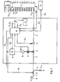
- 10 denotes a paint spray gun, which is fed by a paint supply line 11.
- the line 11 in turn is supplied with color by a color changing unit 12, which has a number of color connections 12 1 to 12 10 for different colors, an integrated flushing group 12 a with connections 12a 1 , 12a 2 and 12a 3 for purge air, solvent and sliding air and finally has an outlet valve 12b connected to line 11.
- a flow meter 13 In the line 11 there are a flow meter 13, a flow control valve 14 and a release valve 15 in the direction from the color changing unit 12 to the gun 10.
- the flow meter 13 transmits its measurement signals to a microcomputer 16 via a line 13a.
- the flow control valve 14 is actuated via a gear 17 by a stepping motor 18, which is connected via a control 19 to a voltage supply 20 which also serves to supply the microprocessor 16 with energy.
- the transmission 17 is connected to the microprocessor 16 via a signal line 17a and the control 19 via a control line 19a.
- the release valve 16, preferably a solenoid valve, can be actuated manually, for example via a reed contact of the gun trigger, via * via the connecting line 15a from the microcomputer 16. With 21 a usual return line with valve 21a is designated.
- the microcomputer 16 is also connected to an input display device 22, specifically via a setpoint line 22 1 , a color change line 22 2 and an enable line 22 3 . Finally, the microprocessor 16 is connected to the color changing unit 12 via a line 12c.
- 23 denotes a superordinate control, for example a mainframe to which the microcomputer. 16 is connected via line 23a.
- the operator inputs the desired color type and a target value for the flow into the microcomputer 16 via the input display device 22, with the result that the latter sets the color changing unit 12 accordingly and via the control unit 19 and / or the gear 17 controls the flow valve 14 to this target value.
- the operator now opens the release valve 15, for example by actuating the pistol trigger or by pressing a corresponding key on the input / display unit 22, then there is a color flow in line 11, the flow meter 13 giving the microcomputer 16 the actual values of Flow in line 11 transmitted. Based on these actual values, the microcomputer 16 regulates the flow valve 14 to the exact target value and ensures that this target value is maintained exactly.
- a flow rate table is created. This means that for each color for different flow values, the positions of the stepping motor 18 or the gear 17, which correspond to certain opening widths of the flow control valve 14, are determined. * If there is a linear dependency, then two data are sufficient for each color, if the dependency is not linear, then several table values must be created, the number of which depends on the required initial accuracy. In practice, the difference has been found that satisfactory results are achieved when the table error is less than ten percent of the table target value 'from the actual target value * Creating the table may also take place automatically by the microprocessor, however, for which a color flow (test spraying) is required. so does not exceed ten percent.
- the table values created are then stored in the microcomputer 16. If production is now started, the operator * - as mentioned - enters the desired flow rate target value g * into the microcomputer. The microcomputer then actuates the stepper motor 18 and / or the gear 17 on the basis of the stored table and thus sets the flow control valve 14 to an apriori value which corresponds to a flow rate close to the flow rate setpoint, for example with a deviation from maximum - 10%.
- the flow rate transmitter 13 continuously transmits the actual actual values of the flow rate to the microcomputer 16 and the microcomputer 16 regulates on the basis of a comparison between the actual value and the desired value the valve 14 until the actual value and the target value match, which can be considered in practice if the deviation is less than three percent.
- the microcomputer 16 calculates the new position of the stepper motor on the basis of the stored table and sets the valve 14 to the new apriori value, for which times up to a maximum of about 1 second are required. Then the above-mentioned control process takes place again until the target value and the actual value match.
- the apriori value can be set both in the idle state (no color flow) and in the operating state (color flow); the control process, on the other hand, understandably requires the presence of a color flow.
- the stored table it should be taken into account that, for a given opening width of the valve 14, the amount of passage depends on the viscosity of the paint flowing through, the viscosity in turn a function * or the higher-level control system ** and the desired color the temperature is. Temperature changes during the day therefore lead to the table, which is stored in the morning for example, becoming inaccurate. For this reason, it is expedient to provide the microcomputer with a table correction program which automatically corrects the table as a function of a temperature sensor or the deviations of the apriori values from the actual values measured by the flow sensor 13 during operation.
- the flow control valve 14 When changing the color, the flow control valve 14 is opened completely so as to keep the color change time as short as possible. During the color change, the line is flushed with solvent and purge air. It would not make sense to carry out flow measurements and / or controls because it is only important that the flushing process can be carried out quickly. After the rinse cycle, the valve 14 is set to the newly selected target value or returns to the target value before the color change.
- FIG. 2 shows a typical example of the control process according to the invention.
- the flow rate is given on the ordinate and the time course on the abscissa.
- the process therefore begins with a color change (full passage for the detergent) and ends with a color change, with three different target values 1, 2 and 3 being provided between these two color changes.
- the valve 14 With each change in the target value, the valve 14 is first set to the a priori value (table value), whereupon the control is carried out on the basis of the measured actual values.
- the apriori setting to the first target value is without color flow (release valve 15 closed), whereas the other two target values are with flowing paint (release valve 15 open).
- the process corresponds to the spraying of an automobile body, which is guided past the assembly line at the spraying station and has three zones of different paint application strength.
- a very inexpensive valve configuration with drive consists, for example, of a needle valve and a stepper motor.
- the needle valve has a spindle drive.
- This spindle can be connected directly to the drive shaft of the stepper motor via a coupling. This eliminates the gearbox and you also get a very high resolution of 1: 5000, for example.
- this valve arrangement consisting of a spindle-driven needle valve and stepper motor has good emergency running properties, because on the one hand the stepper motor and thus that The valve remains in its position and can also be mechanically adjusted by hand using a handwheel which is attached to the stepper motor axis.
- the possible modifications of the method relate in particular to the connection of the microcomputer to a higher-level system, such as a mainframe. This makes it possible, for example, to bring about an exchange of data between the workpiece conveyor and the spraying system in such a way that all the conditions of the workpiece supply are transferred to the spraying system and the latter thus operates fully automatically.
- the invention can be used with paint spraying devices of all kinds, that is to say both with rotary atomizers and with high-pressure atomizers as well as with compressed air atomizers, in which case a corresponding pressure flow control of the compressed air is also conceivable.
Landscapes
- Spray Control Apparatus (AREA)
- Application Of Or Painting With Fluid Materials (AREA)
Abstract
Description
- Die Erfindung betrifft ein Verfahren und eine Vorrichtung zum Einstellen der Farb-Durchflußmenge eines motorgetriebenen Durchfluß-Steuerventils einer Farbspritzpistole, insbesondere einer automatischen Farbspritzpistole mit häufigem Durchflußmengen- und Farbwechsel, vorzugsweise für das fließbandmäßige Spritzen von Automobilkarosserien.
- Bei den heutigen Farbspritzgeräten und -Anlagen werden zur Einstellung der Durchflußmenge mechanische oder elektrische Durchfluß-Stellglieder verwendet, die von Hand eingestellt werden müssen. Der jeweilige Ist-Wert des Durchflusses wird dabei von einer selbständigen Meßeinrichtung angezeigt und die Bedienungsperson nimmt dann auf der Grundlage des abgelesenen Wertes eine Korrektur vor. Bei komplizierteren Lackiervorgängen, etwa beim Lackieren von Automobilkarosserien, sind jedoch diese bekannten Verfahren bzw. Vorrichtungen zum Einstellen der Durchflußmenge unbefriedigend. So weist beispielsweise eine Automobilkarosserie mehrere Spritzzonen auf, also Zonen mit unterschiedlicher Stärke des Farbauftrags. Geht man nun beispielsweise davon aus, daß die Karosserie mit einer Bandgeschwindigkeit von fünf Meter pro Minute durch die Lackierstation hindurchgeführt wird, dann legt das Werkstück in einer Sekunde schon einen Wert von 8 cm zurück. Dabei liegen die Längen er erwähnten Spritzzonen zwischen etwa 30 cm und 100 cm. Damit nun eine Änderung der Durchflußmenge für die eingesetzte Farbspritzpistole für die einzelnen Spritzzonen voll wirksam wird, muß die Durchflußmengen-Einstellung sehr schnell erfolgen, d.h., der Übergang von der maximalen zur minimalen Durchflußmenge sollte innerhalb einer Sekunde möglich sein. Dies ist aber mit den erwähnten bekannten Einrichtungen nicht möglich, weil sowohl die eigentlichen Einstellzeiten als auch die Zeiten für das Messen und Ablesen der Ist-Werte in der Größenordnung von mehreren Sekunden liegen. Soll zwischen zwei Werkstücken ein Farbwechsel erfolgen, dann muß ein Spülvorgang durchgeführt werden, der ein voll geöffnetes Durchlaßventil erfordert. Anschließend ist das Ventil dann auf die Durchflußmenge der ersten Spritzzone des nächsten Werkstücks einzustellen. Hierdurch ergeben sich gerade beim Farbwechsel beträchtliche Zeitverzögerungen. Zu Berücksichtigen ist ferner, daß die Durchlußmenge von der Viskosität der jeweiligen Farbe und damit auch von der Umgebungstemperatur abhängt, mit der Folge, daß sich die Einstellwerte während eines Produktionstages ändern. Die erwähnten Probleme führen jedenfalls dazu, daß das Einstellen der erforderlichen Durchflußmengen nicht nur mühsam und zeitraubend ist, sondern zwangsläufig Abweichungen von 20 Prozent und weit darüber in Kauf genommen werden müssen.
- Aufgabe der vorliegenden Erfindung ist es deshalb, ein Verfahren und eine Vorrichtung zu schaffen, mit deren Hilfe es gelingt, eine selbsttätige Einstellung der Durchflußmenge in kürzester Zeit und mit hoher Genauigkeit vorzunehmen. Die verfahrensmäßige Lösung dieser Aufgabe ist im Patentanspruch 1, die vorrichtungsmäßige Lösung im Patentanspruch 3 gekennzeichnet.
- Erfindungsgemäß wird also zunächst eine Steuerung und dann eine Regelung vorgenommen. Die Steuerung dient dazu, das Durchflußventil möglichst schnell auf den ungefähren Soll- Wert einzustellen, und zwar unabhängig davon, ob ein Farbfluß vorhanden ist oder nicht. Diese ungefähre Einstellung des Soll-Werts kann also bereits vor Freigabe des Farbflusses durchgeführt werden. Anschließend an dieses ungefähre Ansteuern des Soll-Werts erfolgt dann - bei Farbfluß - eine Einregelung auf den exakten Soll-Wert im geschlossenen Regelkreis. Damit wird es möglich, selbst dann, wenn die einzelnen Spritzvorgänge sehr kurz sind, beispielsweise zwischen 0,5 und 1 Sekunde liegen, exakte Durchflußmengen zu erhalten. Darüberhinaus wird die Erfindung auch besonderen Fällen, wie etwa Farbwechsel, Farbunterbrechung u.dgl., in besonderem Maße gerecht, wie sich aus der nachfolgenden Beschreibung noch im einzelnen ergeben wird.
- Auf der Zeichnung ist eine Ausführungsform der erfindungsgemäßen Vorrichtung beispielsweise dargestellt. Es zeigen:
- Fig. 1 eine Blockschaltskizze der Gesamtvorrichtung, und
- Fig.2 ein Diagramm zur Erläuterung des Steuer-und Regelvorgangs.
- In Figur 1 ist mit 10 eine Farbspritzpistole bezeichnet, die von einer Farbzuführleitung 11 gespeist wird. Die Leitung 11 ihrerseits wird von einer Farbwechseleinheit 12 mit Farbe versorgt, die eine Reihe von Farbanschlüssen 121 bis 1210 für verschiedene Farben, eine in ihr integrierte Spülgruppe 12 a mit Anschlüssen 12a1, 12a2 und 12a3 für Spülluft, Lösemittel und Schiebeluft und schließlich ein mit der Leitung 11 verbundenes Auslaßventil 12b aufweist. In der Leitung 11 befinden sich - in Richtung von der Farbwechseleinheit 12 zur Pistole 10 - ein Durchflußmeßgeber 13, ein Durchfluß-Steuerventil 14 und ein Freigabeventil 15. Der Durchflußmeßgeber 13 gibt seine Meßsignale über eine Leitung 13a an einen Mikrocomputer 16 weiter. Das Durchfluß-Steuerventil 14 wird über ein Getriebe 17 von einem Schrittschaltmotor 18 betätigt, der über eine Ansteuerung 19 an einer Spannungsversorgung 20 liegt, die auch zur Energieversorgung des Mikroprozessors 16 dient. Das Getriebe 17 ist über eine Meldeleitung 17a und die Ansteuerung 19 über eine Steuerleitung 19a mit dem Mikroprozessor 16 verbunden. Das Freigabeventil 16, vorzugsweise ein Magnetventil, kann manuell, etwa über einen Reed-Kontakt des Pistolenabzugs, über * über die Verbindungsleitung 15a vom Mikrocomputer 16 aus betätigt werden. Mit 21 ist eine übliche Rückführleitung mit Ventil 21a bezeichnet.
- Der Mikrocomputer 16 ist ferner mit einer Eingabe-Anzeige-Einrichtung 22 verbunden, und zwar über eine Sollwertleitung 221, eine Farbwechselleitung 222 und eine Freigabeleitung 223. Schließlich ist der Mikroprozessor 16 über eine Leitung 12c mit der Farbwechseleinheit 12 verbunden.
- Mit 23 ist eine übergeordnete Steuerung bezeichnet, beispielsweise ein Großrechner, an welche der Mikrocomputer . 16 über die Leitung 23a angeschlossen ist.
- * ein übergeordnetes Steuersystem, oder
- Für den Betrieb der Anlage gibt die Bedienungsperson über die Eingabe-Anzeige-Einrichtung 22 die gewünschte Farbart und einen Soll-Wert für den Durchfluß in den Mikrocomputer 16 ein, mit der Folge, daß dieser die Farbwechseleinheit 12 entsprechend einstellt und über die Ansteuereinheit 19 und/ oder das Getriebe 17 das Durchflußventil 14 auf diesen Soll- Wert einsteuert. öffnet nun die Bedienungsperson das Freigabeventil 15, etwa durch Betätigen des Pistolenabzugs oder durch Druck auf eine entsprechende Taste der Eingabe-Anzeige-Einheit 22, dann ergibt sich in der Leitung 11 eine Farbströmung, wobei der Durchflußmeßgeber 13 dem Mikrocomputer 16 die Ist-Werte des Durchflusses in der Leitung 11 übermittelt. Aufgrund dieser Ist-Werte regelt der Mikrocomputer 16 das Durchflußventil 14 auf den exakten Soll-Wert ein und sorgt dafür, daß dieser Soll-Wert exakt beibehalten wird. Wesentlich dabei ist, daß zunächst eine schnelle Steuerung des Durchlaßventils 14 auf den - ungefähren - Soll-Wert erfolgt, wobei dies sowohl bei offenem als auch bei geschlossenem Freigabeventil 15 erfolgen kann, und daß dann auf der Grundlage der Messung der tatsächlichen Durchflußwerte, also der Ist-Werte, ein Regelvorgang zur Erzielung und Erhaltung des exakten Soll-Werts durchgeführt wird.
- Vor der ersten Inbetriebnahme, beispielsweise am Morgen vor Produktionsbeginn, wird eine Durchflußmengen-Tabelle erstellt. Das bedeutet, daß man für jede Farbe für verschiedene Durchflußwerte die Positionen des Schrittmotors 18 bzw. des Getriebes 17, welche bestimmten öffnungsweiten des Durchfluß-Steuerventils 14 entsprechen, festlegt.*Liegt eine lineare Abhängigkeit vor, dann genügen für jede Farbe zwei Daten, ist die Abhängigkeit nicht linear, dann sind mehrere Tabellenwerte zu erstellen, wobei deren Anzahl von der geforderten Anfangsgenauigkeit abhängt. In der Praxis hat sich gezeigt, daß zufriedenstellende Ergebnisse dann erreicht werden, wenn der Tabellenfehler unter zehn Prozent liegt, die Abweichung des Tabellen-Soll-Wertes' vom tatsächlichen Soll-Wert * Das Erstellen der Tabelle kann aber auch selbsttätig durch den Mikroprozessor erfolgen, wozu jedoch ein Farbfluß (Test-Sprühen) erforderlich ist. also zehn Prozent nicht überschreitet. Die erstellten Tabellenwerte werden dann im Mikrocomputer 16 abgespeichert. Wird nun die Produktion begonnen, dann gibt die Bedienungsperson * - wie erwähnt - in den Mikrocomputer den gewünschten.Durchflußmengen-Soll-Wertg*ein. Der Mikrocomputer betätigt dann auf der Grundlage der abgespeicherten Tabelle den Schrittmotor 18 und/oder das Getriebe 17 und stellt damit das Durchfluß-Steuerventil 14 auf einen Apriori-Wert ein, der einer Durchflußmenge nahe dem Durchflußmengen-Soll-Wert, beispielsweise mit einer Abweichung von maximal - 10 %, entspricht. Wird durch öffnen des Freigabeventils 15 die Strömung in der Leitung 11 in Gang gesetzt, dann übermittelt der Durchflußmengengeber 13 dem Mikrocomputer 16 fortlaufend die tatsächlichen Ist-Werte der Durchflußmenge und der Mikrocomputer 16 regelt auf der Grundlage eines Vergleichs zwischen Ist-Wert und Soll-Wert das Ventil 14 nach, bis Ist-Wert und Soll-Wert übereinstimmen, was in der Praxis als gegeben angesehen werden kann, wenn die Abweichung unter drei Prozent liegt. Wird ein neuer Soll-Wert eingegeben, dann errechnet der Mikrocomputer 16 auf der Grundlage der abgespeicherten Tabelle die neue Position des Schrittmotors und stellt das Ventil 14 auf den neuen Apriori-Wert ein, wozu Zeiten bis maximal etwa 1 Sekunde erforderlich sind. Anschließend erfolgt dann wiederum der erwähnte Regelvorgang bis zur Erreichung der Übereinstimmung zwischen Soll-Wert und Ist-Wert. Wie erwähnt kann dabei die Einstellung des Apriori-Wertes sowohl im Ruhezustand (keine Farbströmung) als auch im Betriebszustand (Farbströmung) erfolgen; der Regelvorgang dagegen erfordert verständlicherweise das Vorliegen einer Farbströmung.
- Bezüglich der abgespeicherten Tabelle ist zu berücksichtigen, daß bei gegebener öffnungsweite des Ventils 14 die Durchlaßmenge von der Viskosität der hindurchströmenden Farbe abhängig ist, wobei die Viskosität ihrerseits eine Funktion
* oder das übergeordnete Steuerungssystem
** und die gewünschte Farbe der Temperatur ist. Temperaturänderungen während des Tages führen also dazu, daß die beispielsweise am Morgen abgespeicherte Tabelle ungenauer wird. Aus diesem Grund ist es zweckmäßig, den Mikrocomputer mit einem Tabellen-Korrekturprogramm zu versehen, das in Abhängigkeit von einem Temperaturgeber oder von den während des Betriebs vom Durchflußgeber 13 gemessenen Abweichungen der Apriori-Werte von den Ist-Werten selbsttätig eine Korrektur der Tabelle vornimmt. - Beim Farbwechsel wird das Durchfluß-Steuerventil 14 ganz geöffnet, um so die Farbwechselzeit möglichst kurz zu halten. Während des Farbwechsels erfolgt nämlich eine Spülung der Leitung mit Lösungsmittel und Spülluft. Dabei wäre es nicht sinnvoll, Durchflußmessungen und/oder Regelungen vorzunehmen, weil lediglich von Bedeutung ist, daß der Spülvorgang schnell durchgeführt werden kann. Nach dem Spülgang wird das Ventil 14 auf den neu angewählten Soll-Wert eingestellt bzw. kehrt zu dem Soll-Wert vor Farbwechsel zurück.
- Figur 2 zeigt ein typisches Beispiel für den Steuerungs- und Regelvorgang nach der Erfindung. Dabei ist auf der Ordinate die Durchflußmenge, auf der Abszisse der Zeitablauf angegeben. Der Vorgang beginnt also mit einem Farbwechsel (voller Durchlaß für das Spülmittel) und endet mit einem Farbwechsel, wobei zwischen diesen beiden Farbwechseln drei verschiedene Soll-Werte 1, 2 und 3 vorgesehen sind. Bei jeder Soll-Wert- Änderung wird zunächst das Ventil 14 auf den Apriori-Wert (Tabellenwert) eingestellt, worauf dann die Regelung auf der Grundlage der gemessenen Ist-Werte erfolgt. Im gezeichneten Beispiel ist dabei angenommen worden, daß die Apriori-Einstellung auf den ersten Soll-Wert ohne Farbfluß (Freigabeventil 15 geschlossen), bei den beiden anderen Soll-Werten dagegen bei strömender Farbe (Freigabeventil 15 geöffnet) erfolgt. Der Vorgang entspricht in der Praxis dem Spritzen einer Automobilkarosserie, die am Fließband an der Spritzstation vorbeigeführt wird und drei Zonen unterschiedlicher Farbauftragsstärke aufweist.
- Sowohl die Vorrichtung als auch das Verfahren können Abwandlungen erfahren, ohne den Bereich der Erfindung zu verlassen. Eine sehr kostengünstige Ventilkonfiguration mit Antrieb besteht beispielsweise aus einem Nadelventil und einem Schrittmotor. Das Nadelventil besitzt einen Spindelantrieb. Diese Spindel ist direkt über eine' Kupplung mit der Antriebswelle des Schrittmotors verbindbar. Es entfällt damit das Getriebe und man erhält außerdem eine sehr hohe Auflösung von beispielsweise 1 : 5000. Im Falle einer Störung im Steuerungssystem oder in der elektrischen Versorgung besitzt dann diese Ventilanordnung aus spindelgetriebenem Nadelventil und Schrittmotor gute Notlaufeigenschaften, da zum einen der Schrittmotor und damit das Ventil in seiner Position verharren und zum anderen mit der Hand über ein Handrad, welches auf der Schrittmotorachse befestigt ist, mechanisch eingestellt werden kann. Die möglichen Modifikationen des Verfahrens betreffen insbesondere den Anschluß des Mikrocomputers an eine übergeordnete Anlage, etwa einen Großrechner. Damit wird es beispielsweise möglich, einen Datenaustausch zwischen der Werkstück-Fördereinrichtung und der Spritzanlage herbeizuführen, derart, daß alle Gegebenheiten der Werstückszuführung auf die Spritzanlage übertragen werden und diese damit vollautomatisch arbeitet.
- Die Erfindung ist bei Farbspritzgeräten aller Art anwendbar, also sowohl bei Rotationszerstäubern als auch bei Hochdruckzerstäubern als auch bei Druckluftzerstäubern, wobei im letzteren Fall auch eine entsprechende Druckströmungssteuerung der Druckluft denkbar ist.
Claims (7)
Applications Claiming Priority (2)
| Application Number | Priority Date | Filing Date | Title |
|---|---|---|---|
| DE3423094 | 1984-06-22 | ||
| DE19843423094 DE3423094A1 (de) | 1984-06-22 | 1984-06-22 | Verfahren und vorrichtung zum einstellen eines durchflussmengen-steuerventils einer farbspritzpistole |
Publications (2)
| Publication Number | Publication Date |
|---|---|
| EP0166092A1 true EP0166092A1 (de) | 1986-01-02 |
| EP0166092B1 EP0166092B1 (de) | 1988-12-21 |
Family
ID=6238920
Family Applications (1)
| Application Number | Title | Priority Date | Filing Date |
|---|---|---|---|
| EP85104010A Expired EP0166092B1 (de) | 1984-06-22 | 1985-04-02 | Verfahren und Vorrichtung zum Einstellen eines Durchflussmengen Steuerventils einer Farbspritzpistole |
Country Status (4)
| Country | Link |
|---|---|
| US (1) | US4720801A (de) |
| EP (1) | EP0166092B1 (de) |
| JP (1) | JPS6111169A (de) |
| DE (1) | DE3423094A1 (de) |
Cited By (10)
| Publication number | Priority date | Publication date | Assignee | Title |
|---|---|---|---|---|
| DE3721875A1 (de) * | 1987-07-02 | 1989-01-12 | Gema Ransburg Ag | Verfahren und einrichtung fuer eine pulverspruehbeschichtungsanlage |
| FR2618087A1 (fr) * | 1987-07-15 | 1989-01-20 | Graco France Sa | Procede de selection d'un fluide avec commande et regulation de son debit et dispositif mettant en oeuvre le procede et installation d'application de peinture avec selection de couleur mettant en oeuvre le procede |
| EP0310272A1 (de) * | 1987-09-28 | 1989-04-05 | Illinois Tool Works Inc. | Regeleinrichtung für eine Spritzpistole |
| EP0288877A3 (en) * | 1987-04-27 | 1989-10-11 | Behr Industrieanlagen Gmbh & Co. | Control system for a programmed spraying device |
| EP0288878A3 (en) * | 1987-04-27 | 1989-10-18 | Behr Industrieanlagen Gmbh & Co. | Method for automatically coating work pieces in series |
| WO1989011340A1 (en) * | 1988-05-18 | 1989-11-30 | Advanced Flow Control Afc Aktiebolag | Method and device for regulating the spraying of coating materials |
| DE3822835A1 (de) * | 1988-07-06 | 1990-03-08 | Josef Schucker | Verfahren und anordnung zum lackieren von werkstueckoberflaechen |
| EP0403280A3 (de) * | 1989-06-16 | 1991-10-23 | Nordson Corporation | Vorrichtung zur Regelung des Materialflusses bei einem Prozess mit Abgabe eines fliessfähigen Mediums |
| DE102006002389A1 (de) * | 2006-01-17 | 2007-07-19 | SCHÜTZE, Thomas | System zur Zuführung mehrere Farbkomponenten für mindestens eine Lackierstation, insbesondere für Kraftfahrzeugkarosserien |
| DE102007062132A1 (de) * | 2007-12-21 | 2009-07-02 | Dürr Systems GmbH | Testverfahren und Testgerät zur Funktionsprüfung einer Lackiereinrichtung |
Families Citing this family (25)
| Publication number | Priority date | Publication date | Assignee | Title |
|---|---|---|---|---|
| JPS6274110A (ja) * | 1985-09-27 | 1987-04-04 | Toyota Motor Corp | 粘性流体の流量制御方法及び装置 |
| US4992952A (en) * | 1987-09-21 | 1991-02-12 | Mazda Motor Corporation | Paint discharge rate control system |
| US4858172A (en) * | 1987-10-05 | 1989-08-15 | Robotic Vision Systems | Sealant flow control for robotic applications |
| US4879662A (en) * | 1988-03-11 | 1989-11-07 | Sundstrand Corporation | Fluid flow self calibration scheme |
| FI882260L (fi) * | 1988-05-13 | 1989-11-14 | Saab Valmet Ab Oy | Faergbytes- och tvaettfoerfarande foer att anvaendas i en anordning foer utbredning av belaeggningsaemne, foerdelaktigt maolfaerg och anlaeggning foer anvaendning vid foerfarandet. |
| US5289388A (en) * | 1989-04-21 | 1994-02-22 | Vickers, Incorporated | Electrohydraulic control of a die casting machine |
| DE8915968U1 (de) * | 1989-08-11 | 1992-12-17 | Gema Volstatic Ag, St. Gallen | Elektrostatische Pulverbeschichtungseinrichtung |
| DE3927880C2 (de) * | 1989-08-23 | 1998-07-30 | Behr Industrieanlagen | Verfahren und Anlage zum Beschichten von Gegenständen mit häufig wechselndem Farbmaterial |
| JPH05231546A (ja) * | 1991-03-07 | 1993-09-07 | Fanuc Ltd | 産業用ロボットによるシーリングにおけるシール材流量制御方法 |
| ES2075689T5 (es) * | 1991-03-27 | 2000-10-16 | Sca Schucker Gmbh | Procedimiento y dispositivo para aplicar una masa pastosa. |
| DE4325044C2 (de) † | 1993-07-26 | 2002-07-18 | Itw Gema Ag | Pulverfördervorrichtung, insbesondere für Beschichtungspulver |
| US5389149A (en) * | 1993-12-08 | 1995-02-14 | Monarch Design Company, Inc. | Paint system |
| WO1996014162A1 (en) * | 1994-11-02 | 1996-05-17 | Becton, Dickinson And Company | Micrometer adjusted airbrush |
| US5687092A (en) * | 1995-05-05 | 1997-11-11 | Nordson Corporation | Method of compensating for changes in flow characteristics of a dispensed fluid |
| US6190454B1 (en) | 1997-06-19 | 2001-02-20 | Dean Robert Gary Anderson | Printer cartridge |
| US5944893A (en) * | 1997-06-19 | 1999-08-31 | Anderson; Dean Robert Gary | Metering device for paint for digital printing |
| US5972111A (en) | 1997-06-19 | 1999-10-26 | Anderson; Dean Robert Gary | Metering device for paint for digital printing |
| US6786971B2 (en) | 1997-06-19 | 2004-09-07 | Dean Robert Gary Anderson | Method and apparatus for digital printing |
| DE10139633C1 (de) * | 2001-08-11 | 2003-04-24 | Amtec Kistler Gmbh | Vorrichtung zum Auftragen eines Beschichtungsmittels |
| DE10142355A1 (de) * | 2001-08-30 | 2003-03-20 | Duerr Systems Gmbh | Beschichtungsanlage mit einem Regelkreis |
| JP4618132B2 (ja) | 2004-01-28 | 2011-01-26 | 東レ株式会社 | 糸道ガイド、繊維束パッケージの製造方法および製造装置 |
| JP5231891B2 (ja) * | 2008-07-31 | 2013-07-10 | アネスト岩田株式会社 | 空圧制御弁を用いた塗料供給制御方法 |
| KR102379338B1 (ko) | 2014-05-01 | 2022-03-29 | 그라코 미네소타 인크. | 고-과도 시스템의 유동 제어 교정 방법 |
| KR102379148B1 (ko) | 2014-05-01 | 2022-03-25 | 그라코 미네소타 인크. | 폐쇄 시스템 내의 유체 압력 제어 방법 |
| US11950677B2 (en) | 2019-02-28 | 2024-04-09 | L'oreal | Devices and methods for electrostatic application of cosmetics |
Citations (2)
| Publication number | Priority date | Publication date | Assignee | Title |
|---|---|---|---|---|
| US3674205A (en) * | 1971-05-14 | 1972-07-04 | Champion Spark Plug Co | Multiple color paint spray system |
| DE2819302B2 (de) * | 1978-05-02 | 1980-12-18 | Ransburg Gmbh, 6056 Heusenstamm | Lackmengensteuersystem |
Family Cites Families (16)
| Publication number | Priority date | Publication date | Assignee | Title |
|---|---|---|---|---|
| US3674207A (en) * | 1970-11-06 | 1972-07-04 | Emidio J Carbonetti Jr | Automated paint spray system |
| US3981320A (en) * | 1974-05-10 | 1976-09-21 | The Gyromat Corporation | Recovery system for spray painting installation with automatic color change |
| US4019653A (en) * | 1975-08-22 | 1977-04-26 | Graco Inc. | Automatic proportioning paint spray system |
| SE398984B (sv) * | 1976-05-25 | 1978-01-30 | Asea Ab | Ugn for behandling av material vid hog temperatur i en gasatmosfer under hogt tryck |
| GB1556013A (en) * | 1978-04-19 | 1979-11-14 | Carrier Drysys Ltd | Paint spraying apparatus |
| US4362124A (en) * | 1978-05-02 | 1982-12-07 | Ransburg Corporation | Analog paint output control |
| FR2466944A1 (fr) * | 1979-10-15 | 1981-04-17 | Lestradet M C J | Vehicule equipe d'un dispositif d'epandage d'un liquide |
| GB2064826A (en) * | 1979-11-28 | 1981-06-17 | Agmet Instr | Apparatus for controlling application of spraying fluid by spraying equipment |
| US4328549A (en) * | 1980-01-11 | 1982-05-04 | Olin Corporation | Process flow computer control system |
| US4360877A (en) * | 1980-04-08 | 1982-11-23 | Tokheim Corporation | Distributed data processing system and method for a fluid dispenser |
| JPS57201560A (en) * | 1981-03-27 | 1982-12-10 | Biieru Tekunorojii Ltd | Method and device for spraying medium |
| US4392611A (en) * | 1981-05-15 | 1983-07-12 | Dickey-John Corporation | Sprayer control system |
| JPS5870857A (ja) * | 1981-10-21 | 1983-04-27 | Furointo Sangyo Kk | 自動コ−チング装置 |
| EP0086031A1 (de) * | 1982-02-05 | 1983-08-17 | Imperial Chemical Industries Plc | Sprühvorrichtung |
| WO1984001312A1 (en) * | 1982-09-30 | 1984-04-12 | Ford Werke Ag | Color change apparatus |
| US4593360A (en) * | 1983-12-16 | 1986-06-03 | Cocks Eric H | Fluid spray control system |
-
1984
- 1984-06-22 DE DE19843423094 patent/DE3423094A1/de active Granted
-
1985
- 1985-04-02 EP EP85104010A patent/EP0166092B1/de not_active Expired
- 1985-06-11 US US06/743,639 patent/US4720801A/en not_active Expired - Fee Related
- 1985-06-21 JP JP60134455A patent/JPS6111169A/ja active Pending
Patent Citations (2)
| Publication number | Priority date | Publication date | Assignee | Title |
|---|---|---|---|---|
| US3674205A (en) * | 1971-05-14 | 1972-07-04 | Champion Spark Plug Co | Multiple color paint spray system |
| DE2819302B2 (de) * | 1978-05-02 | 1980-12-18 | Ransburg Gmbh, 6056 Heusenstamm | Lackmengensteuersystem |
Cited By (14)
| Publication number | Priority date | Publication date | Assignee | Title |
|---|---|---|---|---|
| EP0288877A3 (en) * | 1987-04-27 | 1989-10-11 | Behr Industrieanlagen Gmbh & Co. | Control system for a programmed spraying device |
| EP0288878A3 (en) * | 1987-04-27 | 1989-10-18 | Behr Industrieanlagen Gmbh & Co. | Method for automatically coating work pieces in series |
| US4941778A (en) * | 1987-07-02 | 1990-07-17 | Ransburg-Gema Ag | Method and apparatus for measuring and regulating the flow rate of powder in a powder spraying device |
| EP0297309A3 (en) * | 1987-07-02 | 1989-10-18 | Ransburg-Gema Ag | Process and device for metering and regulating the powder flow in a powder spray coating installation |
| DE3721875A1 (de) * | 1987-07-02 | 1989-01-12 | Gema Ransburg Ag | Verfahren und einrichtung fuer eine pulverspruehbeschichtungsanlage |
| FR2618087A1 (fr) * | 1987-07-15 | 1989-01-20 | Graco France Sa | Procede de selection d'un fluide avec commande et regulation de son debit et dispositif mettant en oeuvre le procede et installation d'application de peinture avec selection de couleur mettant en oeuvre le procede |
| EP0310272A1 (de) * | 1987-09-28 | 1989-04-05 | Illinois Tool Works Inc. | Regeleinrichtung für eine Spritzpistole |
| WO1989011340A1 (en) * | 1988-05-18 | 1989-11-30 | Advanced Flow Control Afc Aktiebolag | Method and device for regulating the spraying of coating materials |
| DE3822835A1 (de) * | 1988-07-06 | 1990-03-08 | Josef Schucker | Verfahren und anordnung zum lackieren von werkstueckoberflaechen |
| EP0403280A3 (de) * | 1989-06-16 | 1991-10-23 | Nordson Corporation | Vorrichtung zur Regelung des Materialflusses bei einem Prozess mit Abgabe eines fliessfähigen Mediums |
| US6139903A (en) * | 1989-06-16 | 2000-10-31 | Nordson Corporation | Method of compensating for non-linear characteristics in dispensing a coating material |
| DE102006002389A1 (de) * | 2006-01-17 | 2007-07-19 | SCHÜTZE, Thomas | System zur Zuführung mehrere Farbkomponenten für mindestens eine Lackierstation, insbesondere für Kraftfahrzeugkarosserien |
| DE102007062132A1 (de) * | 2007-12-21 | 2009-07-02 | Dürr Systems GmbH | Testverfahren und Testgerät zur Funktionsprüfung einer Lackiereinrichtung |
| US8567694B2 (en) | 2007-12-21 | 2013-10-29 | Durr Sysems GmbH | Test method and test apparatus for checking the function of a painting device |
Also Published As
| Publication number | Publication date |
|---|---|
| EP0166092B1 (de) | 1988-12-21 |
| DE3423094A1 (de) | 1986-01-02 |
| US4720801A (en) | 1988-01-19 |
| JPS6111169A (ja) | 1986-01-18 |
| DE3423094C2 (de) | 1990-10-04 |
Similar Documents
| Publication | Publication Date | Title |
|---|---|---|
| EP0166092B1 (de) | Verfahren und Vorrichtung zum Einstellen eines Durchflussmengen Steuerventils einer Farbspritzpistole | |
| CH620600A5 (de) | ||
| DE68909943T2 (de) | Verfahren und vorrichtung zur regelung des spritzens von beschichtungsmaterialien. | |
| DE3713999A1 (de) | Verfahren zum selbsttaetigen serienweisen beschichten von werkstuecken | |
| DE2819302C3 (de) | Lackmengen-Steuersystem | |
| DE3220360A1 (de) | Einrichtung zur beeinflussung der farbgebung an druckmaschinen | |
| DE3305725C2 (de) | ||
| DE3009405A1 (de) | Verfahren und anordnung zur steuerung elektrisch gesteuerter fuellelemente in fuellmaschinen | |
| DE69327315T2 (de) | Verfahren und vorrichtung zum auftragen von fluid, insbesondere von hot melt, auf ein substrat durch ein sequentielles auftragegerät | |
| DE10239351A1 (de) | Vorrichtung zum Auftragen eines Beschichtungsmittels | |
| DE2063574B2 (de) | ||
| DE2044020B2 (de) | Kalander zum Herstellen einer zweischichtigen Verbundbahn | |
| EP0222379A2 (de) | Vorrichtung zum Versprühen von Auftragmassen | |
| EP0288877B1 (de) | Steuersystem für eine programmgesteuerte Sprühvorrichtung | |
| DE1474263B2 (de) | Vorrichtung zum mittelliniengleichen Ausrichten zweier zu verbindender Bahnenden | |
| DE1910787C3 (de) | Anordnung zur Regelung der Luftzufuhr an wenigstens einer Luftbürste | |
| DE10130499A1 (de) | Beschichtungsanlage und Verfahren zum Steuern einer Beschichtungsvorrichtung mit unterschiedlichen Düsen | |
| DE4436582C2 (de) | Verfahren zur Regelung einer Feuchtmittelmenge für eine Druckform einer laufenden Offsetrotationsdruckmaschine | |
| DE8133609U1 (de) | "vorrichtung zum regeln eines zentrifugalzerstaeubers" | |
| EP0735443A2 (de) | Neuronales Netz zur Positionsabweichungskompensation bei Werkstückbearbeitungseinrichtungen | |
| DE3800788C2 (de) | ||
| DE4332069A1 (de) | Anordnung zum Auftragen von Leim auf Buchblockrücken | |
| EP0565853B1 (de) | Verfahren zur Regelung der Vorlauftemperatur einer Heizungsanlage und Regelgerät zur Durchführung des Verfahrens | |
| DE1958325C3 (de) | Anordnung zweier in Kaskade schaltbarer Druckluftregler | |
| DE3313287A1 (de) | Misch- und spueleinrichtung |
Legal Events
| Date | Code | Title | Description |
|---|---|---|---|
| PUAI | Public reference made under article 153(3) epc to a published international application that has entered the european phase |
Free format text: ORIGINAL CODE: 0009012 |
|
| AK | Designated contracting states |
Designated state(s): BE FR GB IT SE |
|
| RAP1 | Party data changed (applicant data changed or rights of an application transferred) |
Owner name: J. WAGNER GMBH |
|
| 17P | Request for examination filed |
Effective date: 19860131 |
|
| 17Q | First examination report despatched |
Effective date: 19860924 |
|
| R17C | First examination report despatched (corrected) |
Effective date: 19861117 |
|
| D17Q | First examination report despatched (deleted) | ||
| GRAA | (expected) grant |
Free format text: ORIGINAL CODE: 0009210 |
|
| AK | Designated contracting states |
Kind code of ref document: B1 Designated state(s): BE FR GB IT SE |
|
| ITF | It: translation for a ep patent filed | ||
| ET | Fr: translation filed | ||
| GBT | Gb: translation of ep patent filed (gb section 77(6)(a)/1977) | ||
| PLBE | No opposition filed within time limit |
Free format text: ORIGINAL CODE: 0009261 |
|
| STAA | Information on the status of an ep patent application or granted ep patent |
Free format text: STATUS: NO OPPOSITION FILED WITHIN TIME LIMIT |
|
| 26N | No opposition filed | ||
| ITTA | It: last paid annual fee | ||
| PGFP | Annual fee paid to national office [announced via postgrant information from national office to epo] |
Ref country code: GB Payment date: 19920313 Year of fee payment: 8 |
|
| PGFP | Annual fee paid to national office [announced via postgrant information from national office to epo] |
Ref country code: SE Payment date: 19920316 Year of fee payment: 8 |
|
| PGFP | Annual fee paid to national office [announced via postgrant information from national office to epo] |
Ref country code: FR Payment date: 19920330 Year of fee payment: 8 |
|
| PGFP | Annual fee paid to national office [announced via postgrant information from national office to epo] |
Ref country code: BE Payment date: 19920410 Year of fee payment: 8 |
|
| PG25 | Lapsed in a contracting state [announced via postgrant information from national office to epo] |
Ref country code: GB Effective date: 19930402 |
|
| PG25 | Lapsed in a contracting state [announced via postgrant information from national office to epo] |
Ref country code: SE Effective date: 19930403 |
|
| PG25 | Lapsed in a contracting state [announced via postgrant information from national office to epo] |
Ref country code: BE Effective date: 19930430 |
|
| BERE | Be: lapsed |
Owner name: J. WAGNER G.M.B.H. Effective date: 19930430 |
|
| GBPC | Gb: european patent ceased through non-payment of renewal fee |
Effective date: 19930402 |
|
| PG25 | Lapsed in a contracting state [announced via postgrant information from national office to epo] |
Ref country code: FR Effective date: 19931229 |
|
| REG | Reference to a national code |
Ref country code: FR Ref legal event code: ST |
|
| EUG | Se: european patent has lapsed |
Ref document number: 85104010.5 Effective date: 19931110 |