EP0166111A1 - Appareil de commande électronique - Google Patents
Appareil de commande électronique Download PDFInfo
- Publication number
- EP0166111A1 EP0166111A1 EP85105126A EP85105126A EP0166111A1 EP 0166111 A1 EP0166111 A1 EP 0166111A1 EP 85105126 A EP85105126 A EP 85105126A EP 85105126 A EP85105126 A EP 85105126A EP 0166111 A1 EP0166111 A1 EP 0166111A1
- Authority
- EP
- European Patent Office
- Prior art keywords
- molded part
- housing
- potentiometer
- control device
- section
- Prior art date
- Legal status (The legal status is an assumption and is not a legal conclusion. Google has not performed a legal analysis and makes no representation as to the accuracy of the status listed.)
- Granted
Links
- 238000003780 insertion Methods 0.000 claims abstract description 5
- 230000037431 insertion Effects 0.000 claims abstract description 5
- 239000004020 conductor Substances 0.000 claims description 3
- 239000004033 plastic Substances 0.000 claims description 2
- 238000007789 sealing Methods 0.000 description 3
- 238000004519 manufacturing process Methods 0.000 description 2
- 239000004952 Polyamide Substances 0.000 description 1
- 238000011161 development Methods 0.000 description 1
- 230000018109 developmental process Effects 0.000 description 1
- 239000000463 material Substances 0.000 description 1
- 229920002647 polyamide Polymers 0.000 description 1
Images

Classifications
-
- H—ELECTRICITY
- H05—ELECTRIC TECHNIQUES NOT OTHERWISE PROVIDED FOR
- H05K—PRINTED CIRCUITS; CASINGS OR CONSTRUCTIONAL DETAILS OF ELECTRIC APPARATUS; MANUFACTURE OF ASSEMBLAGES OF ELECTRICAL COMPONENTS
- H05K5/00—Casings, cabinets or drawers for electric apparatus
- H05K5/06—Hermetically-sealed casings
- H05K5/069—Other details of the casing, e.g. wall structure, passage for a connector, a cable, a shaft
-
- H—ELECTRICITY
- H01—ELECTRIC ELEMENTS
- H01C—RESISTORS
- H01C10/00—Adjustable resistors
- H01C10/14—Adjustable resistors adjustable by auxiliary driving means
Definitions
- the invention is based on an electronic control device according to the preamble of the main claim.
- the control device for the potentiometer used in such a control device consists of a molded part.
- the molded part is inserted into a bore in the housing from the inside of the housing.
- the known molded part can only be deflected to compensate for tolerances perpendicular to its longitudinal axis.
- the disadvantage here is that the mounting of the circuit board carrying the potentiometer in the housing and the molded part arranged in the housing cover, and here in particular the insertion of the adjusting section into the slot of a central potentiometer, is difficult and can easily lead to damage to the potentiometer.
- an adjusting device for a spiral potentiometer is known. It consists of one held on the inside of the housing by means of an additional part and from the outside of the housing-operated adjusting bolt, on which one end of a wave-shaped leaf spring accommodated in the housing is detachably fastened, the other end of which is also releasably fastened to the adjusting screw of the potentiometer.
- the cumbersome assembly of the multi-part adjusting device is also disadvantageous here.
- the distance between the adjusting pin and the potentiometer must be observed very precisely in order not to overload the spring or to undesirably influence the potentiometer due to mechanical loads.
- the electronic control device with the characterizing features of the main claim has the advantage that the one-piece adjusting device for the potentiometer arranged on the printed circuit board can be inserted and locked into the housing from the outside of the housing after assembly of the electronic control device, the actuator being automatic can engage in the slot of the potentiometer and compensate for manufacturing tolerances in the direction of the longitudinal axis and perpendicular to the longitudinal axis of the adjusting device.
- the measures listed in the subclaims allow advantageous developments of the electronic control device specified in the main claim.
- the elastic S-shaped section of the molded part and the insertion aid on the adjusting section are particularly advantageous in order to be able to securely plug the adjusting device onto the potentiometer.
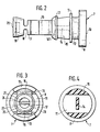
- FIG. 1 shows a part of an electronic control unit in a longitudinal section through the molded part
- FIG. 2 shows a plan view
- FIG. 3 shows a view of the molded part in the direction of arrow III in FIG. 1
- FIG. 4 shows a section through the molded part along the line IV-IV in FIG. 1.
- a circuit board 2 is arranged in the housing 1 of an electronic control unit in a manner known per se and not shown in detail.
- the circuit board 2 is provided with conductor tracks, also not shown.
- the circuit board 2 carries electronic components which are connected to the associated conductor tracks.
- the components include a potentiometer 3, for example a spiral potentiometer with an adjusting screw 4.
- a molded part 7 also protrudes moisture-tight through the bore 6 as an adjusting device on the potentiometer 3.
- the molded part 7 is molded from tough-elastic plastic, for example polyamide.
- the molded part 7 has a screw head-shaped end 8 with a slot 9 on the end face 10.
- a cylindrical sealing section 11 of smaller diameter with an annular groove 12 adjoins the screw head-shaped cylindrical end 8.
- the sealing section 11 goes in two locking hooks 13 and 14 in a narrow web.
- the locking hooks 13 have a shaft 15 with a circular cross-section, which is adapted to the diameter of the bore 6.
- the web 14 is part of a first universal joint, the other part 14 1 formed perpendicular to it merges into an S-shaped intermediate piece 16.
- the end 17 of the intermediate piece 16 forms part of a second universal joint, the other part of which is designed as a narrow web 18 which extends transversely to the end 17 of the intermediate piece 16.
- a rotary body-shaped adjusting section 19 adjoins the web 18.
- the adjusting section 19 has on its face 20 a blind hole-like recess 21 with a funnel-shaped widened edge section 22.
- a blade 24 is formed on the bottom 23 of the recess 21 and extends into the recess 21 like a screwdriver.
- the molded part 7 serves as a one-piece adjusting device for the potentiometer 3, which is inserted into the housing 1 from the outside and is rotatable.
- the molded part 7 is inserted through the housing bore 6 into the fully assembled and moisture-tightly closed electronic control unit.
- the locking hooks 13 are pivoted towards the web 14 until the helical end 8 of the molded part 7 is pressed into the bore 6 until the locking hooks 13 snap automatically onto the inner wall 25 of the housing 1 and lock the molded part 7 on the housing 1.
- a sealing ring 26 is inserted into the annular groove 12 of the molded part 7 in order to keep the molded part 7 in the bore 6 in a moisture-tight manner.
- the molded part 7 is from the outside of the housing 1, for example with a screwdriver, which in the Slot 9 is inserted, rotatable in the bore 6. This makes it possible to turn the adjusting section 19 of the molded part 7 in such a way that its blade 24 engages in the slot of the adjusting screw 4 of the potentiometer 3. This can already happen when the molded part 7 is pressed into the bore 6. The potentiometer 3 is then set by further turning the molded part 7.
- the potentiometer can thus be set reliably free of pressures and tension.
- the resilient S-shaped intermediate piece 16 can also be adjusted in strength in accordance with the pressures to be absorbed, which act on the molded part 7 in the longitudinal direction, so that it is not overloaded,
- the blade can be provided with an insertion aid on the adjusting section, for example,
Landscapes
- Engineering & Computer Science (AREA)
- Microelectronics & Electronic Packaging (AREA)
- Adjustable Resistors (AREA)
- Mounting Components In General For Electric Apparatus (AREA)
- Casings For Electric Apparatus (AREA)
- Details Of Resistors (AREA)
Applications Claiming Priority (2)
| Application Number | Priority Date | Filing Date | Title |
|---|---|---|---|
| DE19843419539 DE3419539A1 (de) | 1984-05-25 | 1984-05-25 | Elektronisches steuergeraet |
| DE3419539 | 1984-05-25 |
Publications (2)
| Publication Number | Publication Date |
|---|---|
| EP0166111A1 true EP0166111A1 (fr) | 1986-01-02 |
| EP0166111B1 EP0166111B1 (fr) | 1989-03-01 |
Family
ID=6236843
Family Applications (1)
| Application Number | Title | Priority Date | Filing Date |
|---|---|---|---|
| EP85105126A Expired EP0166111B1 (fr) | 1984-05-25 | 1985-04-26 | Appareil de commande électronique |
Country Status (4)
| Country | Link |
|---|---|
| US (1) | US4654625A (fr) |
| EP (1) | EP0166111B1 (fr) |
| JP (1) | JPS60261192A (fr) |
| DE (2) | DE3419539A1 (fr) |
Cited By (2)
| Publication number | Priority date | Publication date | Assignee | Title |
|---|---|---|---|---|
| AT397012B (de) * | 1989-09-08 | 1994-01-25 | Vaillant Gmbh | Einstellvorrichtung für ein gerät mit elektrischer regeleinrichtung |
| IT201800004741A1 (it) * | 2018-04-20 | 2019-10-20 | Potenziometro per il controllo di circuiti elettrici |
Families Citing this family (7)
| Publication number | Priority date | Publication date | Assignee | Title |
|---|---|---|---|---|
| JPH0445210Y2 (fr) * | 1986-11-11 | 1992-10-23 | ||
| US5039974A (en) * | 1990-03-19 | 1991-08-13 | Ericsson Ge Mobile Communications Inc. | Protective cap for rotatably-adjustable electronic components |
| DE4203973A1 (de) * | 1992-02-11 | 1993-08-12 | Siemens Ag | Feuchtigkeitsgeschuetzte anordnung mindestens eines elektrischen steuerelementes an einem elektrischen geraet |
| DE4242944C2 (de) * | 1992-12-18 | 2002-04-25 | Bosch Gmbh Robert | Elektrisches Steuergerät |
| US5735179A (en) * | 1995-10-12 | 1998-04-07 | Square D Company | Device for providing axial and spatial misalignment compensation between a rotatable component and a rotating means |
| DE102011089016A1 (de) * | 2011-12-19 | 2013-06-20 | Zf Friedrichshafen Ag | Drehwahlschalter und Verfahren zum Herstellen eines Drehwahlschalters |
| JP5895722B2 (ja) * | 2012-06-07 | 2016-03-30 | オムロン株式会社 | 回転操作部品および電子機器 |
Citations (4)
| Publication number | Priority date | Publication date | Assignee | Title |
|---|---|---|---|---|
| US3373395A (en) * | 1967-08-01 | 1968-03-12 | Simmonds Precision Products | Hermetically sealed multitrimmer potentiometer |
| DE1675403B1 (de) * | 1968-02-29 | 1972-04-27 | Schaltelektronik Veb K | Einrichtung zur Abdichtung eines aus einem Schaltgehaeuse ragenden,radial bewegten Betaetigungsteiles |
| DE2436697A1 (de) * | 1973-08-01 | 1975-02-20 | Bunker Ramo | Stelleinrichtung fuer potentiometer |
| GB2061625A (en) * | 1979-10-25 | 1981-05-13 | Bosch Gmbh Robert | Electronic control unit |
Family Cites Families (1)
| Publication number | Priority date | Publication date | Assignee | Title |
|---|---|---|---|---|
| US3184697A (en) * | 1962-08-28 | 1965-05-18 | Samarius Inc | Hermetically sealed potentiometers |
-
1984
- 1984-05-25 DE DE19843419539 patent/DE3419539A1/de not_active Withdrawn
-
1985
- 1985-04-26 EP EP85105126A patent/EP0166111B1/fr not_active Expired
- 1985-04-26 DE DE8585105126T patent/DE3568529D1/de not_active Expired
- 1985-05-16 US US06/734,852 patent/US4654625A/en not_active Expired - Fee Related
- 1985-05-22 JP JP60108479A patent/JPS60261192A/ja active Pending
Patent Citations (4)
| Publication number | Priority date | Publication date | Assignee | Title |
|---|---|---|---|---|
| US3373395A (en) * | 1967-08-01 | 1968-03-12 | Simmonds Precision Products | Hermetically sealed multitrimmer potentiometer |
| DE1675403B1 (de) * | 1968-02-29 | 1972-04-27 | Schaltelektronik Veb K | Einrichtung zur Abdichtung eines aus einem Schaltgehaeuse ragenden,radial bewegten Betaetigungsteiles |
| DE2436697A1 (de) * | 1973-08-01 | 1975-02-20 | Bunker Ramo | Stelleinrichtung fuer potentiometer |
| GB2061625A (en) * | 1979-10-25 | 1981-05-13 | Bosch Gmbh Robert | Electronic control unit |
Cited By (3)
| Publication number | Priority date | Publication date | Assignee | Title |
|---|---|---|---|---|
| AT397012B (de) * | 1989-09-08 | 1994-01-25 | Vaillant Gmbh | Einstellvorrichtung für ein gerät mit elektrischer regeleinrichtung |
| IT201800004741A1 (it) * | 2018-04-20 | 2019-10-20 | Potenziometro per il controllo di circuiti elettrici | |
| WO2019202562A1 (fr) * | 2018-04-20 | 2019-10-24 | Pizzato Elettrica S.R.L. | Potentiomètre pour commande de circuit électrique |
Also Published As
| Publication number | Publication date |
|---|---|
| EP0166111B1 (fr) | 1989-03-01 |
| DE3419539A1 (de) | 1985-11-28 |
| US4654625A (en) | 1987-03-31 |
| JPS60261192A (ja) | 1985-12-24 |
| DE3568529D1 (en) | 1989-04-06 |
Similar Documents
| Publication | Publication Date | Title |
|---|---|---|
| EP1381782A2 (fr) | Armature servant a relier deux elements | |
| DE19733375B4 (de) | Vorrichtung zur Branderkennung | |
| EP0166111B1 (fr) | Appareil de commande électronique | |
| DE69117867T2 (de) | Endauschlussstück | |
| DE4013810C2 (de) | Drehfeste Verbindung zweier Wellenenden, insbesondere in einem Lenkspindelstrang eines Kraftfahrzeugs | |
| DE1937989B2 (de) | Trimmpotentiometer für elektronische Schaltungen | |
| DE3432856C2 (fr) | ||
| DE3038341A1 (de) | In eine wandoeffnung eines ersten bauteils einsetzbares und ueber eine rastnut mit diesem verrastbares aufnahmeteil | |
| EP0132661B1 (fr) | Déclencheur pour un commutateur sans contact | |
| DE3609366C2 (fr) | ||
| DE3014875A1 (de) | Kontakttraeger | |
| DE68917659T2 (de) | Kugelzapfenzusammenbau. | |
| EP0119952B1 (fr) | Dispositif de verrouillage pour un connecteur enfichable | |
| DE3423106A1 (de) | Abstandhalter fuer elektrische leiter, insbesondere fuer blitzschutzleiter | |
| DE8415992U1 (de) | Elektronisches Steuergerät | |
| DE29714671U1 (de) | Lochscheibe | |
| DE3323861A1 (de) | Einstellvorrichtung fuer die vorspannkraft einer feder | |
| EP0093236B1 (fr) | Fiche pour appareil | |
| DE19624660A1 (de) | Elektrischer Verbinder | |
| DE2852913C2 (de) | Verstellschraube | |
| EP0795185B1 (fr) | Selecteur rotatif, notamment selecteur de changement de vitesse pour vehicules a moteur | |
| DE3922237C2 (fr) | ||
| DE3637350C2 (fr) | ||
| EP0540955A1 (fr) | Dispositif pour fixer un aimant permanent en forme de barre | |
| DE3542086C2 (fr) |
Legal Events
| Date | Code | Title | Description |
|---|---|---|---|
| PUAI | Public reference made under article 153(3) epc to a published international application that has entered the european phase |
Free format text: ORIGINAL CODE: 0009012 |
|
| 17P | Request for examination filed |
Effective date: 19850426 |
|
| AK | Designated contracting states |
Designated state(s): DE FR GB IT SE |
|
| 17Q | First examination report despatched |
Effective date: 19870211 |
|
| GRAA | (expected) grant |
Free format text: ORIGINAL CODE: 0009210 |
|
| AK | Designated contracting states |
Kind code of ref document: B1 Designated state(s): DE FR GB IT SE |
|
| GBT | Gb: translation of ep patent filed (gb section 77(6)(a)/1977) | ||
| REF | Corresponds to: |
Ref document number: 3568529 Country of ref document: DE Date of ref document: 19890406 |
|
| ET | Fr: translation filed | ||
| ITF | It: translation for a ep patent filed | ||
| PLBE | No opposition filed within time limit |
Free format text: ORIGINAL CODE: 0009261 |
|
| STAA | Information on the status of an ep patent application or granted ep patent |
Free format text: STATUS: NO OPPOSITION FILED WITHIN TIME LIMIT |
|
| 26N | No opposition filed | ||
| ITTA | It: last paid annual fee | ||
| PGFP | Annual fee paid to national office [announced via postgrant information from national office to epo] |
Ref country code: DE Payment date: 19920629 Year of fee payment: 8 |
|
| PGFP | Annual fee paid to national office [announced via postgrant information from national office to epo] |
Ref country code: SE Payment date: 19920710 Year of fee payment: 8 |
|
| PGFP | Annual fee paid to national office [announced via postgrant information from national office to epo] |
Ref country code: GB Payment date: 19920717 Year of fee payment: 8 |
|
| PGFP | Annual fee paid to national office [announced via postgrant information from national office to epo] |
Ref country code: FR Payment date: 19920824 Year of fee payment: 8 |
|
| PG25 | Lapsed in a contracting state [announced via postgrant information from national office to epo] |
Ref country code: GB Effective date: 19930426 |
|
| PG25 | Lapsed in a contracting state [announced via postgrant information from national office to epo] |
Ref country code: SE Effective date: 19930427 |
|
| GBPC | Gb: european patent ceased through non-payment of renewal fee |
Effective date: 19930426 |
|
| PG25 | Lapsed in a contracting state [announced via postgrant information from national office to epo] |
Ref country code: FR Effective date: 19931229 |
|
| PG25 | Lapsed in a contracting state [announced via postgrant information from national office to epo] |
Ref country code: DE Effective date: 19940101 |
|
| REG | Reference to a national code |
Ref country code: FR Ref legal event code: ST |
|
| EUG | Se: european patent has lapsed |
Ref document number: 85105126.8 Effective date: 19931110 |