EP0166136A2 - Méthode et dispositif de comptage optique de corps minuscules - Google Patents
Méthode et dispositif de comptage optique de corps minuscules Download PDFInfo
- Publication number
- EP0166136A2 EP0166136A2 EP85105661A EP85105661A EP0166136A2 EP 0166136 A2 EP0166136 A2 EP 0166136A2 EP 85105661 A EP85105661 A EP 85105661A EP 85105661 A EP85105661 A EP 85105661A EP 0166136 A2 EP0166136 A2 EP 0166136A2
- Authority
- EP
- European Patent Office
- Prior art keywords
- bodies
- light
- individual
- information
- measuring space
- Prior art date
- Legal status (The legal status is an assumption and is not a legal conclusion. Google has not performed a legal analysis and makes no representation as to the accuracy of the status listed.)
- Withdrawn
Links
Images

Classifications
-
- A—HUMAN NECESSITIES
- A01—AGRICULTURE; FORESTRY; ANIMAL HUSBANDRY; HUNTING; TRAPPING; FISHING
- A01C—PLANTING; SOWING; FERTILISING
- A01C7/00—Sowing
- A01C7/08—Broadcast seeders; Seeders depositing seeds in rows
- A01C7/10—Devices for adjusting the seed-box ; Regulation of machines for depositing quantities at intervals
- A01C7/102—Regulating or controlling the seed rate
- A01C7/105—Seed sensors
-
- G—PHYSICS
- G06—COMPUTING OR CALCULATING; COUNTING
- G06M—COUNTING MECHANISMS; COUNTING OF OBJECTS NOT OTHERWISE PROVIDED FOR
- G06M1/00—Design features of general application
- G06M1/08—Design features of general application for actuating the drive
- G06M1/10—Design features of general application for actuating the drive by electric or magnetic means
- G06M1/101—Design features of general application for actuating the drive by electric or magnetic means by electro-optical means
-
- G—PHYSICS
- G06—COMPUTING OR CALCULATING; COUNTING
- G06M—COUNTING MECHANISMS; COUNTING OF OBJECTS NOT OTHERWISE PROVIDED FOR
- G06M3/00—Counters with additional facilities
-
- G—PHYSICS
- G06—COMPUTING OR CALCULATING; COUNTING
- G06M—COUNTING MECHANISMS; COUNTING OF OBJECTS NOT OTHERWISE PROVIDED FOR
- G06M7/00—Counting of objects carried by a conveyor
-
- G—PHYSICS
- G01—MEASURING; TESTING
- G01N—INVESTIGATING OR ANALYSING MATERIALS BY DETERMINING THEIR CHEMICAL OR PHYSICAL PROPERTIES
- G01N15/00—Investigating characteristics of particles; Investigating permeability, pore-volume or surface-area of porous materials
- G01N15/10—Investigating individual particles
- G01N15/14—Optical investigation techniques, e.g. flow cytometry
- G01N15/1429—Signal processing
- G01N15/1433—Signal processing using image recognition
-
- G—PHYSICS
- G01—MEASURING; TESTING
- G01N—INVESTIGATING OR ANALYSING MATERIALS BY DETERMINING THEIR CHEMICAL OR PHYSICAL PROPERTIES
- G01N15/00—Investigating characteristics of particles; Investigating permeability, pore-volume or surface-area of porous materials
- G01N15/10—Investigating individual particles
- G01N15/14—Optical investigation techniques, e.g. flow cytometry
- G01N2015/1486—Counting the particles
-
- G—PHYSICS
- G01—MEASURING; TESTING
- G01N—INVESTIGATING OR ANALYSING MATERIALS BY DETERMINING THEIR CHEMICAL OR PHYSICAL PROPERTIES
- G01N15/00—Investigating characteristics of particles; Investigating permeability, pore-volume or surface-area of porous materials
- G01N15/10—Investigating individual particles
- G01N15/14—Optical investigation techniques, e.g. flow cytometry
- G01N2015/1497—Particle shape
Definitions
- the invention relates to a method for the optical counting of seeds, fertilizers and other bodies used in agriculture, in which the bodies to be counted pass through a measuring space and thereby interrupt the beam path between a light emitter and a light detector.
- the invention further relates to an apparatus for performing such a method, wherein a light emitter is arranged on one side of the measuring space and a light receiver is arranged on the opposite side.
- Such a method is e.g. known from DE-PS 25 34 130.
- bodies namely seeds to be sown
- the light barrier then generates pulses for each interruption in its beam path.
- the number of impulses matches the number of bodies that have passed through, provided that the bodies pass the light barrier individually and one after the other.
- errors can occur because also in this case, only one count is emitted by the light barrier.
- the invention is therefore based on the object To improve the method and a device of the type mentioned at the outset such that a plurality of bodies located in the measuring space at the same time are also detected individually, so that overall a more accurate count is possible than is the case with the known method.
- This object is achieved in that in the measuring space with the aid of light rays generating an optical grid, individual location points at which the beam path is interrupted by bodies passing through the optical grid are recorded in successive scanning cycles and recorded as one or more bodies describing information and that the information describing the bodies of the individual scanning cycles obtained is then compared with one another, and that counting signals corresponding to the number of individual bodies passing through are then derived from the variations in the interrupting location points that were found in the comparison.
- the measuring space is viewed differentially, ie at individual points or areas. This makes it possible to determine whether the light beam is interrupted in these individually examined areas or whether it is continuous. If it is ascertained that the special light beam illuminating this point or region is interrupted at a point under consideration, this information is interpreted to mean that a body or part of a body interrupts the light beam there.
- the areas in which it is determined in a first scanning cycle that they interrupt the light path are therefore recorded as body-describing information, for example in a data memory.
- the individual areas or location points are scanned again and the In obtained thereby Formations compared with the information obtained in the previous cycle. This opens up the possibility of tracking the passage of the individual bodies in time and space. This also makes it possible to detect several bodies that are located at the same time but at different locations in the measuring room.
- the method according to the invention can be carried out with a one-dimensional view, ie the light rays only emanate from one side and thereby produce a line screen, or also with a three-dimensional view, in which light rays would produce a cubic screen, it has proven to be advantageous proven to look at the measuring space from two sides, ie to use an optical, two-dimensional grid of intersecting light beams.
- a two-dimensional grid makes it possible to also include those bodies that pass the measurement space behind a first body in the viewing direction. It is then measured for the evaluation of the body descriptive information favorable if the light beams intersect at an angle of 90 0th
- the information of the individual scanning cycles is processed in parallel, because this gives a faster possibility of evaluation than is possible with serial processing.
- the location points obtained in the individual cycles are added in order to obtain a volume measure and that the body volume obtained is compared with a minimum and a maximum value and that a count signal is only emitted if if the volume measure obtained is within these extreme values.
- These measures only accept bodies in the defined tolerance range. Bodies with other dimensions are excluded from the count, so that foreign bodies in particular do not lead to errors in the count.
- the extreme values can be selected depending on the volume data of a certain number of bodies obtained.
- the method according to the invention can be carried out with a device mentioned at the outset, in which discrete light receivers according to the invention, one separate detection-enabling reception cells are used, so that several elementary light barriers are formed within the measuring room, the output signals of which are fed to an evaluation circuit in which they are processed cyclically.
- the individual elementary light barriers form a light grid in the measuring room, so that it can be determined for individual areas within the measuring room whether there is a body or not.
- two opposing light emitter lines and light receiver lines arranged at right angles to one another are provided, so that the rays emanating from the light emitter lines cross and form an optical grid pattern and that the evaluation circuit comprises a multiplier in which the information received as logic signals from the individual receive cells of the X line is multiplied by that of the Y line, so that a matrix Z is formed for each scanning cycle, which is characteristic of how the measurement space is seen by the two receive lines.
- the locations at which the individual bodies are present can be seen, e.g. in which a logical 1 instead of a 0 is registered.
- the evaluation circuit comprises a scanning device in which the rows of the Z matrix are scanned and the positions corresponding to each 0/1 change or 1/0 change are noted in a data field. This allows the current position of the left edge of a body and the right edge of a body and thus the body itself to be determined.
- the evaluation circuit further comprises a comparison circuit in which the data of the lines are related to one another, then it can be determined in a chronological sequence whether or how a determined body-describing data field changes. The information about the number of bodies can then be determined from this. Further features and details of the invention can be found in the subclaims, the description and the drawing.
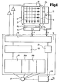
- FIG. 1, 2 denotes a measuring space, through which individual bodies, such as seed grains of a seed drill, fall perpendicularly to the plane of representation in order to be counted.
- a light-emitting diode row 4 with an opposite receiving diode row 6 and at an angle of 90 ° to another LED row 10 with an associated, opposite receiving diode row 8 are arranged in a horizontal plane at the edge of the measuring space.
- the receiving diode lines 6 and 8 each consist of individual light receiving cells arranged side by side D 1 to D n or Dl 'to Dn', so that intersecting elementary light barriers which form a two-dimensional grid monitor the measuring space.
- the selective signals detected at the individual receiving cells D1 to Dn or D 1 'to D n' are amplified in assigned amplifier devices 12 and 14 and converted into logic signals. For example, a receiving diode cell that receives a light beam is assigned a logical zero and a cell that does not receive a light beam is assigned a logical one.
- the logic signals obtained are processed in an evaluation device 16, which will be described in more detail below.
- the line information is first recorded in a scanning device 18, this being done in such a way that the individual states of the light receiving cells D1 to D n or D1 'to Dn' are determined as they exist at a certain point in time T.
- the data sampling device 18 is connected to a time circuit 20.
- the data is forwarded to a data buffer 22, which stores the signals which result in a agreed time both in the receive diode row 6 (hereinafter called the Y line) and in the receive diode row 8 (hereinafter referred to as the X line);
- a data buffer 22 stores the signals which result in a agreed time both in the receive diode row 6 (hereinafter called the Y line) and in the receive diode row 8 (hereinafter referred to as the X line);
- snapshots of the plane crossed by the beams are taken, as seen by the receiving diode lines X and Y at a certain time.
- Such image line recordings are carried out cyclically in succession at certain time intervals and are each stored in data buffers.
- the individual lines are then fed from the data buffer to the evaluation circuit 26, in which the information obtained through the different cycles is related to one another, so that the number of bodies passing through the measuring space can be determined.
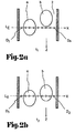
- the schematic diagram 2a represents a snapshot at time t, as it is projected as a snapshot of the light beams extending perpendicular to the plane of the drawing and extending in the Y direction onto the assigned reception diode row, the individual reception cells D1 to Dn of which are indicated as circles.
- the receive diode row shown At time t 1 (cf. FIG. 2a), the receive diode row shown generates the sequence of logical signals listed there in table 1 for the Y row at time t 1 .
- table 1 For the X line, what can be seen in the drawing not shown, a corresponding sequence of logical signals is also obtained.
- both grains At a time t; (cf. FIG. 2b), both grains have fallen somewhat lower, so that, which is again only shown for the Y line in the figures, the sequences resulting in the table at time t 2 for the entire Y or X Let line get.
- the values thus obtained for the X or Y lines are then multiplied with one another in the evaluation computer. This results in a matrix Z for each row X, Y.
- the matrices for the measurements at times t 1 -t 3 are shown below. It can be seen that the matrices represent a plan view as seen by the two receiver diode rows 6 and 8 at successive times.
- the rows of the Z matrix are then scanned.
- a zero / one change which corresponds to the left edge of a body
- the current position of the body is noted in a data field assigned to the body. From here, all ones information for a one / zero change, which corresponds to the left edge of a body, is counted.
- the limit position of the body is then noted for comparison with the next line.
- body descriptive information is built up for each body found or data fields that provide information about the size of the body and the contours.
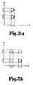
- the two-dimensional view makes it possible to recognize two bodies lying one behind the other with respect to one viewing direction and adjacent to one another with respect to the other viewing direction (cf. FIG. 3a). However, as is shown in a sketchy manner in FIG.
- the evaluation in the evaluation circuit first assumes the premise that if a body consisting of two or several bodies arise, the cause of which lies in a second body. With the measurement result obtained, the dummy bodies will disappear when the end of the first body is reached. In this case only one body is counted.
- Such an additional analysis possibility consists in that before the output signal indicating a body is generated, a volume measure or body volume obtained by adding the row values in the matrix is taken, which is compared with a minimum and a maximum value. In this case, only those bodies are accepted that lie in the area in between.
- the limit values min ⁇ and max. can be selected from the obtained volume data of a certain number of bodies.
- the optical elements can or should be cleaned.
- One way of doing this is shown in FIGS. 4 and 5.
- the light-emitting diode lines and receiving diode lines are accommodated in a rotatable glass envelope 30 there.
- a drive device 32 is provided at diagonally opposite corners, which rotates the glass tubes in a suitable manner around the receive diode rows or transmit diode rows.
- a scraper 34 (see FIG. 5) grazes the surface of the glass tubes and cleans them when they are driven in a circle.
Landscapes
- Life Sciences & Earth Sciences (AREA)
- Physics & Mathematics (AREA)
- General Physics & Mathematics (AREA)
- Engineering & Computer Science (AREA)
- Theoretical Computer Science (AREA)
- Soil Sciences (AREA)
- Environmental Sciences (AREA)
- Geophysics And Detection Of Objects (AREA)
- Investigating Or Analysing Materials By Optical Means (AREA)
- Time Recorders, Dirve Recorders, Access Control (AREA)
Applications Claiming Priority (2)
| Application Number | Priority Date | Filing Date | Title |
|---|---|---|---|
| DE19843419883 DE3419883A1 (de) | 1984-05-28 | 1984-05-28 | Verfahren und vorrichtung zum optischen zaehlen kleiner koerperchen |
| DE3419883 | 1984-05-28 |
Publications (2)
| Publication Number | Publication Date |
|---|---|
| EP0166136A2 true EP0166136A2 (fr) | 1986-01-02 |
| EP0166136A3 EP0166136A3 (fr) | 1987-05-13 |
Family
ID=6237055
Family Applications (1)
| Application Number | Title | Priority Date | Filing Date |
|---|---|---|---|
| EP85105661A Withdrawn EP0166136A3 (fr) | 1984-05-28 | 1985-05-08 | Méthode et dispositif de comptage optique de corps minuscules |
Country Status (3)
| Country | Link |
|---|---|
| US (1) | US4675520A (fr) |
| EP (1) | EP0166136A3 (fr) |
| DE (1) | DE3419883A1 (fr) |
Cited By (6)
| Publication number | Priority date | Publication date | Assignee | Title |
|---|---|---|---|---|
| EP0298549A3 (en) * | 1987-07-02 | 1989-07-26 | C. Van Der Lely N.V. | A machine for spreading material, such as fertilizer |
| DE3906578A1 (de) * | 1988-03-03 | 1989-09-07 | Klaeger Elektronik M | Verfahren und vorrichtung zum besetzen von in reihenweise nebeneinander und hintereinander auf paletten angeordneten pflanznaepfchen mit kleinkoernigem saatgut |
| EP1332793A1 (fr) * | 2002-02-04 | 2003-08-06 | Pet International Trading Gmbh | Procédé et appareil pour le dosage de particules |
| EP1566089A1 (fr) | 2004-02-19 | 2005-08-24 | Amazonen-Werke H. Dreyer GmbH & Co. KG | Dispositif de comptage optique de corps minuscules |
| EP1662247A1 (fr) * | 2004-11-24 | 2006-05-31 | Amazonen-Werke H. Dreyer GmbH & Co. KG | Procédé destiné à la détermination de la forme et/ou la taille d'une particule de produit agricole |
| EP1726200A1 (fr) * | 2005-05-27 | 2006-11-29 | Amazonen-Werke H. Dreyer GmbH & Co. KG | Procédé pour la détermination de la qualité de produits agricoles en vrac |
Families Citing this family (34)
| Publication number | Priority date | Publication date | Assignee | Title |
|---|---|---|---|---|
| GB8516181D0 (en) * | 1985-06-26 | 1985-07-31 | Unilever Plc | Metering flowable particulates |
| DE3733878A1 (de) * | 1987-10-07 | 1989-04-27 | Soric Ind Electronic Di El Gmb | Geraet zur materialflusserfassung |
| GB8726478D0 (en) * | 1987-11-12 | 1987-12-16 | Unilever Plc | Metering apparatus |
| US4984889A (en) * | 1989-03-10 | 1991-01-15 | Pacific Scientific Company | Particle size measuring system with coincidence detection |
| US5177470A (en) * | 1990-08-06 | 1993-01-05 | Vansco Electronic Ltd. | Sensor device for particles in an air stream |
| US5313508A (en) * | 1991-12-23 | 1994-05-17 | Batching Systems, Inc. | Method of and apparatus for detecting and counting articles |
| US5454016A (en) * | 1991-12-23 | 1995-09-26 | Batching Systems Inc. | Method and apparatus for detecting and counting articles |
| US5635911A (en) * | 1995-05-11 | 1997-06-03 | Dickey-John Corporation | Apparatus and method for monitoring an article dispensing device such as a seed planter and the like |
| GB2328051B (en) * | 1995-05-16 | 1999-11-10 | Semelab Plc | Counting and batching apparatus |
| US6073427A (en) * | 1998-06-11 | 2000-06-13 | Nichols; Stephen W. | Method and apparatus for counting crops |
| US6380503B1 (en) * | 2000-03-03 | 2002-04-30 | Daniel G. Mills | Apparatus and method using collimated laser beams and linear arrays of detectors for sizing and sorting articles |
| EP1531777A1 (fr) * | 2002-07-29 | 2005-05-25 | Mckesson Automation Systems, Inc. | Procede de distribution et de comptage d'articles et dispositif associe |
| US6836527B1 (en) | 2004-02-06 | 2004-12-28 | Batching Systems, Inc. | Method and apparatus for detecting and counting articles |
| SE0400932L (sv) * | 2004-04-06 | 2005-10-07 | Vaederstad Verken Ab | Anordning och förfarande för fröräkning hos såmaskin |
| SE0400933L (sv) * | 2004-04-06 | 2005-03-01 | Vaederstad Verken Ab | Anordning och förfarande för fröräkning hos såmaskin |
| DE102005005557C5 (de) * | 2005-02-07 | 2019-03-14 | Pöttinger Landtechnik Gmbh | Vorrichtung zur Steuerung und/oder Regelung einer Landmaschine mittels einer Bilderfassungs- und -verarbeitungseinrichtung |
| DE102005048744A1 (de) * | 2005-10-10 | 2007-04-12 | Amazonen-Werke H. Dreyer Gmbh & Co. Kg | Vorrichtung zum optischen Zählen kleiner Körnerchen |
| DE202006007875U1 (de) | 2006-05-15 | 2007-09-20 | Big Dutchman International Gmbh | Eierzählsensor |
| US8213014B1 (en) | 2007-07-21 | 2012-07-03 | Werner Willemse | High speed counter and inspector for medicament and other small objects |
| US8618465B2 (en) | 2008-11-13 | 2013-12-31 | Deere & Company | Seed sensor system and method for improved seed count and seed spacing |
| US20100116974A1 (en) * | 2008-11-13 | 2010-05-13 | Liu James Z | Seed Sensor System And Method For Improved Seed Count And Seed Spacing |
| CN101799885B (zh) * | 2010-03-23 | 2013-03-13 | 上海慧森电气有限公司 | 块状物料计数器及计数方法 |
| FR2987922B1 (fr) * | 2012-03-06 | 2014-04-18 | Commissariat Energie Atomique | Procede et dispositif de comptage d'objets |
| BR112015004356B1 (pt) * | 2012-08-27 | 2022-03-15 | Dickey-John | Dispositivo de contagem de semente, sistema de detecção de partícula e método para detectar as sementes em um sistema de deposição de semente |
| EA028198B1 (ru) | 2012-10-24 | 2017-10-31 | Биг Дачман Интернэшнл Гмбх | Конвейер и способ транспортировки продуктов жизнедеятельности животных в сельскохозяйственном предприятии |
| DE102014106777A1 (de) * | 2014-05-14 | 2015-11-19 | Amazonen-Werke H. Dreyer Gmbh & Co. Kg | Schleuderdüngerstreuer und Verfahren für einen Schleuderdüngerstreuer |
| DE202014007282U1 (de) | 2014-09-12 | 2015-12-16 | Big Dutchman International Gmbh | Dosiervorrichtung |
| DE102015105790A1 (de) | 2015-04-15 | 2016-10-20 | Lemken Gmbh & Co. Kg | Landwirtschaftliche Einzelkornsämaschine |
| US9661805B1 (en) | 2015-12-29 | 2017-05-30 | Ball Horticultural Company | Seed sowing system and method of use |
| US9867328B2 (en) * | 2016-01-08 | 2018-01-16 | Deere & Company | Systems for monitoring seeds and methods thereof |
| DE202016105370U1 (de) | 2016-09-27 | 2018-01-02 | Big Dutchman International Gmbh | Fütterungsvorrichtung für Geflügeltiere |
| JP2019100988A (ja) * | 2017-12-08 | 2019-06-24 | 株式会社島津製作所 | 粒子画像解析装置及び粒子画像解析方法 |
| AU2020245261B2 (en) * | 2019-03-22 | 2025-01-23 | Precision Planting Llc | Particle counting apparatus, systems and methods |
| CN113784285B (zh) * | 2021-09-09 | 2023-06-27 | 平安好医投资管理有限公司 | 基于蓝牙设备的智能呼叫方法、装置、电子设备及介质 |
Family Cites Families (13)
| Publication number | Priority date | Publication date | Assignee | Title |
|---|---|---|---|---|
| US3395269A (en) * | 1965-03-22 | 1968-07-30 | Delta Engineering Corp | Article counting machine with means for preventing miscount of overlapping and irregularly shaped articles |
| FR1458715A (fr) * | 1965-10-07 | 1966-03-04 | Fairbanks Morse | Système pour la détermination automatique des dimensions et du poids de dirers objcts, utilisable notamment pour leur manutention |
| US3692980A (en) * | 1971-02-25 | 1972-09-19 | Ncr Co | Counter for variable size and shape objects |
| US3774040A (en) * | 1972-05-10 | 1973-11-20 | Lauer G | Photoelectric system for grading objects according to size |
| US4183013A (en) * | 1976-11-29 | 1980-01-08 | Coulter Electronics, Inc. | System for extracting shape features from an image |
| US4203029A (en) * | 1978-03-06 | 1980-05-13 | Artek Systems Corporation | Automatic object counter |
| US4163507A (en) * | 1978-03-20 | 1979-08-07 | International Tapetronics Corporation | Optical seed sensor for a seed planter monitor |
| US4384201A (en) * | 1978-04-24 | 1983-05-17 | Carroll Manufacturing Corporation | Three-dimensional protective interlock apparatus |
| FR2458804A1 (fr) * | 1979-06-05 | 1981-01-02 | Hanusse Gerard | Dispositif de detection et de mesure de corps liquides ou solides en mouvement |
| US4307390A (en) * | 1979-11-07 | 1981-12-22 | Dickey-John Corporation | Corn and soybean sensor |
| US4371253A (en) * | 1981-01-19 | 1983-02-01 | Eastman Kodak Company | Color electrophotographic copier |
| US4490801A (en) * | 1982-07-06 | 1984-12-25 | Hagan Engineering, Inc. | Article sizing apparatus and container filling system employing the same |
| US4589079A (en) * | 1983-04-14 | 1986-05-13 | Ficht Gmbh | Evaluation circuit for the signals from an array of N photoconductors which are successively scanned in a fast rhythm |
-
1984
- 1984-05-28 DE DE19843419883 patent/DE3419883A1/de not_active Withdrawn
-
1985
- 1985-05-08 EP EP85105661A patent/EP0166136A3/fr not_active Withdrawn
- 1985-05-24 US US06/738,155 patent/US4675520A/en not_active Expired - Fee Related
Cited By (6)
| Publication number | Priority date | Publication date | Assignee | Title |
|---|---|---|---|---|
| EP0298549A3 (en) * | 1987-07-02 | 1989-07-26 | C. Van Der Lely N.V. | A machine for spreading material, such as fertilizer |
| DE3906578A1 (de) * | 1988-03-03 | 1989-09-07 | Klaeger Elektronik M | Verfahren und vorrichtung zum besetzen von in reihenweise nebeneinander und hintereinander auf paletten angeordneten pflanznaepfchen mit kleinkoernigem saatgut |
| EP1332793A1 (fr) * | 2002-02-04 | 2003-08-06 | Pet International Trading Gmbh | Procédé et appareil pour le dosage de particules |
| EP1566089A1 (fr) | 2004-02-19 | 2005-08-24 | Amazonen-Werke H. Dreyer GmbH & Co. KG | Dispositif de comptage optique de corps minuscules |
| EP1662247A1 (fr) * | 2004-11-24 | 2006-05-31 | Amazonen-Werke H. Dreyer GmbH & Co. KG | Procédé destiné à la détermination de la forme et/ou la taille d'une particule de produit agricole |
| EP1726200A1 (fr) * | 2005-05-27 | 2006-11-29 | Amazonen-Werke H. Dreyer GmbH & Co. KG | Procédé pour la détermination de la qualité de produits agricoles en vrac |
Also Published As
| Publication number | Publication date |
|---|---|
| DE3419883A1 (de) | 1985-11-28 |
| US4675520A (en) | 1987-06-23 |
| EP0166136A3 (fr) | 1987-05-13 |
Similar Documents
| Publication | Publication Date | Title |
|---|---|---|
| DE3419883A1 (de) | Verfahren und vorrichtung zum optischen zaehlen kleiner koerperchen | |
| DE2403270C2 (de) | Vorrichtung zur Erzeugung von Positionssignalen eines auf einer Abtastfläche bewegbaren Gegenstandes | |
| DE3688823T2 (de) | Verfahren zum dreidimensionalen messen von gegenständen. | |
| DE69023107T2 (de) | Verfahren und Vorrichtung zur Teilchenanalyse. | |
| DE2937335C2 (de) | Verfahren und Vorrichtung zur optischen Prüfung von Gegenständen | |
| DE2307722A1 (de) | Verfahren und geraet zur flaechenmessung ohne beruehrung | |
| EP1672359B1 (fr) | Méthode pour mesurer le spectre de transfert d'impulsion de quanta de rayons x diffractés élastiquement | |
| DE3506328C2 (de) | Verfahren zum Korrigieren von Koinzidenzfehlern bei in einer Teilchenanalysieranordnung erhaltenen Parameterdaten von Teilchen, sowie Vorrichtung zur Durchführung des Verfahrens | |
| DE6808865U (de) | Gammastrahlen-anzeigegeraet | |
| EP0271723A1 (fr) | Dispositif de balayage à rayons X | |
| DE2723329A1 (de) | Vorrichtung zum pruefen von oberflaechen | |
| DE10046352A1 (de) | Verfahren und Vorrichtung für das Durchführen einer Korrektur einer Emissionskontamination und eines Totzeitverlustes in einem medizinischen Bilderzeugungssystem | |
| DE2702009A1 (de) | Radiographisches geraet | |
| DE1956377A1 (de) | Tomographische Strahlenkamera | |
| DE2331545A1 (de) | Verfahren und vorrichtung zur bestimmung der laenge von stapelfasern | |
| DE10156629A1 (de) | Anordnung von Steuerelementen | |
| DE3401475C2 (fr) | ||
| EP0443137A2 (fr) | Procédé pour la mesure tri-dimensionnelle optique d'objets et dispositif pour mettre en oeuvre le procÀ©dé | |
| DE2454574C2 (fr) | ||
| EP0525733A1 (fr) | Procédé et dispositif de détection de la trajectoire d'un projectile | |
| EP0072511B1 (fr) | Dispositif de détermination de la position dans un plan de mesure du point d'intersection entre ce plan et la trajectoire d'un objet | |
| DE3638325C2 (fr) | ||
| WO2015188810A1 (fr) | Procédé de détermination des lieux d'origine de signaux de rayonnement dans une zone à mesurer et appareil de mesure permettant de détecter simultanément des événements radiatifs de radionucléides qui se désintègrent dans la zone à mesurer | |
| DE2526110B2 (de) | Vorrichtung zum Messen kleiner Auslenkungen eines Lichtbündels | |
| DE2314578A1 (de) | Verfahren und vorrichtung zur korrektur koinzidenzbedingter zaehlfehler bei teilchenanalysatoren |
Legal Events
| Date | Code | Title | Description |
|---|---|---|---|
| PUAI | Public reference made under article 153(3) epc to a published international application that has entered the european phase |
Free format text: ORIGINAL CODE: 0009012 |
|
| AK | Designated contracting states |
Designated state(s): AT BE CH DE FR GB IT LI LU NL SE |
|
| PUAL | Search report despatched |
Free format text: ORIGINAL CODE: 0009013 |
|
| AK | Designated contracting states |
Kind code of ref document: A3 Designated state(s): AT BE CH DE FR GB IT LI LU NL SE |
|
| STAA | Information on the status of an ep patent application or granted ep patent |
Free format text: STATUS: THE APPLICATION IS DEEMED TO BE WITHDRAWN |
|
| 18D | Application deemed to be withdrawn |
Effective date: 19870602 |
|
| RIN1 | Information on inventor provided before grant (corrected) |
Inventor name: HARRSEN, JAN, DIPL.-ING. Inventor name: GATTERMANN, BERND, DIPL.-ING. Inventor name: GROSSE-SCHARMANN, FRANZ, DR. DIPL.-ING. |