EP0166209A2 - Appareil de contrôle des mesures de protection dans des installations électriques - Google Patents
Appareil de contrôle des mesures de protection dans des installations électriques Download PDFInfo
- Publication number
- EP0166209A2 EP0166209A2 EP85106334A EP85106334A EP0166209A2 EP 0166209 A2 EP0166209 A2 EP 0166209A2 EP 85106334 A EP85106334 A EP 85106334A EP 85106334 A EP85106334 A EP 85106334A EP 0166209 A2 EP0166209 A2 EP 0166209A2
- Authority
- EP
- European Patent Office
- Prior art keywords
- measuring
- plug
- measuring device
- contact
- switch
- Prior art date
- Legal status (The legal status is an assumption and is not a legal conclusion. Google has not performed a legal analysis and makes no representation as to the accuracy of the status listed.)
- Granted
Links
Images


Classifications
-
- G—PHYSICS
- G01—MEASURING; TESTING
- G01R—MEASURING ELECTRIC VARIABLES; MEASURING MAGNETIC VARIABLES
- G01R19/00—Arrangements for measuring currents or voltages or for indicating presence or sign thereof
- G01R19/145—Indicating the presence of current or voltage
-
- G—PHYSICS
- G01—MEASURING; TESTING
- G01R—MEASURING ELECTRIC VARIABLES; MEASURING MAGNETIC VARIABLES
- G01R15/00—Details of measuring arrangements of the types provided for in groups G01R17/00 - G01R29/00, G01R33/00 - G01R33/26 or G01R35/00
- G01R15/08—Circuits for altering the measuring range
- G01R15/09—Autoranging circuits
Definitions
- the invention relates to a measuring device mentioned in the preamble of claim 1.
- the measuring lines of the device are connected to a three-pin measuring plug, which can be plugged into the earthed sockets.
- the measurement itself is not three-pole, but only two-pole, ie of the three poles of the measuring plug consisting of protective contact and two plug pins, only two are required as measuring contacts which absorb potential differences between certain conductors of the network.
- measurements must be made between the phase conductor L and the protective conductor PE or between the phase conductor L and the neutral conductor N.
- the checking of the protective measures is not only limited to sockets, but must of course also be able to be carried out directly on the conductors in systems.
- the three-pin measuring plug is unsuitable for contacting, so that it is replaced in known measuring devices by three measuring lines with banana plugs or connected to them by an adapter. Again, it is annoying that the three banana plugs must be carefully monitored for polarity.
- a measured variable for example the network loop resistance and the resulting short-circuit current
- several individual measurements must be carried out in succession, in which the measuring device must be operated.
- the measuring device For operation, as in the "de / der elektromeister + deutsches elektrohandtechnik" booklet 3/87, pages 148 to 152 Insulation measuring device described, several switches or buttons required.
- the object of the invention is to design a measuring device of the type mentioned in the preamble of claim 1 so that when connecting the measuring lines of the measuring device to the electrical system to be examined there is no need to pay attention to the polarity (phase) and to carry out the measurement quickly and can be done easily without having to operate the control elements provided on the measuring device during the measurement.
- the automatic measuring system ensures that the three correct poles of the measuring plug are always selected as measuring contacts, there is not only the advantage that when plugging the measuring plug into a socket, the phase position no longer has to be taken into account, but above all also that a three-pole connection can be made from the three-pole at will.
- the measuring plug is not suitable for contacting, it is therefore not necessary to connect three measuring lines to the measuring plug, but two measuring lines with connected banana plugs or measuring tips are sufficient.
- Another advantage of the measuring device according to the invention is that the hand no longer has to be removed from the measuring plug in order to carry out a measurement to the end, but that the movement of a finger is sufficient to actuate the hand switch.
- the automatic measuring system in conjunction with the measured variable switch ensures that the pole pin becomes the measuring contact that comes into contact with the phase, while the pole pin on the neutral conductor or the protective contact changes, if necessary serve as measuring contact.
- a contact adapter which can be placed on the measuring plug is designed as a plug-in pot to which two measuring tips are attached. It is important that one of the two measuring tips is firmly connected to the plug pot, so that the measuring plug can be held in one hand with the attached contact adapter.
- a second measuring tip of the contact adapter is connected to the socket via a measuring cable and can be held in the other hand. A safe measurement on free lines can thus be carried out with both measuring tips, the measuring device being operated via the hand switch.
- a further embodiment of the subject matter of the invention provides that the measuring plug can be used not only to measure sockets with external protective contacts, but also those which are provided with a protective contact pin. This also results in simple contacting of the measuring tip fixedly mounted on the plug pot, which is provided with a protective contact pin which engages in a protective contact socket of the measuring plug.
- phase adjustment that can be achieved by automatic switching is not advantageous in all cases.
- the position of the phase relative to the protective contact pin is mandatory.
- An automatic phase adjustment is undesirable here, since it would prevent a control of the phase position and no measurement between neutral conductor N and protective conductor PE would be possible.
- a voltage measuring range is therefore provided, in which the automatic phase adjustment is switched off and a fixed pole assignment, identified by the measuring plug, applies. With the contact adapter attached, you can measure potential differences between all three conductors in the network in this position of the measuring range switch. The position of the phase can also be determined or checked by measuring the potential differences lying at the leirters.
- a further improvement in the handling of the measuring device is achieved in that a contact is also provided on the measuring plug.
- the contact is automatically touched as soon as you take the measuring plug in your hand. This is very important because a dangerous potential on the protective conductor, but also the position of the phase conductor, can be determined before the actual measurement begins.
- a signal circuit is used, which is connected to the protective contact of the measuring plug with a high resistance via the contact. If there is an impermissible potential difference, a body current flows to earth when touched, which activates the signal circuit. The body current must of course be kept as low as possible and should not reach a questionable value even in the event of a fault chen.
- a protective capacitor which couples the signal circuit to the touch contact, an amplifier ensuring that currents in the microampere range are sufficient to activate the signal circuit.
- the protective capacitor is constructed in such a way that it also meets protection class 2 (test voltage 4 kV) observed by the measuring device.
- the supply of the signal circuit from a battery makes it independent of the mains, so that a dangerous voltage on the protective conductor can also be signaled when there is no voltage on the phase.
- the measuring sequence is initiated by the manual switch which acts on the automatic measuring system, preferably controlled by a microprocessor.
- optical and / or acoustic signaling means are provided on the measuring device, which signal impermissible deviations from certain nominal conditions under which the measurement is to be carried out, in particular impermissible mains voltages.
- the hand switch is expediently designed as a button and the activation of the measuring device initiated by pressing the button is limited to a time limited by a time switch, preferably 15 seconds.
- An embodiment of the hand switch as a slide switch which, in addition to its rest position and a second position for switching on the measuring device, has a third switch position, allows further evaluations or tests to be carried out in this position, which can change depending on the position of the measured variable switch.
- the measuring device is advantageously constructed in such a way that the automatic switch-off does not take effect after approx. 15 s when the hand switch is brought into its third switching position again. This increases the switch-on time by approx. 15 s each.
- the measuring device displays a calculated value which is mathematically derived from the measured value determined with the second switch position by a calculated circuit of the measuring device.
- This calculation value would be e.g. the short-circuit current when the measured variable switch assumes a switch position provided for measuring the loop resistance or the internal resistance.
- a measurement of the earth resistance is possible using the voltage reduction method, but it can be carried out even better by using an earth probe.
- An advantageous development of the measuring device according to the invention therefore provides a socket for connecting an earth probe.
- the socket contains a changeover contact, which places a measuring contact from the measuring plug to the earth probe, so that the pole of the measuring plug that has become free for voltage measurement only serves to conduct the test current.
- the measuring device consists of a housing 25, in which the most important functional units are housed, a measuring plug 2 and a contact adapter 7 that can be plugged onto it.
- a measuring variable switch 1 a socket 19 for connecting an earth probe, LEDs 20 are attached to the housing 25 to 23 for signaling certain error states and a display 30 for displaying certain measured or calculated values.
- the measuring plug 2 is connected via measuring lines 32 to the functional units accommodated in the housing 25. It is designed at its contacted end in accordance with a standardized protective contact plug and has three poles 3 to 5. Two of the poles are as pole pins 3, 4 and a pole as a protective contact 5.
- the protective contact 5, which is external according to the German standard, is connected to a protective contact socket 12, as is prescribed for protective contact plugs in other countries.
- a handle 26 extending the measuring plug 2 carries a slide button 6, which has three switch positions 16 to 18. The middle position of the button 6 is its rest position 16, in which it returns after actuation. If the button 6 is brought into its second position 17 lying at the front, the measuring device is switched on and its automatic measuring system comes into action.
- the automatically determined measured variable which is digitally shown on the display 30, depends on the switching position of the measured variable switch and the preselected measured variable or measurement type. If the boundary conditions to be observed during the measurement are not met, the LEDs 20 to 23 signal the respective error or defect.
- the switch-on time of the device is limited to 15 seconds by an automatic switch-off. However, if the switch 6 is brought into its third position 18 before the device has switched itself off automatically, the operating time is extended by a further 15 seconds.
- the measuring device remains switched on as long as the button is held in its third position 18. Furthermore, the measuring device is designed in such a way that in the third position 18 of the push button 6 it performs additional measuring or computing functions which are generally related to the measurement previously carried out in the second position 17 of the push button 6.
- a contact adapter 7 which can be placed on the measuring plug.
- the contact adapter 7 has a plug 8 for receiving the measuring plug 2, to which a first measuring tip is attached and a second measuring tip 10 connected to the plug 8 via a measuring cable 11.
- the contacts in the plug 8 are placed in such a way that a contact pin 13, which meets the protective contact socket 12 when plugged together, the protective contact PE is connected to the first measuring tip 9.
- Another contact piece connects one of the two connector pins 3, 4 via the measuring cable 11 to the. second measuring tip 10.
- a contact 14 is attached, which puts earth potential over the hand and the body of the contacting the measuring device.
- the contact 14 is the one pole of a protective capacitor which is installed together with an amplifier in the handle 26 and detects the smallest currents which flow from the protective conductor PE via the contact 14 to earth and reports them to one of the light-emitting diodes 20 to 23 for signaling.
- the circuit is designed in such a way that dangerous contact voltages on the protective conductor PE or the position of the phase can be determined before the automatic measuring system is switched on and thus before the actual measurement.
- FIG. 2 shows a block diagram of the measuring device, with the aid of which the interaction of the individual assemblies can be roughly explained.
- the measuring plug 2 is when plugged into a protective contact socket with the Phase conductor L, the neutral conductor N and the protective conductor PE connected.
- a finger contact FK serves as a touch contact to create an external earth potential.
- the selection of the measured variable, which is initially specified on the measured variable switch 1, is carried out by the automatic measuring system 33.
- a microprocessor 38 takes over all control and computing functions.
- An automatic phase matching device 37 ensures the correct polarity or position of the phase at the input of the automatic measuring device 33.
- a constant current source 40 which loads the network with a constant current.
- the constant current can be set to different values with the help of the variable switch.
- the differential voltage that arises during the voltage drop is determined via an integrator 39.
- the respective measurement or calculation variable is output via a display unit and digitally shown on a display 30. Fault conditions are signaled by LEDs. Reading the measured variable on the display 30 can sometimes be avoided by an audible signal generator 34 giving a clearly audible signal when the measured variable is within the prescribed range.
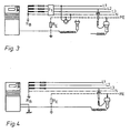
- FIG. 3 again illustrate the possibilities that arise when connecting the measuring device to the network.
- an FI switch is checked for functionality, while according to FIG. 4 an earth resistance is measured.
- Both a measurement with the measuring plug which can be plugged directly into a socket and with the contact adapter placed on the measuring plug are possible.
- the contact adapter advantageously allows two-pole measurement. Both measurements can be carried out with or without an earth probe. If an earth probe is used, as shown in FIG. 4, it is not the voltage drop but the principle of current / voltage measurement that is used.
Landscapes
- Physics & Mathematics (AREA)
- General Physics & Mathematics (AREA)
- Measurement Of Resistance Or Impedance (AREA)
- Testing Electric Properties And Detecting Electric Faults (AREA)
- Testing Relating To Insulation (AREA)
- Gas-Insulated Switchgears (AREA)
- Protection Of Generators And Motors (AREA)
- Control Of Motors That Do Not Use Commutators (AREA)
Priority Applications (1)
| Application Number | Priority Date | Filing Date | Title |
|---|---|---|---|
| AT85106334T ATE63170T1 (de) | 1984-06-13 | 1985-05-23 | Messgeraet zur ueberpruefung der schutzmassnahmen in elektrischen anlagen. |
Applications Claiming Priority (2)
| Application Number | Priority Date | Filing Date | Title |
|---|---|---|---|
| DE19843421880 DE3421880A1 (de) | 1984-06-13 | 1984-06-13 | Messgeraet zur ueberpruefung der schutzmassnahmen in elektrischen anlagen |
| DE3421880 | 1984-06-13 |
Publications (3)
| Publication Number | Publication Date |
|---|---|
| EP0166209A2 true EP0166209A2 (fr) | 1986-01-02 |
| EP0166209A3 EP0166209A3 (en) | 1988-03-23 |
| EP0166209B1 EP0166209B1 (fr) | 1991-05-02 |
Family
ID=6238230
Family Applications (1)
| Application Number | Title | Priority Date | Filing Date |
|---|---|---|---|
| EP19850106334 Expired - Lifetime EP0166209B1 (fr) | 1984-06-13 | 1985-05-23 | Appareil de contrôle des mesures de protection dans des installations électriques |
Country Status (3)
| Country | Link |
|---|---|
| EP (1) | EP0166209B1 (fr) |
| AT (1) | ATE63170T1 (fr) |
| DE (2) | DE3421880A1 (fr) |
Cited By (4)
| Publication number | Priority date | Publication date | Assignee | Title |
|---|---|---|---|---|
| EP0504514A1 (fr) * | 1991-01-31 | 1992-09-23 | John Fluke Mfg. Co., Inc. | Commutateur à multi-fonction et à multimode pour un instrument |
| EP0633475A3 (fr) * | 1993-07-06 | 1995-09-20 | Metrawatt Gmbh Gossen | Adapteur pour appareils électriques. |
| AT405768B (de) * | 1997-11-04 | 1999-11-25 | Lem Norma Gmbh | Verfahren und vorrichtung zur messung des schleifenwiderstandes in schutzschalter-geschützten netzen |
| US9719813B2 (en) | 2013-03-14 | 2017-08-01 | Scott Technologies, Inc. | Connector mechanism for safely and quickly attaching and detaching a sensor |
Family Cites Families (8)
| Publication number | Priority date | Publication date | Assignee | Title |
|---|---|---|---|---|
| DE2607606C2 (de) * | 1976-02-25 | 1978-03-23 | Mueller, Wolfgang, 6368 Bad Vilbel | Potentialprüfer |
| DE2633786C2 (de) * | 1976-07-28 | 1982-12-23 | Metrawatt GmbH, 8500 Nürnberg | Schaltungsanordnung zur Überprüfung von Schutzkontakt-Steckdosen |
| DE2855165A1 (de) * | 1978-12-20 | 1980-07-10 | Lauerer Friedrich | Elektrisches messgeraet |
| GB2049189B (en) * | 1979-03-16 | 1983-12-21 | Sharp Kk | Measuring instrument with audible output |
| DE2914761C2 (de) * | 1979-04-11 | 1980-11-06 | Siemens Ag, 1000 Berlin Und 8000 Muenchen | Gerät zum Messen von Gleich- oder Wechselspannungen sowie der Werte von elektrischen Widerständen |
| US4314312A (en) * | 1980-04-14 | 1982-02-02 | Amp Incorporated | Programming means |
| DE3130786A1 (de) * | 1981-08-04 | 1983-02-24 | Phywe AG, 3400 Göttingen | Umschaltbares messgeraet fuer gleich- und/oder wechselstroeme sowie gleich- und/oder wechselspannungen |
| DE3151261A1 (de) * | 1981-12-24 | 1983-07-07 | Alois Zettler Elektrotechnische Fabrik GmbH, 8000 München | Pruefgeraet zur pruefung von 2-poligen schutzkontaktsteckdosen in verbraucheranlagen mit fehlerstromschutzschaltung |
-
1984
- 1984-06-13 DE DE19843421880 patent/DE3421880A1/de not_active Withdrawn
-
1985
- 1985-05-23 DE DE8585106334T patent/DE3582700D1/de not_active Expired - Lifetime
- 1985-05-23 EP EP19850106334 patent/EP0166209B1/fr not_active Expired - Lifetime
- 1985-05-23 AT AT85106334T patent/ATE63170T1/de not_active IP Right Cessation
Cited By (5)
| Publication number | Priority date | Publication date | Assignee | Title |
|---|---|---|---|---|
| EP0504514A1 (fr) * | 1991-01-31 | 1992-09-23 | John Fluke Mfg. Co., Inc. | Commutateur à multi-fonction et à multimode pour un instrument |
| EP0633475A3 (fr) * | 1993-07-06 | 1995-09-20 | Metrawatt Gmbh Gossen | Adapteur pour appareils électriques. |
| AT405768B (de) * | 1997-11-04 | 1999-11-25 | Lem Norma Gmbh | Verfahren und vorrichtung zur messung des schleifenwiderstandes in schutzschalter-geschützten netzen |
| US9719813B2 (en) | 2013-03-14 | 2017-08-01 | Scott Technologies, Inc. | Connector mechanism for safely and quickly attaching and detaching a sensor |
| US10024698B2 (en) | 2013-03-14 | 2018-07-17 | Scott Technologies, Inc. | Connector mechanism for a sensor |
Also Published As
| Publication number | Publication date |
|---|---|
| DE3582700D1 (de) | 1991-06-06 |
| ATE63170T1 (de) | 1991-05-15 |
| EP0166209A3 (en) | 1988-03-23 |
| EP0166209B1 (fr) | 1991-05-02 |
| DE3421880A1 (de) | 1985-12-19 |
Similar Documents
| Publication | Publication Date | Title |
|---|---|---|
| DE3151261C2 (fr) | ||
| DE102022112463B4 (de) | Vorrichtung und Anordnung zum Überprüfen der Funktionsfähigkeit einer Ladestation | |
| EP0166209B1 (fr) | Appareil de contrôle des mesures de protection dans des installations électriques | |
| DE3421829C2 (fr) | ||
| DE1137115B (de) | Schaltungsanordnung zur Pruefung von Fehlerstrom- und Fehlerspannungsschutzschaltern | |
| DE4002603A1 (de) | Spannungspruefer | |
| EP0006602B1 (fr) | Procédé et circuit pour contrôler des disjoncteurs de protection contre les défauts de courant et de tension | |
| DE3726708C2 (de) | Anordnung zur Prüfung der Funktion einer Meß- oder Kontrollvorrichtung | |
| DE2653704B1 (de) | Verfahren zum Pruefen von Fl- und FU-Schutzschaltungen und Anordnung zur Durchfuehrung dieses Verfahrens | |
| DE2755983C3 (de) | Gerat zur Prüfung des Erdungswiderstandes in mit Fehlerstromschutzschaltern ausgestatteten Netzen | |
| DE1943714C3 (de) | Tragbares Schutzschaltungs-Prüfgerät | |
| DE2652190C3 (de) | Schaltungsanordnung mit einer Sicherheitssteckdosenleiste zum Feststellen der Qualität des Schutzleiters | |
| DE102007019750A1 (de) | Schutzschalter und Prüfeinrichtung für einen Schutzschalter, insbesondere für einen Niederspannungsleistungsschalter | |
| DE29815829U1 (de) | Vorrichtung zur handbetätigten Messung elektrischer Signale | |
| DE887676C (de) | Kabeladern-Auspruefungsgeraet | |
| DE3213749A1 (de) | Schaltungsanordnung zur erniedrigung des eingangswiderstandes einer zweipoligen hochohmigen pruefeinrichtung | |
| DE19846163A1 (de) | Isolationsprüfvorrichtung | |
| DE1805584B2 (de) | Geraet zur kontrolle von eingebauten elektrizitaetszaehlern | |
| DE2738148C2 (de) | Einrichtung zur elektrischen Selbstprüfung und/oder zur Funktionsoder Schadensprüfung von in Prüflingen angeordneten Verdrahtungen | |
| DE1248795B (de) | Prufhandgerat fur die elektrische Installationstechnik | |
| DE1588924A1 (de) | Pruefeinrichtung fuer elektronische Schutz- und Steuerungsglieder | |
| DE1056263B (de) | Geraet zur Pruefung der richtigen Beschaltung und der Unversehrtheit der Stromzufuehrungen von unter Spannung stehenden Schutzkontaktsteckdosen | |
| DE29719119U1 (de) | Spannungsprüfgerät | |
| DE2526365A1 (de) | Pruefgeraet mit pruefschaltung zur spannungsfeststellung sowie zur anzeige der phasenfolge in drehstrom-netzen | |
| DE2009170B2 (de) | Spannungspruefer |
Legal Events
| Date | Code | Title | Description |
|---|---|---|---|
| PUAI | Public reference made under article 153(3) epc to a published international application that has entered the european phase |
Free format text: ORIGINAL CODE: 0009012 |
|
| AK | Designated contracting states |
Designated state(s): AT BE DE FR IT NL SE |
|
| PUAL | Search report despatched |
Free format text: ORIGINAL CODE: 0009013 |
|
| AK | Designated contracting states |
Kind code of ref document: A3 Designated state(s): AT BE DE FR IT NL SE |
|
| 17P | Request for examination filed |
Effective date: 19880701 |
|
| RAP1 | Party data changed (applicant data changed or rights of an application transferred) |
Owner name: ASEA BROWN BOVERI AKTIENGESELLSCHAFT |
|
| 17Q | First examination report despatched |
Effective date: 19900724 |
|
| GRAA | (expected) grant |
Free format text: ORIGINAL CODE: 0009210 |
|
| AK | Designated contracting states |
Kind code of ref document: B1 Designated state(s): AT BE DE FR IT NL SE |
|
| REF | Corresponds to: |
Ref document number: 63170 Country of ref document: AT Date of ref document: 19910515 Kind code of ref document: T |
|
| ET | Fr: translation filed | ||
| ITF | It: translation for a ep patent filed | ||
| REF | Corresponds to: |
Ref document number: 3582700 Country of ref document: DE Date of ref document: 19910606 |
|
| PLBE | No opposition filed within time limit |
Free format text: ORIGINAL CODE: 0009261 |
|
| STAA | Information on the status of an ep patent application or granted ep patent |
Free format text: STATUS: NO OPPOSITION FILED WITHIN TIME LIMIT |
|
| RIN2 | Information on inventor provided after grant (corrected) |
Free format text: ZIEGLER, HERBERT * HOCHREUTHER, KARL * KINDERMANN ROBERT |
|
| 26N | No opposition filed | ||
| EAL | Se: european patent in force in sweden |
Ref document number: 85106334.7 |
|
| PGFP | Annual fee paid to national office [announced via postgrant information from national office to epo] |
Ref country code: FR Payment date: 19960515 Year of fee payment: 12 |
|
| PGFP | Annual fee paid to national office [announced via postgrant information from national office to epo] |
Ref country code: SE Payment date: 19960521 Year of fee payment: 12 Ref country code: BE Payment date: 19960521 Year of fee payment: 12 |
|
| PGFP | Annual fee paid to national office [announced via postgrant information from national office to epo] |
Ref country code: AT Payment date: 19960522 Year of fee payment: 12 |
|
| PGFP | Annual fee paid to national office [announced via postgrant information from national office to epo] |
Ref country code: NL Payment date: 19960529 Year of fee payment: 12 |
|
| PG25 | Lapsed in a contracting state [announced via postgrant information from national office to epo] |
Ref country code: AT Effective date: 19970523 |
|
| PG25 | Lapsed in a contracting state [announced via postgrant information from national office to epo] |
Ref country code: SE Effective date: 19970524 |
|
| PG25 | Lapsed in a contracting state [announced via postgrant information from national office to epo] |
Ref country code: BE Effective date: 19970531 |
|
| BERE | Be: lapsed |
Owner name: ASEA BROWN BOVERI A.G. Effective date: 19970531 |
|
| PG25 | Lapsed in a contracting state [announced via postgrant information from national office to epo] |
Ref country code: NL Effective date: 19971201 |
|
| PG25 | Lapsed in a contracting state [announced via postgrant information from national office to epo] |
Ref country code: FR Free format text: LAPSE BECAUSE OF NON-PAYMENT OF DUE FEES Effective date: 19980130 |
|
| EUG | Se: european patent has lapsed |
Ref document number: 85106334.7 |
|
| NLV4 | Nl: lapsed or anulled due to non-payment of the annual fee |
Effective date: 19971201 |
|
| REG | Reference to a national code |
Ref country code: FR Ref legal event code: ST |
|
| PGFP | Annual fee paid to national office [announced via postgrant information from national office to epo] |
Ref country code: DE Payment date: 19980528 Year of fee payment: 14 |
|
| PG25 | Lapsed in a contracting state [announced via postgrant information from national office to epo] |
Ref country code: DE Free format text: LAPSE BECAUSE OF NON-PAYMENT OF DUE FEES Effective date: 20000301 |