EP0166213B1 - Ski boot incorporating a flex control device - Google Patents
Ski boot incorporating a flex control device Download PDFInfo
- Publication number
- EP0166213B1 EP0166213B1 EP85106353A EP85106353A EP0166213B1 EP 0166213 B1 EP0166213 B1 EP 0166213B1 EP 85106353 A EP85106353 A EP 85106353A EP 85106353 A EP85106353 A EP 85106353A EP 0166213 B1 EP0166213 B1 EP 0166213B1
- Authority
- EP
- European Patent Office
- Prior art keywords
- shell
- interference element
- ski boot
- control device
- quarter
- Prior art date
- Legal status (The legal status is an assumption and is not a legal conclusion. Google has not performed a legal analysis and makes no representation as to the accuracy of the status listed.)
- Expired
Links
- 238000006073 displacement reaction Methods 0.000 claims abstract description 4
- 239000007787 solid Substances 0.000 claims 1
- 230000003247 decreasing effect Effects 0.000 description 3
- 230000010355 oscillation Effects 0.000 description 3
- 230000000694 effects Effects 0.000 description 2
- 230000004075 alteration Effects 0.000 description 1
- 230000008859 change Effects 0.000 description 1
- 238000010276 construction Methods 0.000 description 1
- 238000003780 insertion Methods 0.000 description 1
- 230000037431 insertion Effects 0.000 description 1
- 230000002452 interceptive effect Effects 0.000 description 1
- 238000012986 modification Methods 0.000 description 1
- 230000004048 modification Effects 0.000 description 1
- 230000003534 oscillatory effect Effects 0.000 description 1
- 230000035515 penetration Effects 0.000 description 1
Images


Classifications
-
- A—HUMAN NECESSITIES
- A43—FOOTWEAR
- A43B—CHARACTERISTIC FEATURES OF FOOTWEAR; PARTS OF FOOTWEAR
- A43B5/00—Footwear for sporting purposes
- A43B5/04—Ski or like boots
- A43B5/0427—Ski or like boots characterised by type or construction details
- A43B5/0452—Adjustment of the forward inclination of the boot leg
- A43B5/0454—Adjustment of the forward inclination of the boot leg including flex control; Dampening means
- A43B5/0458—Adjustment of the forward inclination of the boot leg including flex control; Dampening means with the actuator being disposed at the front side of the boot
Definitions
- This invention relates to a ski boot incorporating a flex control device.
- a currently encountered problem in the making of ski boots is that of enabling the user to adjust the boots' flexibility as desired, flex being viewed herein as the resistance offered to the forward flexing of the quarter relatively to the boot shell, that is to the rotation of the quarter about a substantially horizontal transverse axis to the foot main direction.
- the flex control devices currently in use are generally based on the use of variously calibrated elastic means which provide a force, adjustable at will, opposing the oscillation of the quarter with respect to the shell see for example FR-A-2 256 734.
- a further object of this invention is to provide a ski boot as indicated, wherein flexibility can be adjusted without the use of elastic means which, in addition to being complicated to install, as mentioned, incur serious calibration problems.
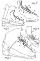
- a ski boot incorporating a flex control device which ski boot would advantageously be of the rear entrance type, comprises a shell 1 whereto a front quarter 2 and a rear quarter 3 are pivotally connected.
- the quarters 2 and 3 can, as usual, oscillate about a substantially horizontal axis, transverse to the longitudinal direction of the user's foot.
- an interference element may be positioned in a variable fashion which, by interacting between the shell and quarter at the overlap area of the quarter on the shell, produces a greater or lesser bias force as dictated by the positioning of the interference element, thereby increasing or decreasing the amount of flex, i.e. the force which should be applied to oscillate the front quarter about ssaid horizontal axis.
- the inteference element comprises a wedge-like body, indicated at 10, which is supported on the shell 1 and has its tapering end oriented to face the front quarter.
- the wedge-like element 10 is connected rigidly to a slider 11 movable along a longitudinal rib 12 provided on the front upper portion of the shell 1.
- the slider 11 defines at the top a fin 13, advantageously formed integral with the slider, which has a grip lug 14 and engagement dog 15 adapted for removable insertion into any of the notches 17 formed in the longitudinal rib 12.
- the wedge 10 will fit more or less deeply below the front edge of the front quarter 2, thus providing a greater or lesser bias force opposing the oscillatory movement of the front quarter 2 in a forward direction with respect to the shell.
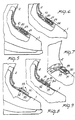
- the wedge-like body 10 is connected to a rod 20 associated rigidly with a threaded pawl 21 rotatively engaging with the interior of a threaded axial seat 22 in a cylindrical body 23 wihch is advantageously knurled on the outside and supported rotatably on the shell 1.
- the means of varying the positioning of the wedge 10 comprise a serrated slider 30 formed with a longitudinal throughgoing slot 31 which is engaged by a rod 32 having a small lever 13 journalled thereto which has a cam portion 34 acting by contact on the outer surface of the serrated slider 31, to clamp it against a fixed serration 35 provided on the shell 1.
- the means of varying the positioning of the wedge 10 comprise here a rod 40 having two oppositely handed thread sections 40a and 40b and being rotatably supported on the shell 1 in a transverse direction to the longitudinal direction of the shell.
- a grip lug 41 On one end of the rod 40, outside of the shell 1, there is provided a grip lug 41 which allows the rod 40 to be rotated.
- barrels 42 having a diametrical threaded hole and performing, as the rod 40 is rotated, a translatory movement in opposite directions along the rod.
- Articulated to the barrels 42 are the ends of a pair of connecting rods 43 which are articulated with their other ends to a lug 44 connected, inside the shell 1, to the forward end of the wedge 10 which, like in the previous embodiments, is accommodated between the front quarter 2 and the shell.
- the barrels 42 are moved linearly and consequently, through the kinematic linkage formed by the connecting rods, the wedge. 10 is moved to a greater or lesser depth bleow the front quarter 2, which results in a variation of the bias conditions.
- a further embodiment of the means of varying the positioning of the interference element formed of the wedge 10 is shown therein, which comprises a knob 50 accessible on the shell outside at an upper portion thereof and connected to a shaft 51 extending substantially perpendicularly to the shell and to which there is connected a first bevel gear 53, coaxial with the shaft 51 and meshing with a second bevel gear 54 supported against translation on a shoulder 55 defined by the shell and defining on its interior an axial threaded seat in engagement with a threaded rod 56, perpendicular to the shaft 51 and defining a throughgoing hole 57 for the shaft to extend through.
- a knob 50 accessible on the shell outside at an upper portion thereof and connected to a shaft 51 extending substantially perpendicularly to the shell and to which there is connected a first bevel gear 53, coaxial with the shaft 51 and meshing with a second bevel gear 54 supported against translation on a shoulder 55 defined by the shell and defining on its interior an axial threaded seat in engagement with a threaded rod 56, per
- the threaded rod 56 is connected to the wedge 10 such that on turning the knob, the preset coulping of the two bevel gears results in a translation in either direction of the threaded rod and consequently of the wedge 10 connected thereto with a more or less deep fitting thereof below the quarter 2.
- the means of varying the positioning of the wedge 10 comprises a variable length tie rod 60 having two threaded sections 61 and 62 joined together by a rotatable threaded bushing 63 which can be turned to change the working length of the tie rod.
- the tie rod 60 is journalled with one end to the middle portion of an actuating lever 65 articulated to the shell, and with the other end, the tie rod 60 is articulated to the wedge 10 which may be optionally, slidingly guided on the shell.
- the extent of the wedge 10 penetration below the quarter 2 can be adjusted at will, to again produce the bias adjustment conditions mentioned heretofore.
- FIG. 22 to 24 there is shown a further embodiment of means for varying the positioning of the wedge, which comprise an articulated body having a variable working length section 70 consisting of first and second threaded sections 71 and 72 joined by a threaded sleeve 73 rotatably arranged for adjusting the working length of the threaded element 70 which is articulated at one end to the shell, and at the other end thereof, to an intermediate body 74 articulated, in turn, to the wedge 10 which has, on its tapering end, a bent over section 75 to prevent it from slipping out of the area underlying the front quarter 2.
- a variable working length section 70 consisting of first and second threaded sections 71 and 72 joined by a threaded sleeve 73 rotatably arranged for adjusting the working length of the threaded element 70 which is articulated at one end to the shell, and at the other end thereof, to an intermediate body 74 articulated, in turn, to the wedge 10 which has, on its tapering end, a bent over section 75
- the position of the wedge can be adjusted in a similar manner to that of the preceding embodiment, but without using a lever arm.
- the pivot points are located such that the intermediate pivot point between the tie rod 70 and intermediate section 74 is positioned between the shell and a line joining the points of articulation of the intermediate section to the wedge 10 and of the tie rod to the shell, thereby any axial actions on the wedge would tend to move it toward the shell and not away from it.
- the wedge element 10 is connected to the end of a serrated strap 80 which is received slidably between arms 81 of a base 82 attached to the shell 1.
- the arms 81 support a rocking pawl 83 which is urged elastically with its serrated end against the serrated strap 80 to prevent the strap from slipping and the wedge 10 from moving in a wedge withdrawal direction.
- the pawl 83 has one end 83a operable to disengage its serrated end from the strap 80 and allow the strap to slip freely.
- the invention achieves its objects, and in particular that a ski boot is provided wherein the flex control device makes no use of elastic elements, but merely of the greater or lesser interference of an interference element, advantageously composed of a wedge-like body which is inserted between the front quarter and shell such that, according to the position of the wedge-like body it produces a greater or lesser bias force opposing the oscillation of the front quarter relatively to the shell.
- the interfering element may be obtained with any other shimming arrangements however conformed, rather than with the wedge . element, which may have an arcuated surface.
- the interference element 10 may be constituted of a hose member 10a enclosing in a tight manner an air chamber therein, and having a plate member 10b fixed on the top thereof.
- An abutment ridge 1a may be provided on the shell portion 1 so that when the hose 10a is compressed between the ridge 1a and the pushing member 80, the hose expands upwardly the plate 10a, obtaining thereby the desired wedging effect.
- any materials may be used to suit individual requirements.
Landscapes
- Health & Medical Sciences (AREA)
- General Health & Medical Sciences (AREA)
- Physical Education & Sports Medicine (AREA)
- Footwear And Its Accessory, Manufacturing Method And Apparatuses (AREA)
- Flexible Shafts (AREA)
- Diaphragms And Bellows (AREA)
Priority Applications (1)
| Application Number | Priority Date | Filing Date | Title |
|---|---|---|---|
| AT85106353T ATE46426T1 (de) | 1984-05-31 | 1985-05-23 | Skischuh mit eingebauter vorrichtung zur regelung der biegsamkeit. |
Applications Claiming Priority (2)
| Application Number | Priority Date | Filing Date | Title |
|---|---|---|---|
| IT21197/84A IT1174141B (it) | 1984-05-31 | 1984-05-31 | Scarpone da sci con dispositivo per la regolazione della flessibilita' |
| IT2119784 | 1984-05-31 |
Publications (2)
| Publication Number | Publication Date |
|---|---|
| EP0166213A1 EP0166213A1 (en) | 1986-01-02 |
| EP0166213B1 true EP0166213B1 (en) | 1989-09-20 |
Family
ID=11178231
Family Applications (1)
| Application Number | Title | Priority Date | Filing Date |
|---|---|---|---|
| EP85106353A Expired EP0166213B1 (en) | 1984-05-31 | 1985-05-23 | Ski boot incorporating a flex control device |
Country Status (5)
| Country | Link |
|---|---|
| US (1) | US4667424A (it) |
| EP (1) | EP0166213B1 (it) |
| AT (1) | ATE46426T1 (it) |
| DE (1) | DE3573060D1 (it) |
| IT (1) | IT1174141B (it) |
Families Citing this family (22)
| Publication number | Priority date | Publication date | Assignee | Title |
|---|---|---|---|---|
| IT219881Z2 (it) * | 1985-02-01 | 1993-05-19 | Nordica Spa | Scarpone da sci con regolazione dell'inclinazione |
| DE3662963D1 (en) * | 1985-06-24 | 1989-06-01 | Lange Int Sa | Ski boot |
| FR2588165B1 (fr) * | 1985-10-09 | 1987-12-04 | Articles Sport Cie Fse | Chaussure de ski perfectionnee |
| IT1186500B (it) * | 1985-12-24 | 1987-11-26 | Nordica Spa | Scarpone da sci con dispositivo di bloccaggio del piede |
| IT209388Z2 (it) * | 1986-01-13 | 1988-10-05 | Nordica Spa | Regolatore di appoggio per gambali di scarponi da sci. |
| IT209272Z2 (it) * | 1986-08-04 | 1988-09-20 | Nordica Spa | Dispositivo di regolazione della flessibilita', particolaremente per scarponi da sci. |
| IT1210432B (it) * | 1987-03-06 | 1989-09-14 | Nordica Spa | Dispositivo per la regolazione della flessibilita' in uno scarpone da sci. |
| FR2619684B1 (fr) * | 1987-09-02 | 1990-03-02 | Salomon Sa | Chaussure de ski alpin a tige articulee |
| US5026087A (en) * | 1988-07-27 | 1991-06-25 | Wulf Elmer B | Ski boot and ski boot-binding |
| US4880251A (en) * | 1988-07-27 | 1989-11-14 | Wulf Elmer B | Ski boot and safety binding |
| CH678591A5 (it) * | 1988-08-01 | 1991-10-15 | Dynafit Skischuh Gmbh | |
| CH678385A5 (it) * | 1989-01-27 | 1991-09-13 | Lange Int Sa | |
| IT1235308B (it) * | 1989-07-31 | 1992-06-26 | Nordica Spa | Dispositivo di chiusura, particolarmente per scarponi da sci. |
| FR2691332A1 (fr) * | 1992-05-25 | 1993-11-26 | Salomon Sa | Dispositif à curseur pour le contrôle de la flexion de la tige d'une chaussure de ski. |
| AT401216B (de) * | 1993-07-06 | 1996-07-25 | Tyrolia Freizeitgeraete | Skischuh |
| WO2001091862A2 (en) | 2000-05-31 | 2001-12-06 | K-2 Corporation | Ratchet-type buckle and snowboard binding |
| FR2816174B1 (fr) * | 2000-11-09 | 2003-09-05 | Salomon Sa | Protection d'une articulation |
| WO2009029907A2 (en) * | 2007-08-29 | 2009-03-05 | Revision Eyewear, Inc. | Attachment system for a helmet |
| US20110113535A1 (en) * | 2009-09-03 | 2011-05-19 | Lebel Stephane | Ballistic and Impact Protective System for Military Helmet Assembly |
| US9277785B2 (en) * | 2014-04-22 | 2016-03-08 | Michael Doyle | Boot fastening device |
| ITUB201650040U1 (it) * | 2016-02-24 | 2017-08-24 | Dal Bello Sport Srl | Calzatura sportiva, in particolare scarpone da sci o snowboard |
| IT202000026269A1 (it) * | 2020-11-04 | 2022-05-04 | Dalbello S R L A Socio Unico | Calzatura sportiva dotata di una lingua selettivamente snodabile |
Family Cites Families (14)
| Publication number | Priority date | Publication date | Assignee | Title |
|---|---|---|---|---|
| US3486247A (en) * | 1967-05-23 | 1969-12-30 | Francis L Franet | Ski boot construction |
| DE1810291A1 (de) * | 1968-11-22 | 1970-06-04 | Hans Goetz | Zunge fuer Skistiefel |
| JPS4898338U (it) * | 1972-02-29 | 1973-11-20 | ||
| CA966302A (en) * | 1974-01-09 | 1975-04-22 | Norstar Ski Corporation Ltd. | Ski boot |
| US3868783A (en) * | 1974-01-14 | 1975-03-04 | Norstar Ski Corp Ltd | Ski boot |
| US4095356A (en) * | 1976-10-15 | 1978-06-20 | Scott Usa, Inc. | Boot with pivoted upper |
| IT1100020B (it) * | 1978-11-15 | 1985-09-28 | Nordica Spa | Scarpone da sci |
| US4317297A (en) * | 1980-03-13 | 1982-03-02 | Hanson Industries Incorporated | Footwear with adjustable flexure |
| IT8061981U1 (it) * | 1980-12-15 | 1982-06-15 | Dolomite Spa | Scarponi da sci con gambetto elasticamente inclinabile |
| IT8122770U1 (it) * | 1981-01-31 | 1982-07-31 | Nordica Spa | Dispositivo di regolazione particolarmente per scarponi da sci |
| IT8162016U1 (it) * | 1981-12-24 | 1983-06-24 | Dolomite Spa | Scarpone da sci con hambetto elasticamente inclinabile in avanti |
| AT395512B (de) * | 1983-07-18 | 1993-01-25 | Koeflach Sportgeraete Gmbh | Schischuh mit einer schale und einem relativ zur schale schwenkbaren schaft |
| IT8322485U1 (it) * | 1983-07-26 | 1985-01-26 | Nordica Spa | Dispositivo per la variazione di inclinazione particolarmente in scarponi da sci ad entrata posteriore. |
| IT8323006V0 (it) * | 1983-09-19 | 1983-09-19 | Nordica Spa | Dispositivo per la regolazione della flessibilita' particolarmente per scarponi da sci ad entrata posteriore. |
-
1984
- 1984-05-31 IT IT21197/84A patent/IT1174141B/it active
-
1985
- 1985-05-23 US US06/737,139 patent/US4667424A/en not_active Expired - Fee Related
- 1985-05-23 AT AT85106353T patent/ATE46426T1/de not_active IP Right Cessation
- 1985-05-23 EP EP85106353A patent/EP0166213B1/en not_active Expired
- 1985-05-23 DE DE8585106353T patent/DE3573060D1/de not_active Expired
Also Published As
| Publication number | Publication date |
|---|---|
| IT8421197A0 (it) | 1984-05-31 |
| DE3573060D1 (en) | 1989-10-26 |
| ATE46426T1 (de) | 1989-10-15 |
| EP0166213A1 (en) | 1986-01-02 |
| IT8421197A1 (it) | 1985-12-01 |
| IT1174141B (it) | 1987-07-01 |
| US4667424A (en) | 1987-05-26 |
Similar Documents
| Publication | Publication Date | Title |
|---|---|---|
| EP0166213B1 (en) | Ski boot incorporating a flex control device | |
| EP0071055B1 (en) | Shoe, in particular a ski shoe, incorporating a flex and side and forward lean adjustement device | |
| US4694592A (en) | Closure device particularly for rear entrance ski boots | |
| US5918897A (en) | Snowboard binding | |
| CA1113134A (en) | Buckle and strap and method for the manufacture thereof, especially hand strap and buckle for a ski stick | |
| US4670999A (en) | Foot securing device, particularly for ski boots | |
| US4761899A (en) | Ski boot | |
| US4882857A (en) | Closure and adjustment device, particularly for ski boots | |
| US4669201A (en) | Ski boot | |
| EP0119566B1 (en) | Ski boot having an opening quarter formed of more interconnected parts | |
| US4660303A (en) | Rear-access ski boot | |
| JPH01198501A (ja) | 胴部のヒンジ連結軸の傾斜調節装置を含む靴 | |
| US5381613A (en) | Ski boot | |
| US4922633A (en) | Ski boot, particularly of the rear-entry type, with securing and adjustment device | |
| US4949480A (en) | Ski boot | |
| JPS5918044B2 (ja) | スキ−靴の前方傾斜調整装置 | |
| US5060403A (en) | Adjustable closure device particularly for ski boots | |
| EP0259721B1 (en) | Ski boot | |
| KR20060109835A (ko) | 스키 부츠 | |
| EP0284978B1 (en) | Closure and securing device, particularly for ski boots | |
| JPH02277403A (ja) | スキー靴 | |
| JPH04244101A (ja) | 胴部にヒンジ連結した硬直化用部材を有するリヤエントリー式アルペンスキー靴 | |
| US5046269A (en) | Device for adjusting the flexibility in a ski boot | |
| US4700496A (en) | Boot, in particular ski boot, with a monolithic structure | |
| JPH04226602A (ja) | 調整可能な後部サポートプレートを備えたスキーブーツ |
Legal Events
| Date | Code | Title | Description |
|---|---|---|---|
| PUAI | Public reference made under article 153(3) epc to a published international application that has entered the european phase |
Free format text: ORIGINAL CODE: 0009012 |
|
| AK | Designated contracting states |
Designated state(s): AT CH DE FR IT LI |
|
| 17P | Request for examination filed |
Effective date: 19860623 |
|
| 17Q | First examination report despatched |
Effective date: 19880226 |
|
| GRAA | (expected) grant |
Free format text: ORIGINAL CODE: 0009210 |
|
| AK | Designated contracting states |
Kind code of ref document: B1 Designated state(s): AT CH DE FR IT LI |
|
| REF | Corresponds to: |
Ref document number: 46426 Country of ref document: AT Date of ref document: 19891015 Kind code of ref document: T |
|
| REF | Corresponds to: |
Ref document number: 3573060 Country of ref document: DE Date of ref document: 19891026 |
|
| REG | Reference to a national code |
Ref country code: CH Ref legal event code: PFA Free format text: NORDICA S.R.L. |
|
| ET | Fr: translation filed | ||
| ITF | It: translation for a ep patent filed | ||
| REG | Reference to a national code |
Ref country code: CH Ref legal event code: PFA Free format text: NORDICA S.P.A. |
|
| PLBE | No opposition filed within time limit |
Free format text: ORIGINAL CODE: 0009261 |
|
| STAA | Information on the status of an ep patent application or granted ep patent |
Free format text: STATUS: NO OPPOSITION FILED WITHIN TIME LIMIT |
|
| 26N | No opposition filed | ||
| REG | Reference to a national code |
Ref country code: FR Ref legal event code: TP Ref country code: FR Ref legal event code: CN Ref country code: FR Ref legal event code: CD |
|
| ITTA | It: last paid annual fee | ||
| PGFP | Annual fee paid to national office [announced via postgrant information from national office to epo] |
Ref country code: FR Payment date: 19920518 Year of fee payment: 8 |
|
| PGFP | Annual fee paid to national office [announced via postgrant information from national office to epo] |
Ref country code: CH Payment date: 19920525 Year of fee payment: 8 |
|
| PGFP | Annual fee paid to national office [announced via postgrant information from national office to epo] |
Ref country code: AT Payment date: 19920527 Year of fee payment: 8 |
|
| PGFP | Annual fee paid to national office [announced via postgrant information from national office to epo] |
Ref country code: DE Payment date: 19920721 Year of fee payment: 8 |
|
| PG25 | Lapsed in a contracting state [announced via postgrant information from national office to epo] |
Ref country code: AT Effective date: 19930523 |
|
| PG25 | Lapsed in a contracting state [announced via postgrant information from national office to epo] |
Ref country code: LI Effective date: 19930531 Ref country code: CH Effective date: 19930531 |
|
| PG25 | Lapsed in a contracting state [announced via postgrant information from national office to epo] |
Ref country code: FR Effective date: 19940131 |
|
| REG | Reference to a national code |
Ref country code: CH Ref legal event code: PL |
|
| PG25 | Lapsed in a contracting state [announced via postgrant information from national office to epo] |
Ref country code: DE Effective date: 19940201 |
|
| REG | Reference to a national code |
Ref country code: FR Ref legal event code: ST |