EP0166234A2 - Boîte de jonction pour installation de distribution d'eau - Google Patents
Boîte de jonction pour installation de distribution d'eau Download PDFInfo
- Publication number
- EP0166234A2 EP0166234A2 EP85106447A EP85106447A EP0166234A2 EP 0166234 A2 EP0166234 A2 EP 0166234A2 EP 85106447 A EP85106447 A EP 85106447A EP 85106447 A EP85106447 A EP 85106447A EP 0166234 A2 EP0166234 A2 EP 0166234A2
- Authority
- EP
- European Patent Office
- Prior art keywords
- angle
- socket
- flange
- connection
- box
- Prior art date
- Legal status (The legal status is an assumption and is not a legal conclusion. Google has not performed a legal analysis and makes no representation as to the accuracy of the status listed.)
- Granted
Links
Images



Classifications
-
- E—FIXED CONSTRUCTIONS
- E03—WATER SUPPLY; SEWERAGE
- E03C—DOMESTIC PLUMBING INSTALLATIONS FOR FRESH WATER OR WASTE WATER; SINKS
- E03C1/00—Domestic plumbing installations for fresh water or waste water; Sinks
- E03C1/02—Plumbing installations for fresh water
- E03C1/021—Devices for positioning or connecting of water supply lines
Definitions
- the invention relates to a junction box for industrial water installations according to the preamble of claim 1.
- plastic pipes are increasingly used instead of metal pipes for service water installations.
- the plastic pipes are laid in protective or insulating pipes.
- taps wash basins, cisterns, etc.
- So-called socket angles are attached by means of commercially available clamping ring screw connections, which in turn are immovably fixed in junction boxes made of plastic.
- junction boxes In the socket angle there is a connection thread into which the sanitary fittings such as surface-mounted valves (corner valves, batteries) are screwed.
- the junction boxes are anchored in the masonry (plastered) or fastened to plates (plasterboard, wood).
- the protective or insulating pipes connect directly to the junction boxes.
- the old pipe can be pulled out of the junction box and the protective pipe.
- the new tube is then reinserted from the can.
- Sufficiently large installation radii are a requirement, since the plastic pipes are very stiff and not very flexible.
- a junction box for industrial water installations is known, for example, from German utility model 77 05 225.6 and from European patent application 85 329.
- a disadvantage of the known junction boxes is that they are only designed for one area of use and for different areas of use
- the socket angle is fastened in the socket body, for example with two screws or with a union nut or with a large threaded plug made of plastic. As a result, the assembly of the can angle is time-consuming.
- the invention has for its object to provide a junction box for domestic water installations, which is suitable for all applications.
- the junction box to be created should also be easy to assemble, with a tight fit of the box angle in the box body being ensured.
- the junction box according to the invention has one and the same box body and one and the same box angle for all applications - flush mounting, arrangement for pre-wall installation, attachment to lightweight or wooden panel walls or attachment to a concealed cistern.
- the socket body has fastening flanges on both its front and rear sides with through-openings and / or threaded openings for the passage or screwing in of fastening screws / bolts.
- the can body is attached over the front or over the rear fastening flange, whereby fastening screws are passed through the through openings or screwed into the threaded openings.
- the can angle In the assembled position, the can angle is firmly attached to all sides of the can angle due to the interacting contact surfaces and in the can body. It only has to be locked from the insertion side, for which purpose an elastically yielding catch can be formed on the can body, for example, which projects in front of a nose of the can angle in the assembled or installed position of the can angle.
- Other catches are also conceivable, for example steel springs or rings fastened in the box. Fastening with a screw is also possible, whereby one screw is sufficient since the socket angle is firmly attached on all sides.
- connection thread on the socket angle in front of the plane of the front fastening flange and by eccentric arrangement of the socket angle connection thread result in a flat construction of the connection box and favorable assembly and disassembly conditions by preventing the plastic tube from being bent excessively.
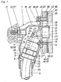
- Fig. 1 shows the junction box 1 in longitudinal section with the socket body 2 and the socket angle 3 used.
- the socket angle 3 has a (generally known) clamping ring screw connection 4 for connecting a flexible plastic pipe for service water.
- the clamping ring connection is located inside the screw connection 4 as far as possible from the screw end 6, so that the hose end 7 projects far into the screw connection.
- the plastic tube 5 is not curved so much because its end 7 is already close to the insertion opening of the can body 2.
- a lower cylinder jacket surface 8 of the screw connection 4 is enclosed on all sides by a cylinder jacket in the installation position of the can angle shown Surface 9 on the can body 2. There is play of approx. 0.2 mm between the two surfaces.
- An upper cylinder jacket surface 10 of the screw connection 4 lies against the jacket surface 11 ′′ of a partial cylinder of the can body 2. All cylinder jacket surfaces have a common axis 11.
- the axis 11 is at an obtuse angle to axes 12 and 13, which run parallel to one another (see also FIG. 7 and 8.
- the axis 13 is the center of a cylinder flange 33 at the can angle 3.
- the cylindrical surface 14 of the flange 33 lies up to the middle 16-17 (FIGS.
- Axis 12 is the central axis of the connecting thread 21 of the can angle 3.
- the nozzle or corner valve (not shown) is egg screwed. The water thus flows through the plastic tube 5 and bores 22 and 23 within the can angle into the valve.
- the compression fitting 4 has a dual function by: serves on the one hand for connecting the plastic tube 5 and on the other hand with its outer cylindrical surfaces as a centering and supporting element.
- the can angle 3 is held by a locking lever 24 (FIGS. 1, 7 and 8).
- the lower end of the locking lever 24 is firmly connected to the side wall 25 of the can body 2 up to a bending point 26 (see also FIG. 2).
- the catch 28 lies in the installation position of the can angle 3 shown in FIG. 1 with its surface 29 over the surface 30 of a nose 31 of the can angle 3, so that the can angle is secured against being pulled out upwards.
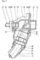
- Another fuse is shown in FIG. 3.
- a screw 32 (see also FIGS. 7 and 8), the head of which is seated in or on the flange 33 of the can bracket 3, is screwed into a nut 34 which is firmly cast into the can body 2.
- a single screw is sufficient for securing, since the socket angle 3 is otherwise held in a positive manner in all directions.
- the locking lever can then be omitted.
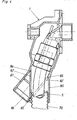
- Fig. 2 shows the can angle 3 with connected plastic tube 5 in a partially installed or removed state.
- the can angle 3 is pushed further into the can body 2 until the central axis 11 'of the can angle 3 coincides with the axis 11 (FIG. 1) and the upper vertex 35 of the end face 18 of the flange 33 at a slope 36 of the insertion opening of the can body 2 is present.
- the screw end 6 is then in front of the cylindrical surface 9 of the can body 2.
- By moving the can angle 3 in the direction of the axis 11 downwards it is brought into its final position.
- the apex 35 of the end face 18 of the cylinder flange 33 slides along the bevel 36 of the insertion opening of the can body 2.
- the bevel 36 is delimited by the inner semicircular arch 37 at the transition to the collar 20 and through the outer oval 38, which begins in the middle 16-17 (Figs. 7 and 8).
- the bevel 36 runs parallel to the axis 11.
- the locking lever 24 is pushed back by the clamping ring screw connection 4 during the introduction of the can angle 3 (FIG. 2), ie it deforms elastically. Did he. Can angle 3 reaches its final position, the locking lever 24 springs back and the locking 28 comes to rest over the nose 31 of the can angle 3 and locks it against being pulled out.
- the locking is released by pushing the locking lever 24 back with a screwdriver or the like.
- an opening 27 (FIGS. 2, 7 and 8) is provided in the front wall of the can body 2, through which the screwdriver can be inserted.
- the can angle 3 is then pulled out in the reverse order of the insertion.
- the removal and installation process of the can angle 3 is hampered by the round opening 39 in the wall structure (masonry, lightweight wall). This can be clearly seen in FIG. 2.
- the opening 39 must be smaller than the decorative rosette that covers the opening 39 after the finished installation.
- the opening 39 can be given the required small diameter. If the axis 12 of the connecting thread 21 coincided with the axis 13 of the flange 33 (central arrangement), the upper boundary line of the opening 39 could also not be lowered, since the upper apex 35 of the end face 18 of the flange 33 continues would lie in the same place (Fig. 2).
- the plastic tube 5 When inserting or pulling out the can angle 3 into or out of the can body 2, the plastic tube 5 is slightly curved due to the obtuse-angled arrangement of the axis 11 to the axes 12, 13, which, since the plastic tube is thick-walled and unwilling to bend, makes handling easier means.
- This obtuse-angled arrangement of the axis 11 to the axes 12, 13 is possible - without a large installation depth of the junction box 1 being necessary - by the arrangement of the connecting thread 21 in the assembled position of the box angle 3 essentially outside the insertion opening of the box body 2.
- Box dimensions which are as flat as possible should be aimed at in order to achieve small hole dimensions for inserting the box into the masonry, which require little chiseling work.
- the described junction box 1 can be used universally for the various applications.
- a fastening flange 40, 59 (FIG. 7) or 40 ', 59' (FIG. 8) is provided for the different fastening methods on the front and rear.
- 44 ', 45', 46 '(FIG. 8) fastening screws 47, 48, 49 (FIG. 2), 50, 51, 52 (FIG. 1) and 53, 54, 55 (FIGS. 5 and 6) are carried out or screwed in.
- the attachment of the junction box 1 to a plasterboard 66 shows Fig. L. Tiles 67 and the tile adhesive 68 are also shown in section.
- the box 1 is fastened with screws 50, 51, 52, the countersunk heads of which rest on a self-contained steel ring 69 and in nuts 44, 45, 46 (FIG. 7) or 44 ', 45', 46 '(Fig. 8) are screwed, which are cast in the can bodies 2.
- junction box 1 for flush mounting is also shown in FIG. 1.
- a hole is made in the masonry, the box 1 is inserted and walled in, an attachment to the front flange 40, 40 'is omitted.
- a protective tube 70 which encloses the plastic tube 5, is also laid and plastered in the masonry.
- the screws are seated in bores 62, 63 (FIG. 7) and 62 ', 63' (FIG. 8) of the rear fastening flange 59 and 59 ', respectively.
- FIG. 2 the use of the junction box 1 is shown in a wooden panel wall construction. On average, the wall components with wood chipboard 87, plasterboard 88 and tiles 89 are indicated.
- the box 1 is fastened to the wood chipboard 87 with screws 47, 48, 49, which protrude through bores in the front fastening flange 40 or 40 '.
- FIG. 3 The arrangement of the box 1 for pre-wall installation is shown in FIG. 3.
- the box is fastened to the rear wall with a fastening bolt 73 so that its front flange 40 or 40 'approximately closes with the front wall.
- a thread 74 is provided in the rear fastening flange 59 or 59 ', the central axis 75 of which is aligned with the central axis 12 of the connecting thread 21.
- a lock nut 76 secures the can 1 against twisting.
- the protective tube 70 which surrounds the plastic tube 5, is laid in the free space between the two walls. The protective tube 70 should therefore not be directed vertically downward, as shown in FIG. 1, but at an acute angle to the rear.
- a guide part 77 in which the protective tube 70 is inserted, is rotatably mounted on a cylinder stub 78 of the junction box 1 and can be rotated from the position shown in FIG. 1, for example to the position corresponding to FIG. 3, so that the protective tube 70 and with it the plastic tube 5 takes the direction desired for pre-wall installation.
- a shoulder 79 on the cylinder neck 78 prevents the guide member 77 from sliding down.
- Figures 5 and 6 show the attachment of the junction box 1 to a concealed cistern 56.
- the box 1 is screwed by screws 53, 54, 55, which are screwed into the nuts 44, 45, 46 and 44 ', 45', 46 ' are attached to the outside of the .57 cistern wall.
- 6 shows a longitudinal section of the can 1 and the cistern wall 57.
- a FOG. 5
- the mounting flange must not be wider than twice the distance a.
- FIG. 8 Another possibility of designing narrow fastening flanges without breakable outer parts is shown in FIG. 8.
- the bores 41 ', 42' and 62 ', 63' are open on the side. The openings do not extend to the central axis of the bores, so that the screws are held against slipping out sideways.
- Local recesses 64, 65 are additionally provided in the side walls 25, 25 'of the can body for the screw heads.
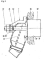
- an opening 90 (FIG. 9) corresponding to the opening 39 in FIG. 2, which will later be covered with the decorative rosette, must be left in the masonry.
- the plastering is started a plastic plug 91 inserted into the can of the can.
- the cylindrical part 92 of the plug 91 has the diameter of the desired opening in the masonry.
- the plug 91 is screwed with a threaded connector 93 into the central thread 74, in the other end of which the fastening bolt 73 (see also FIG. 3) is used, which is used for pre-wall installation.
- the thread 74 of the rear fastening flange 59 or 59 'thus fulfills two functions. After the mortar 94 has set, the plug 91 is unscrewed.
- the thread 74 can be closed with a plug 95 (FIG. 2) in order to prevent the ingress of dirt.
Landscapes
- Health & Medical Sciences (AREA)
- Life Sciences & Earth Sciences (AREA)
- Engineering & Computer Science (AREA)
- Hydrology & Water Resources (AREA)
- Public Health (AREA)
- Water Supply & Treatment (AREA)
- Laying Of Electric Cables Or Lines Outside (AREA)
- Devices That Are Associated With Refrigeration Equipment (AREA)
- Connection Or Junction Boxes (AREA)
- Forms Removed On Construction Sites Or Auxiliary Members Thereof (AREA)
- Domestic Plumbing Installations (AREA)
Priority Applications (1)
| Application Number | Priority Date | Filing Date | Title |
|---|---|---|---|
| AT85106447T ATE39520T1 (de) | 1984-05-28 | 1985-05-24 | Anschlussdose fuer brauchwasser-installationen. |
Applications Claiming Priority (2)
| Application Number | Priority Date | Filing Date | Title |
|---|---|---|---|
| DE3419938 | 1984-05-28 | ||
| DE19843419938 DE3419938A1 (de) | 1984-05-28 | 1984-05-28 | Anschlussdose fuer brauchwasser-installationen |
Publications (3)
| Publication Number | Publication Date |
|---|---|
| EP0166234A2 true EP0166234A2 (fr) | 1986-01-02 |
| EP0166234A3 EP0166234A3 (en) | 1987-04-08 |
| EP0166234B1 EP0166234B1 (fr) | 1988-12-28 |
Family
ID=6237078
Family Applications (1)
| Application Number | Title | Priority Date | Filing Date |
|---|---|---|---|
| EP85106447A Expired EP0166234B1 (fr) | 1984-05-28 | 1985-05-24 | Boîte de jonction pour installation de distribution d'eau |
Country Status (3)
| Country | Link |
|---|---|
| EP (1) | EP0166234B1 (fr) |
| AT (1) | ATE39520T1 (fr) |
| DE (2) | DE3419938A1 (fr) |
Cited By (2)
| Publication number | Priority date | Publication date | Assignee | Title |
|---|---|---|---|---|
| FR2926571A1 (fr) * | 2008-01-23 | 2009-07-24 | Claude Benit | Dispositif de montage et de raccordement de conduites d'installations sanitaires prevues en arriere d'une paroi et procede correspondant |
| EP2525000A1 (fr) * | 2011-05-19 | 2012-11-21 | Somatherm | Dispositif pour la fixation, sur une paroi, d'un raccord de canalisation |
Families Citing this family (5)
| Publication number | Priority date | Publication date | Assignee | Title |
|---|---|---|---|---|
| DE3604932A1 (de) * | 1986-02-17 | 1987-08-20 | Weerth Hans Ernst | Mehrfachanschluss-armatur fuer eine anschlussdose fuer brauchwasser-installationen |
| DE3907337A1 (de) * | 1989-03-08 | 1990-09-13 | Seppelfricke Systemtechnik Gmb | Anschlussdose fuer wasserleitungsinstallationen |
| CH679319A5 (fr) * | 1989-11-10 | 1992-01-31 | Fischer Ag Georg | |
| DE29804700U1 (de) * | 1998-03-16 | 1998-06-04 | Minol Messtechnik W. Lehmann GmbH & Co, 70771 Leinfelden-Echterdingen | Montageeinrichtung für eine Unterputzarmatur bei der Sanitärinstallation |
| EP2226430B1 (fr) | 2009-03-04 | 2015-07-29 | Geberit International AG | Dispositif de raccordement pour armatures d'écoulement |
Family Cites Families (3)
| Publication number | Priority date | Publication date | Assignee | Title |
|---|---|---|---|---|
| CH648371A5 (de) * | 1982-01-29 | 1985-03-15 | Fischer Ag Georg | Anschlusseinrichtung fuer armaturen. |
| DE8212628U1 (de) * | 1982-05-03 | 1982-09-23 | TA Rokal GmbH, 4054 Nettetal | Anschlussdose fuer eine wasserleitungsanlage |
| DE8234277U1 (de) * | 1982-12-07 | 1983-09-22 | Kraus, Kreszentia, geb. Heichele, 8000 München | Bauelement zur installation von sanitaer-armaturen, insbesondere in verbindung mit flexiblen, mediumfuehrenden rohren in mauerwerk und betonwaenden |
-
1984
- 1984-05-28 DE DE19843419938 patent/DE3419938A1/de not_active Withdrawn
-
1985
- 1985-05-24 AT AT85106447T patent/ATE39520T1/de not_active IP Right Cessation
- 1985-05-24 DE DE8585106447T patent/DE3567046D1/de not_active Expired
- 1985-05-24 EP EP85106447A patent/EP0166234B1/fr not_active Expired
Cited By (5)
| Publication number | Priority date | Publication date | Assignee | Title |
|---|---|---|---|---|
| FR2926571A1 (fr) * | 2008-01-23 | 2009-07-24 | Claude Benit | Dispositif de montage et de raccordement de conduites d'installations sanitaires prevues en arriere d'une paroi et procede correspondant |
| WO2009106771A3 (fr) * | 2008-01-23 | 2009-11-26 | Claude Benit | Dispositif de montage et de raccordement de conduites d'installations sanitaires prevues en arriere d'une paroi et procede correspondant |
| US8469403B2 (en) | 2008-01-23 | 2013-06-25 | Claude Benit | Device for mounting and connecting sanitary equipment pipes provided being a wall and corresponding method |
| EP2525000A1 (fr) * | 2011-05-19 | 2012-11-21 | Somatherm | Dispositif pour la fixation, sur une paroi, d'un raccord de canalisation |
| FR2975457A1 (fr) * | 2011-05-19 | 2012-11-23 | Somatherm | Dispositif pour la fixation, sur une paroi, d'un raccord de canalisation |
Also Published As
| Publication number | Publication date |
|---|---|
| DE3567046D1 (en) | 1989-02-02 |
| EP0166234B1 (fr) | 1988-12-28 |
| DE3419938A1 (de) | 1985-12-05 |
| ATE39520T1 (de) | 1989-01-15 |
| EP0166234A3 (en) | 1987-04-08 |
Similar Documents
| Publication | Publication Date | Title |
|---|---|---|
| EP2154297B1 (fr) | Agencement de douche | |
| EP2150657A1 (fr) | Dispositif pour fixer un appareil en suspension murale | |
| EP2041374A1 (fr) | Robinetterie sanitaire à encastrer avec un corps de base | |
| DE29820782U1 (de) | Frostsichere Armatur, insbesondere Ventil für Wasserleitungen | |
| EP1006244A2 (fr) | Dispositif de fixation pour éléments sanitaires | |
| EP0166234B1 (fr) | Boîte de jonction pour installation de distribution d'eau | |
| DE102019132130A1 (de) | Gelenkanordnung zur schwenkbaren Lagerung eines Deckels, eines Sitzes oder einer Sitz-Deckel-Garnitur an einem keramischen Sanitärgegenstand | |
| EP0960983B1 (fr) | Dispositif pour le recouvrement d'un support mural | |
| DE19510414C2 (de) | Befestigungsanordnung mit einem Installationselement | |
| CH438166A (de) | In die Wand eingebauter Klosett-Spülkasten | |
| DE20115533U1 (de) | Vorrichtung zum Verteilen von Wasser | |
| AT396269B (de) | Einrichtung zur montage einer handbrause an der seite einer badewanne | |
| DE19628780A1 (de) | Anordnung zur Schnellbefestigung einer Sanitärarmatur | |
| DE29714609U1 (de) | Vorgefertigte Montagebox für den Heizungs- und Rohrleitungsbau sowie den Sanitärbereich | |
| DE4034894C2 (de) | Wandanschlußteil für Sanitärarmaturen | |
| DE4344344A1 (de) | Kamin mit mehreren, durch Verbindungsanordnungen biegesteif miteinander verbundenen Kaminelementen | |
| EP1723285B1 (fr) | Systeme de douche | |
| DE10301320A1 (de) | Abdichtvorrichtung | |
| EP2853643A1 (fr) | Corps de raccordement pour une robinetterie encastrée | |
| DE20105345U1 (de) | Montageeinheit für die Sanitär- und Heizungsinstallation | |
| EP0861946B1 (fr) | Vanne sanitaire mitigeuse | |
| DE29504966U1 (de) | Sanitärarmatur mit wenigstens einem drehbaren Armaturengriff | |
| DE29502689U1 (de) | Anbohrvorrichtung für Rohrleitungen | |
| DE8804072U1 (de) | Montagestopfen | |
| DE102022120206A1 (de) | Einbaugarnitur mit Betätigungssicherung und Betätigungssicherung |
Legal Events
| Date | Code | Title | Description |
|---|---|---|---|
| PUAI | Public reference made under article 153(3) epc to a published international application that has entered the european phase |
Free format text: ORIGINAL CODE: 0009012 |
|
| AK | Designated contracting states |
Designated state(s): AT BE CH DE FR GB IT LI LU NL SE |
|
| ITCL | It: translation for ep claims filed |
Representative=s name: FIAMMENGHI FIAMMENGHI RACHELI |
|
| TCNL | Nl: translation of patent claims filed | ||
| EL | Fr: translation of claims filed | ||
| PUAL | Search report despatched |
Free format text: ORIGINAL CODE: 0009013 |
|
| AK | Designated contracting states |
Kind code of ref document: A3 Designated state(s): AT BE CH DE FR GB IT LI LU NL SE |
|
| 17P | Request for examination filed |
Effective date: 19870929 |
|
| 17Q | First examination report despatched |
Effective date: 19880516 |
|
| GRAA | (expected) grant |
Free format text: ORIGINAL CODE: 0009210 |
|
| AK | Designated contracting states |
Kind code of ref document: B1 Designated state(s): AT BE CH DE FR GB IT LI LU NL SE |
|
| REF | Corresponds to: |
Ref document number: 39520 Country of ref document: AT Date of ref document: 19890115 Kind code of ref document: T |
|
| REF | Corresponds to: |
Ref document number: 3567046 Country of ref document: DE Date of ref document: 19890202 |
|
| ITF | It: translation for a ep patent filed | ||
| GBT | Gb: translation of ep patent filed (gb section 77(6)(a)/1977) | ||
| PG25 | Lapsed in a contracting state [announced via postgrant information from national office to epo] |
Ref country code: LU Free format text: LAPSE BECAUSE OF NON-PAYMENT OF DUE FEES Effective date: 19890531 |
|
| ET | Fr: translation filed | ||
| REG | Reference to a national code |
Ref country code: CH Ref legal event code: PUE Owner name: HERZ ARMATUREN AKTIENGESELLSCHAFT |
|
| ITPR | It: changes in ownership of a european patent |
Owner name: CESSIONE;HERZ ARMATUREN AG |
|
| NLS | Nl: assignments of ep-patents |
Owner name: HERZ ARMATUREN AKTIENGESELLSCHAFT TE WENEN, OOSTEN |
|
| PLBE | No opposition filed within time limit |
Free format text: ORIGINAL CODE: 0009261 |
|
| STAA | Information on the status of an ep patent application or granted ep patent |
Free format text: STATUS: NO OPPOSITION FILED WITHIN TIME LIMIT |
|
| REG | Reference to a national code |
Ref country code: FR Ref legal event code: TP |
|
| 26N | No opposition filed | ||
| PGFP | Annual fee paid to national office [announced via postgrant information from national office to epo] |
Ref country code: SE Payment date: 19900423 Year of fee payment: 6 |
|
| PGFP | Annual fee paid to national office [announced via postgrant information from national office to epo] |
Ref country code: LU Payment date: 19900425 Year of fee payment: 6 |
|
| PGFP | Annual fee paid to national office [announced via postgrant information from national office to epo] |
Ref country code: FR Payment date: 19900507 Year of fee payment: 6 |
|
| PGFP | Annual fee paid to national office [announced via postgrant information from national office to epo] |
Ref country code: GB Payment date: 19900511 Year of fee payment: 6 |
|
| PGFP | Annual fee paid to national office [announced via postgrant information from national office to epo] |
Ref country code: BE Payment date: 19900515 Year of fee payment: 6 |
|
| PGFP | Annual fee paid to national office [announced via postgrant information from national office to epo] |
Ref country code: CH Payment date: 19900529 Year of fee payment: 6 |
|
| PGFP | Annual fee paid to national office [announced via postgrant information from national office to epo] |
Ref country code: NL Payment date: 19900531 Year of fee payment: 6 |
|
| PG25 | Lapsed in a contracting state [announced via postgrant information from national office to epo] |
Ref country code: GB Effective date: 19910524 |
|
| PG25 | Lapsed in a contracting state [announced via postgrant information from national office to epo] |
Ref country code: SE Effective date: 19910525 |
|
| PG25 | Lapsed in a contracting state [announced via postgrant information from national office to epo] |
Ref country code: LI Effective date: 19910531 Ref country code: CH Effective date: 19910531 Ref country code: BE Effective date: 19910531 |
|
| BERE | Be: lapsed |
Owner name: HERZ ARMATUREN A.G. Effective date: 19910531 |
|
| PG25 | Lapsed in a contracting state [announced via postgrant information from national office to epo] |
Ref country code: NL Effective date: 19911201 |
|
| NLV4 | Nl: lapsed or anulled due to non-payment of the annual fee | ||
| GBPC | Gb: european patent ceased through non-payment of renewal fee | ||
| PG25 | Lapsed in a contracting state [announced via postgrant information from national office to epo] |
Ref country code: FR Effective date: 19920131 |
|
| REG | Reference to a national code |
Ref country code: CH Ref legal event code: PL |
|
| REG | Reference to a national code |
Ref country code: FR Ref legal event code: ST |
|
| ITTA | It: last paid annual fee | ||
| ITPR | It: changes in ownership of a european patent |
Owner name: CESSIONE;SEPPELFRICKE SYSTEMTECHNIK GMBH & CO. OHG |
|
| PGFP | Annual fee paid to national office [announced via postgrant information from national office to epo] |
Ref country code: AT Payment date: 19930514 Year of fee payment: 9 |
|
| PGFP | Annual fee paid to national office [announced via postgrant information from national office to epo] |
Ref country code: DE Payment date: 19940211 Year of fee payment: 10 |
|
| PG25 | Lapsed in a contracting state [announced via postgrant information from national office to epo] |
Ref country code: AT Effective date: 19940524 |
|
| EUG | Se: european patent has lapsed |
Ref document number: 85106447.7 Effective date: 19911209 |
|
| PG25 | Lapsed in a contracting state [announced via postgrant information from national office to epo] |
Ref country code: DE Effective date: 19960201 |