EP0166434B1 - Gerät zur Prüfung der Dauerhaftigkeit eines schweren Öls - Google Patents
Gerät zur Prüfung der Dauerhaftigkeit eines schweren Öls Download PDFInfo
- Publication number
- EP0166434B1 EP0166434B1 EP85107902A EP85107902A EP0166434B1 EP 0166434 B1 EP0166434 B1 EP 0166434B1 EP 85107902 A EP85107902 A EP 85107902A EP 85107902 A EP85107902 A EP 85107902A EP 0166434 B1 EP0166434 B1 EP 0166434B1
- Authority
- EP
- European Patent Office
- Prior art keywords
- heavy oil
- stability
- testing
- filter paper
- heating
- Prior art date
- Legal status (The legal status is an assumption and is not a legal conclusion. Google has not performed a legal analysis and makes no representation as to the accuracy of the status listed.)
- Expired - Lifetime
Links
Images


Classifications
-
- G—PHYSICS
- G01—MEASURING; TESTING
- G01N—INVESTIGATING OR ANALYSING MATERIALS BY DETERMINING THEIR CHEMICAL OR PHYSICAL PROPERTIES
- G01N30/00—Investigating or analysing materials by separation into components using adsorption, absorption or similar phenomena or using ion-exchange, e.g. chromatography or field flow fractionation
-
- G—PHYSICS
- G01—MEASURING; TESTING
- G01N—INVESTIGATING OR ANALYSING MATERIALS BY DETERMINING THEIR CHEMICAL OR PHYSICAL PROPERTIES
- G01N33/00—Investigating or analysing materials by specific methods not covered by groups G01N1/00 - G01N31/00
- G01N33/26—Oils; Viscous liquids; Paints; Inks
- G01N33/28—Oils, i.e. hydrocarbon liquids
- G01N33/2805—Oils, i.e. hydrocarbon liquids investigating the resistance to heat or oxidation
Definitions
- the present invention relates to an apparatus for testing the stability of heavy oil. More particularly, the present invention relates to an apparatus suitable for testing the stability of heavy oil not only in a well-equipped laboratory but also in other places, for example, on a vessel.
- an air bath tank which a temperature of the air therein is controlled at a predetermined level and a sample heating tank are arranged in one case body so as to communicate with each other, and at least one electric heating means is disposed in the bottom portion of this case body.
- a heavy oil sample placed in a sample vessel is heated at a predetermined temperature, for example, 90 to 100°C, in the sample heating tank, and this state is maintained for 15 to 20 minutes and the sample is sufficiently stirred.
- the temperature in the tank is detected by a temperature detecting element disposed in the tank, the quantity of the electric current supplied to the above-mentioned heating means is controlled by temperature controlling means so that the temperature of the air in the tank is maintained at a predetermined level, for example, 100 ⁇ 2°C.
- a predetermined level for example, 100 ⁇ 2°C.
- One drop of the heated heavy oil sample in the sample vessel is caused to fall on a filter paper supported in the air bath tank by supporting means, and the sample-dropped filter paper is dried for about one hour. The spot spread on the filter paper is observed and the stability of the heavy oil sample is evaluated. It is preferred that this evaluation be made by comparison with a reference spot.
- a thermostat switch can be used as means for detecting the air temperature in the air bath tank.
- This thermostat switch is connected in series to a circuit for supplying an electric current to the heating means to control the air temperature in the air bath tank to a predetermined level.
- the air bath tank and the sample heating tank may be substantially closed to improve the heating efficiency of the heating means.
- the novel heavy oil stability spot test proposed by us can be carried out very easily, and the apparatus of the present invention is suitable for the field test in a vessel or the like where the experimental equipment is not sufficient.
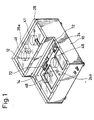
- a case body 10 comprises a sample heating tank 12 and an air bath tank 14, which are arranged in parallel in the lateral direction in the case body 10.
- the bottom face of the case body 10 is opened and a metal net member 16 is secured to the inner circumferential face of the case body 10 to cover the open face.
- the top face of a top opening 18 of the air bath tank 14 is covered with a cover 24 on the peripheral top end of the tank 14.
- the cover 24 is formed of a heat-resistant transparent plastic material.
- the top opening 18 is substantially closed by the cover 24.
- the top face of a top opening 26 of the sample heating tank 12 is covered with a cover 28 on the peripheral top end of the tank 14.
- the cover 28 is formed of a heat resistant transparent plastic material and the top opening 26 is substantially closed by the cover 28.
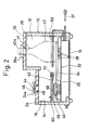
- a holding plate 32 extending in the horizontal direction in the shelf-like form is attached and secured to the inner wall of the bottom portion of the case body 19 at a position of a predetermined height.
- a heating plate 30 is placed on the top face of the hold plate 32 through an asbestos plate 34 as a heat insulating member and is horizontally held.
- the heating plate 30 comprises a plate of a metal such as iron or aluminum and an electric heater (not shown) embedded in the metal plate.
- the heating plate 30 and asbestos plate 34 are secured to the holding plate 32 by a supporting leg 36 described below.
- a power source terminal 38 of the electric heater is exposed to the space of the bottom portion of the case body 10 through the asbestos plate 34 and is connected to a power source cord 37 which is connected to the power source through the side wall of the case body 10 from said space and to a thermostat switch 50 for performing on-off control of the power source circuit 80 (Fig. 6) for the heating plate 30, as described hereinafter.
- the air bath tank 14 is constructed to have a flat space of a low height, and the sample heating tank 12 is formed in a space, the height of which is higher than that of the air bath tank 14. Both the tanks 12 and 14 are arranged to communicate with each other in their bottom portion.
- Two openings 41 are formed through the top face cover 28 of the sample heating tank 12 so that open top ends 42a of two sample vessels, for example, Erlenmeyer flasks 42, can pierce through the openings 41, respectively.
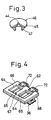
- Two sample dropping openings 48 are formed on the top face cover 24 of the air bath tank 14 so that the openings 48 can be opened or closed by a lid member 46 having a small hole 44 communicating with the outer and inner sides of the tank 14 (see Figs. 2 and 3).
- the lid member 46 comprises a disc portion 45 having the small hole 44 formed at the center and a cylindrical portion 47 contiguous to the lower face of the disc portion 45.
- the cylindrical portion 47 is fitted in the sample dropping opening 48.
- the small hole 44 is formed so as to liberate hot air present in the upper portion of the tank 14 and uniformalize.the temperature within the tank 14.
- Knobs 24a and 28a are attached to the top faces of the two covers 24 and 28, respectively.
- a filter paper holding member 62 is secured and held onto the inner wall of the case body 10 to hold a filter paper 60 horizontally at a position about 5 mm above the heating surface of the heating plate 30.
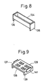
- the filter paper holding member 62 has a structure in which the filter paper 60 is inserted and gripped between an upper plate 66 and a lower plate 68, each having two each of rectangular openings 64 and 65 for exposing the sample-dropped portion of the filter paper to the position corresponding to the sample dropping opening 48.
- One side of the upper plate 66 is connected to one side of the lower plate 68 through hinges 72 arranged at two points so that they can be optionally opened and closed.
- the opening 64 of the upper plate 66 is formed to have a square shape and the opening 65 of the lower plate 68 is formed to have an oblong shape having the longer side equal to a side of the opening 64. Accordingly, the filter paper 60 held between the upper plate 66 and lower plate 68 is exposed in the square shape, and the portion of the filter paper placed on the top face of a part of the lower plate 68 projecting to the opening 64 of the side of the upper plate 66 is used as an area for recording data of the spot test described hereinafter, and the above-mentioned partial face acts as an underlying cardboard for recording the test data on the filter paper.
- a knob 67 is attached to the upper plate 66 and the above-mentioned opening and closing are performed by picking up the knob 67 between a pair of tweezers or the like.
- the supporting leg 36 is attached and secured to each of both the ends of the lower plate 68 with respect to the longitudinal direction.
- the supporting leg 36 comprises a substantially Z-shaped plate member 36 bent at a right angle at two positions, a plate member 36b secured to the inner face of the vertical part of the plate member 36a in a manner extending in parallel to the horizontal part of the plate member 36a and a plate member 36c secured to the center of the top end face of the plate member 36a in a manner extending outward in parallel to the horizontal part of the plate member 36a.
- the supporting leg 36 is attached and secured to the asbestos plate 34 and holding plate 32 by screwing a screw 40 engaged with a groove 39 formed on the outer end edge of the lower horizontal part of the substantially Z-shaped plate member 36a into the portion of the asbestos plate 34 extending around the heating plate 30 and the holding plate 32, whereby the asbestos plate 34 and holding plate 32 are secured and fixed.
- Both the end portions of the lower plate 68 with respect to the longitudinal direction are attached and secured to the plate member 36c of the supporting leg 36, whereby the filter paper holding member 62 is fixed and held in the air bath tank 14.
- a thermostat switch 50 for performing on-off control of a circuit 80 for supplying an electric current to the heating plate 30 (see Fig. 6) to maintain the surface of the filter paper at a predetermined level, for instance about 100°C, is connected in series to the electric heater in the heating plate 30.
- the means for controlling the air temperature in the air bath tank 14 is constructed.
- the thermostat switch 50 has a rod-like shape and acts as a temperature detecting element, and the thermostat switch 50 is attached through the side wall of the sample heating tank 12 of the case body 10 and extends to the central portion of the heating plate 30 through between the two Erlenmeyer flasks 42 in such a manner that a predetermined clearance is formed between the heating face of the heating plate 30 and the thermostat switch 50.
- the thermostat switch 50 is disposed at a point in which the air temperature in the air bath tank 14 is most clearly reflected, and the thermostat switch 50 may be constructed by a bimetal switch or a switch utilizing expansion and contraction of a wax.
- the above-mentioned apparatus for testing the stability of heavy oil has a compact structure in which all the equipment facilities necessary for the spot test are collectively arranged, and therefore, the testing apparatus can be simply and conveniently used even on a vessel without arranging various test tools for the test, and the spot test can be performed very smoothly in any place at any time and the operation efficiency of the spot test can be highly improved.
- the thermostat switch 50 for performing on-off control of the circuit 80 for supplying an electric current to the heating plate 30 is adopted as the means for controlling the surface temperature of the air bath tank, a complicated structure in which a temperature detecting element and a temperature controlling device are independently disposed need not be adopted and the structure of the testing equipment can be greatly simplified.
- Fig. 7 illustrates the second embodiment of the present invention. Portions different from those of the above-mentioned first embodiment will now be described.
- a partition plate 111 is arranged in a case body 110 so that a sample heating tank 112 and a air heating tank 114 are separated from each other in the upper space within the case body 110 and they communicate with each other in their lower portion.
- This partition plate 111 can be thus arranged so that the air temperature in the air heating tank 114 is hardly influenced by the sample heating tank 112, and control of the air temperature is facilitated.
- an element 116 for detecting the air temperature is arranged so that the detecting portion thereof is located within the lower space in the air tank 114 to precisely detect the temperature of air around the filter paper.
- the temperature detecting element 116 is a switch which is turned on and off with a predetermined temperature being as the boundary, such as a thermostat switch as used in the above-mentioned first embodiment, and a detection signal of the temperature detecting element 116 is put out into a temperature control device 118.
- the device 118 for supplying an electric current to an electric heater for the heating plate 120 may be constructed in the same electric circuit as shown in Fig. 6. In order to avoid superheating of the temperature control device 118, the device is disposed and attached to the outer wall of the case body 110 at a portion apart from the heating plate 120.
- a filter paper holding member 128 is dismountably arranged in the tank 114.
- An Erlenmeyer flask 132 is placed on the heating plate 120 through a saucer member 134 in the sample heating tank 112.
- the saucer member 134 has a box-like shape having the open top end, and the saucer member 134 is set so that a supporting leg 136 extending downward from both the end walls of the saucer member 134 with respect to the longitudinal direction is fitted in a recess portion formed around the heating face of the heating plate 120.
- the filter paper holding member 128 has an upper plate 137 and a lower plate 138, each having four openings to expose a sample-dropping portion of the filter paper.
- a supporting leg 139 having a predetermined length is integrally formed on both the ends of the lower plate 138 to maintain the filter paper held between the upper plate 137 and lower plate 138 at a position elevated by a predetermined distance from the heating plate 120, and the supporting leg 139 is placed in a recess portion formed around the heating face to fix the filter paper holding member 128 at a predetermined position.
- a handle plate 141 extending upward is secured to each of both the ends of the lower plate 138. If the filter paper holding member 128 is dismountably attached to the case body 110 in the above-mentioned manner, attachment of the filter paper to the filter paper holding member 128 is facilitated and maintenance of the filter paper holding member 128 can be made easier.
- a pair of legs 142 spacing from each other are formed on the open bottom face of the case body 110 like a bridge.
- the supporting legs 120a of the heating plate 120 are placed on this pair of the legs 142, and in this state, the legs 142 and the supporting legs 120a are secured by attachment means such as screws.
- the lower end of the side wall portion of the case body 110 on the side of the air bath tank 114 is placed on the peripheral face of the body portion of the heating plate 120, and the lower end of the outer wall of the sample heating tank 112 is similarly placed on the peripheral face of the heating plate 120, whereby the heating plate 120 is pressed from above and below and thus secured.
- the case body 110 is held on the heating plate 120.
Landscapes
- Chemical & Material Sciences (AREA)
- Health & Medical Sciences (AREA)
- Life Sciences & Earth Sciences (AREA)
- Engineering & Computer Science (AREA)
- Biochemistry (AREA)
- Pathology (AREA)
- Immunology (AREA)
- General Physics & Mathematics (AREA)
- General Health & Medical Sciences (AREA)
- Physics & Mathematics (AREA)
- Analytical Chemistry (AREA)
- Oil, Petroleum & Natural Gas (AREA)
- Medicinal Chemistry (AREA)
- Food Science & Technology (AREA)
- General Chemical & Material Sciences (AREA)
- Chemical Kinetics & Catalysis (AREA)
- Sampling And Sample Adjustment (AREA)
Claims (20)
Applications Claiming Priority (4)
| Application Number | Priority Date | Filing Date | Title |
|---|---|---|---|
| JP9526684U JPS6112058U (ja) | 1984-06-27 | 1984-06-27 | 重油の安定性試験器 |
| JP95266/84 | 1984-06-27 | ||
| JP8251885U JPS61199672U (de) | 1985-06-03 | 1985-06-03 | |
| JP82518/85 | 1985-06-03 |
Publications (3)
| Publication Number | Publication Date |
|---|---|
| EP0166434A2 EP0166434A2 (de) | 1986-01-02 |
| EP0166434A3 EP0166434A3 (en) | 1988-07-06 |
| EP0166434B1 true EP0166434B1 (de) | 1990-09-12 |
Family
ID=26423533
Family Applications (1)
| Application Number | Title | Priority Date | Filing Date |
|---|---|---|---|
| EP85107902A Expired - Lifetime EP0166434B1 (de) | 1984-06-27 | 1985-06-26 | Gerät zur Prüfung der Dauerhaftigkeit eines schweren Öls |
Country Status (4)
| Country | Link |
|---|---|
| US (1) | US4627274A (de) |
| EP (1) | EP0166434B1 (de) |
| KR (1) | KR900006959Y1 (de) |
| DE (1) | DE3579634D1 (de) |
Families Citing this family (6)
| Publication number | Priority date | Publication date | Assignee | Title |
|---|---|---|---|---|
| KR100273874B1 (ko) * | 1997-11-15 | 2000-12-15 | 구자홍 | 전자레인지 도어의 개폐구조 |
| KR100265637B1 (ko) * | 1997-12-27 | 2000-12-01 | 윤종용 | 전자렌지의도어잠금장치 |
| RU2138047C1 (ru) * | 1998-04-13 | 1999-09-20 | 25-й Государственный научно-исследовательский институт Министерства обороны Российской Федерации (по применению топлив, масел, смазок и специальных жидкостей - ГосНИИ по химмотологии) | Способ оценки седиментационной устойчивости моторных масел |
| CN102288744B (zh) * | 2011-07-29 | 2015-10-28 | 中国石油天然气股份有限公司 | 一种重油储存稳定性试验方法和设备 |
| CN103424538B (zh) * | 2012-05-15 | 2016-05-11 | 中国石油天然气股份有限公司 | 一种油品储罐的模拟方法和系统 |
| CN108120825A (zh) * | 2017-12-27 | 2018-06-05 | 中华人民共和国大榭出入境检验检疫局 | 一种用于测定重质燃料油相容性及清洁度的装置 |
Family Cites Families (7)
| Publication number | Priority date | Publication date | Assignee | Title |
|---|---|---|---|---|
| US2302224A (en) * | 1939-08-07 | 1942-11-17 | Harry C Vandewater | Means and method of testing oil |
| US2946216A (en) * | 1957-09-13 | 1960-07-26 | Allis Chalmers Mfg Co | Method for estimating interfacial tension of a mineral oil |
| CH369612A (de) * | 1958-02-18 | 1963-05-31 | Nagy Istvan | Verfahren und Apparat zur praktischen Prüfung des Alterungsgrades von Motorölen |
| US3093997A (en) * | 1958-11-20 | 1963-06-18 | Texas Refinery Corp | Oil viscosity tester |
| US3049964A (en) * | 1959-08-10 | 1962-08-21 | Phillips Petroleum Co | Optical oil change indicator |
| US3843053A (en) * | 1973-03-29 | 1974-10-22 | Kontes Glass Co | Spotter for use in thin layer chromatography and method of forming drops therewith |
| US4351800A (en) * | 1981-02-06 | 1982-09-28 | Biochemical Diagnostics, Inc. | Thin layer plate chromatography apparatus |
-
1985
- 1985-06-21 US US06/749,471 patent/US4627274A/en not_active Expired - Fee Related
- 1985-06-26 KR KR2019850007751U patent/KR900006959Y1/ko not_active Expired
- 1985-06-26 EP EP85107902A patent/EP0166434B1/de not_active Expired - Lifetime
- 1985-06-26 DE DE8585107902T patent/DE3579634D1/de not_active Expired - Lifetime
Also Published As
| Publication number | Publication date |
|---|---|
| DE3579634D1 (de) | 1990-10-18 |
| KR860000035U (ko) | 1986-02-10 |
| EP0166434A2 (de) | 1986-01-02 |
| KR900006959Y1 (ko) | 1990-08-02 |
| US4627274A (en) | 1986-12-09 |
| EP0166434A3 (en) | 1988-07-06 |
Similar Documents
| Publication | Publication Date | Title |
|---|---|---|
| US6940055B2 (en) | Microtiter plate with integral heater | |
| AU2011363361B2 (en) | Culture Apparatus for Microscope Viewing and Method Therefor | |
| US4627274A (en) | Apparatus for testing stability of heavy oil | |
| EP0227805A1 (de) | Zeit-temperatur-anzeiger | |
| US2752776A (en) | Apparatus for determining flash point | |
| US5785425A (en) | Fluid boiling-point sensing device | |
| US3271112A (en) | Apparatus for laboratory testing | |
| US4667522A (en) | Humidity testing apparatus | |
| JP2007033460A (ja) | 旋光計 | |
| EP0684468A2 (de) | Kondensationsfreies Elektrophoresegerät | |
| US3580047A (en) | Pour and cloud point analyzer | |
| US6240835B1 (en) | Electric cooking appliance in particular deep fryer | |
| US1720327A (en) | Crucible | |
| US3135107A (en) | Apparatus for the determination of the evaporation curve for liquids by the thermogravimetric method | |
| FR2505032B1 (fr) | Appareil electrique de cuisson | |
| US5702184A (en) | Device for thermally testing a temperature control element | |
| US1134661A (en) | Electric heating device. | |
| RU2088908C1 (ru) | Способ определения фракционного состава углеводородных топлив и устройство для его осуществления | |
| US3140335A (en) | Laboratory furnace | |
| CN2268932Y (zh) | 温控元件测试机 | |
| SU1545098A1 (ru) | Устройство дл определени температуры вспышки | |
| US2316378A (en) | Apparatus for determining the tendency of paper to curl | |
| US1876706A (en) | Gas detector and signal device | |
| SU690373A2 (ru) | Устройство дл определени температуры воспламенени твердых углеродистых материалов | |
| US3150932A (en) | Apparatus for oxygen-filled closedflask combustion |
Legal Events
| Date | Code | Title | Description |
|---|---|---|---|
| PUAI | Public reference made under article 153(3) epc to a published international application that has entered the european phase |
Free format text: ORIGINAL CODE: 0009012 |
|
| AK | Designated contracting states |
Designated state(s): DE FR GB NL |
|
| PUAL | Search report despatched |
Free format text: ORIGINAL CODE: 0009013 |
|
| AK | Designated contracting states |
Kind code of ref document: A3 Designated state(s): DE FR GB NL |
|
| 17P | Request for examination filed |
Effective date: 19881229 |
|
| 17Q | First examination report despatched |
Effective date: 19890711 |
|
| GRAA | (expected) grant |
Free format text: ORIGINAL CODE: 0009210 |
|
| AK | Designated contracting states |
Kind code of ref document: B1 Designated state(s): DE FR GB NL |
|
| REF | Corresponds to: |
Ref document number: 3579634 Country of ref document: DE Date of ref document: 19901018 |
|
| ET | Fr: translation filed | ||
| PLBE | No opposition filed within time limit |
Free format text: ORIGINAL CODE: 0009261 |
|
| STAA | Information on the status of an ep patent application or granted ep patent |
Free format text: STATUS: NO OPPOSITION FILED WITHIN TIME LIMIT |
|
| 26N | No opposition filed | ||
| PGFP | Annual fee paid to national office [announced via postgrant information from national office to epo] |
Ref country code: GB Payment date: 19930614 Year of fee payment: 9 |
|
| PGFP | Annual fee paid to national office [announced via postgrant information from national office to epo] |
Ref country code: FR Payment date: 19930616 Year of fee payment: 9 |
|
| PGFP | Annual fee paid to national office [announced via postgrant information from national office to epo] |
Ref country code: DE Payment date: 19930628 Year of fee payment: 9 |
|
| PGFP | Annual fee paid to national office [announced via postgrant information from national office to epo] |
Ref country code: NL Payment date: 19930630 Year of fee payment: 9 |
|
| PG25 | Lapsed in a contracting state [announced via postgrant information from national office to epo] |
Ref country code: GB Effective date: 19940626 |
|
| PG25 | Lapsed in a contracting state [announced via postgrant information from national office to epo] |
Ref country code: NL Effective date: 19950101 |
|
| NLV4 | Nl: lapsed or anulled due to non-payment of the annual fee | ||
| GBPC | Gb: european patent ceased through non-payment of renewal fee |
Effective date: 19940626 |
|
| PG25 | Lapsed in a contracting state [announced via postgrant information from national office to epo] |
Ref country code: FR Effective date: 19950228 |
|
| PG25 | Lapsed in a contracting state [announced via postgrant information from national office to epo] |
Ref country code: DE Effective date: 19950301 |
|
| REG | Reference to a national code |
Ref country code: FR Ref legal event code: ST |