EP0166495B1 - Elektroformungsverfahren - Google Patents
Elektroformungsverfahren Download PDFInfo
- Publication number
- EP0166495B1 EP0166495B1 EP85300191A EP85300191A EP0166495B1 EP 0166495 B1 EP0166495 B1 EP 0166495B1 EP 85300191 A EP85300191 A EP 85300191A EP 85300191 A EP85300191 A EP 85300191A EP 0166495 B1 EP0166495 B1 EP 0166495B1
- Authority
- EP
- European Patent Office
- Prior art keywords
- mandrel
- nickel
- electroforming
- core mandrel
- electroformed
- Prior art date
- Legal status (The legal status is an assumption and is not a legal conclusion. Google has not performed a legal analysis and makes no representation as to the accuracy of the status listed.)
- Expired - Lifetime
Links
Images


Classifications
-
- C—CHEMISTRY; METALLURGY
- C25—ELECTROLYTIC OR ELECTROPHORETIC PROCESSES; APPARATUS THEREFOR
- C25D—PROCESSES FOR THE ELECTROLYTIC OR ELECTROPHORETIC PRODUCTION OF COATINGS; ELECTROFORMING; APPARATUS THEREFOR
- C25D1/00—Electroforming
-
- C—CHEMISTRY; METALLURGY
- C25—ELECTROLYTIC OR ELECTROPHORETIC PROCESSES; APPARATUS THEREFOR
- C25D—PROCESSES FOR THE ELECTROLYTIC OR ELECTROPHORETIC PRODUCTION OF COATINGS; ELECTROFORMING; APPARATUS THEREFOR
- C25D1/00—Electroforming
- C25D1/02—Tubes; Rings; Hollow bodies
-
- Y—GENERAL TAGGING OF NEW TECHNOLOGICAL DEVELOPMENTS; GENERAL TAGGING OF CROSS-SECTIONAL TECHNOLOGIES SPANNING OVER SEVERAL SECTIONS OF THE IPC; TECHNICAL SUBJECTS COVERED BY FORMER USPC CROSS-REFERENCE ART COLLECTIONS [XRACs] AND DIGESTS
- Y10—TECHNICAL SUBJECTS COVERED BY FORMER USPC
- Y10S—TECHNICAL SUBJECTS COVERED BY FORMER USPC CROSS-REFERENCE ART COLLECTIONS [XRACs] AND DIGESTS
- Y10S204/00—Chemistry: electrical and wave energy
- Y10S204/13—Purification and treatment of electroplating baths and plating wastes
Definitions
- This invention relates in general to an electroforming process and more specifically to a process for electroforming hollow articles having a small cross-sectional area.
- the process is of the kind comprising providing a core mandrel having an electrically conductive, adhesive outer surface, establishing an electroforming zone between an anode comprising a metal or an alloy thereof and a cathode comprising said core mandrel, said cathode and said anode being separated by a bath comprising a salt solution of said metal, heating said bath and said cathode so as to expand the cross-sectional area of said mandrel, applying an electric current across said cathode and said anode to electroform a coating of said metal on said core mandrel, the core mandrel having a coefficient of thermal expansion not greater than that of the coating.
- the fabrication of hollow articles having a large cross-sectional area may be accomplished by an electroforming process.
- electrically conductive, flexible, seamless belts for use in an electrostatographic apparatus can be fabricated by electrodepositing a metal onto a cylindrically shaped mandrel which is suspended in an electrolytic bath.
- the materials from which the mandrel and the electroformed belt are fabricated are selected to exhibit different coefficients of thermal expansion to permit removal of the belt from the mandrel upon cooling of the assembly.
- the mandrel comprises a core cylinder formed of aluminium which is overcoated with a thin layer of chromium and is supported and rotated in a bath of nickel sulfamate. A thin, flexible, seamless band of nickel is electroformed by this arrangement.
- a diametric parting gap i.e. the gap formed by the difference between the average inside electroformed belt diameter and the average mandrel diameter at the parting temperature, must be at least about 0.20 mm and preferably at least 0.25 to 0.30 mm (or 0.04-0.06 percent of the diameter of the mandrel) for reliable and rapid separation of the belt from the mandrel.
- a parting gap of about 0.15 mm high incidence of both belt and mandrel damage are encountered due to inability to effect separation of the belt from the mandrel.
- the parting gap is dependent upon the macro stress in the belt, the difference in linear coefficients of thermal expansion between the electroformed nickel and mandrel material and the difference between the plating and parting temperatures, in the following manner.
- D is the diameter of the mandrel (mm) at plating temperature
- S is the internal stress in the belt
- E NI is Young's modulus for nickel
- T is the difference between the plating temperature and the parting temperature and a m -an, are the linear coefficients of thermal expansion between the mandrel material (M) and the electroformed nickel (Ni).
- the thin flexible endless nickel belt formed by this electrolytic process is recovered by cooling the nickel coated mandrel to effect the parting of the nickel belt from the mandrel due to different respective coefficients of thermal expansion.
- a difference in the thermal coefficients of expansion of the electroformed article and mandrel is a vital factor in the electroforming process described therein for obtaining a sufficient parting gap to remove an electroformed article from the mandrel.
- the difference in thermal coefficient of expansion between the electroformed article and the mandrel contributes about 60 percent to about 75 percent of the principal factors contributing to the formation of an adequate parting gap.
- the remaining 40 percent to 25 percent factor for an adequate parting gap for a belt of this size produced by the process of US Patent 3 844 906 is the internal stress (compressive) in the metal. This internal stress is controlled by stress enhancers or reducers and is independent of any differences in temperature.
- stress reducers are added to maintain a compressive condition.
- Sodium saccharin is added to the process described in US Patent 3 844 906 to control internal stress.
- differences in the thermal coefficients of expansion of the electroformed article and the mandrel contribute very little to the parting gap for hollow electroformed articles having a small cross-sectional area, and stress reducers need not be used.
- the difference in the thermal coefficient of expansion of the electroformed article and the mandrel are significant and determine, for example, whether heating or cooling is necessary to secure the necessary parting gap.
- nickel has a thermal coefficient of expansion of 4.61x10- 6 °C-'
- aluminium has a thermal coefficient of expansion of 7.22x10- 6 °C-'
- stainless steel has a thermal coefficient of expansion of 4.44x10 -6 °C -1 .
- parting is assisted primarily by the difference in the thermal coefficients of expansion of the electroformed article and the mandrel when the assembly is cooled.
- heat must be applied to the assembly to assist parting.
- the thermal coefficient of expansion of nickel is only slightly higher than that of stainless steel so that neither heating nor cooling of the assembly assists in removing the electroformed article from the mandrel.
- Harder materials having high strength such as stainless steel have a significantly lower thermal coefficient of expansion than aluminium and would render even more difficult the removal of hollow small diameter electroformed articles therefrom.
- removal of an electroformed article depends to some extent on the characteristics of the mandrel such as smoothness, strength, length and coefficient of expansion, the diameter or cross-sectional area of the mandrel becomes the determining factor as to whether an electroformed article may be removed as the diameter or cross-sectional area of the mandrel becomes smaller and smaller.
- the parting gap is about between 0.25 to 0.30 mm.
- the parting gap is between about 0.05 and about 0.10 mm.
- the parting gap drops to between about 0.025 and about 0.05 mm and the parting gap for a 2.5 cm diameter cylinder is about 0.012 mm. All of the above pertain to a nickel sleeve on a mandrel having a hollow aluminium core and chromium outer coating.
- the parting gap must be at least about 0.20 mm and preferably between about 0.25 to 0.30 mm and since a difference between the thermal coefficients of expansion of the mandrel and electroformed article are both necessary for reliable and rapid separation of the mandrel as indicated in US Patent 3 844 906, it is readily evident that small diameter mandrels, even those having a high thermal coefficient of expansion, fail to function as suitable mandrels for electroformed articles having a small diameter or small cross-sectional area.
- an electroforming process comprising providing a core mandrel having an electrically conductive, abhesive outer surface, a coefficient of expansion of at least 4.4x 10 -5° C -1 , a segmental cross-sectional area of less than 11.6 cm 2 and an overall length to segmental cross-sectional area ratio greater than about 0.6, establishing an electroforming zone between an anode selected from a metal and alloys thereof having a coefficient of expansion of between 3.3x10⁻⁶°C-' and 5.5x10- 6° C -1 and a cathode comprising said core mandrel, said cathode and said anode being separated by a bath comprising a salt solution of said metal, heating said bath and said cathode to a temperature sufficient to expand the cross-sectional area of said mandrel, applying a ramp current cross said cathode and said anode to
- the hollow articles having a small cross-sectional area that are produced by the process of the invention are readily removable from mandrels regardless of whether a difference exists in the coefficients of thermal expansion of the electroformed article material and the mandrel material.
- any suitable metal capable of being deposited by electroforming and having a coefficient of expansion of between about 3.3x10- 6 °C- 1 and about 5.5x10- 6 °C- 1 may be used in the process of this invention.
- the electroformed metal has a ductility of at least about 8 percent elongation.
- Typical metals that may be electroformed include, nickel, copper, cobalt, iron, gold, silver, platinum, lead, and the like, and alloys thereof.
- the core mandrel should be solid and of large mass or, in a less preferred embodiment, hollow with means to heat the interior to prevent cooling of the mandrel while the deposited coating is cooled.
- the mandrel has high heat capacity, preferably in the range from about 3 to about 4 times the specific heat of the electroformed article material. This determines the relative amount of heat energy contained in the electroformed article compared to that in the core mandrel.
- the core mandrel should exhibit low thermal conductivity to maximize the difference in temperature (AT) between the electroformed article and the core mandrel during rapid cooling of the electroformed article to prevent any significant cooling and contraction of the core mandrel.
- a large difference in temperature between the temperature of the cooling bath and the temperature of the coating and mandrel maximizes the permanent deformation due to the stress-strain hysteresis effect.
- a high thermal coefficient of expansion is also desirable in a core mandrel to optimize permanent deformation due to the stress-strain hysteresis effect.
- an aluminium core mandrel is characterised by a high thermal coefficient of expansion, it exhibits high thermal conductivity and low heat capacity which are less effective for optimum permanent deformation due to the stress-strain hysteresis effect.
- Typical mandrel's include stainless steel, iron plated with chromium or nickel, nickel, titanium, aluminium plated with chromium or nickel, titanium palladium alloys, Inconel 600, Invar and the like.
- the outer surface of the mandrel should be passive, i.e. abhesive, relative to the metal that is electrodeposited to prevent adhesion during electroforming.
- the cross-sectional configuration of the mandrel may be of any suitable shape. Typical shapes include circles, ovals, regular and irregular polygons such as triangles, squares, hexagons, octagons, rectangles and the like.
- the distance across adjacent peaks of the cross-sectional shape is preferably at least twice the depth of the valley between the peaks (depth of the valley being the shortest distance from an imaginary line connecting the peaks to the bottom of the valley) to facilitate removal of the electroformed article from the mandrel without damaging the article and to ensure uniform wall thickness.
- the surfaces of the mandrel should be substantially parallel to the axis of the mandrel.
- the core mandrel should have a taper of less than about 0.083 mm per metre along the length of the core mandrel.
- the mandrel should have a segmental cross-sectional area of less than about 11.6 cm 2 and an overall to segmental cross-sectional area ratio greater than about 0.6.
- a mandrel having a segmental cross-sectional area of about 11.6 cm 2 would have a length of at least about 2.5 cm.
- Excellent results have been obtained with the process of this invention with a solid cylindrical core mandrel having a segmental cross-sectional area of about 5.07 cm 2 (2.54 cm diameter) and having a length of about 61 cm.
- an adequate parting gap may be obtained even for electroformed articles having a small diameter or small cross-sectional area by controlling the stress-strain hysteresis characteristics of the electroformed article.
- sufficient hysteresis alone may be utilized to achieve an adequate parting gap to remove an electroformed article from a mandrel having a diameter of about 3.8 cm in the absence of any assistance from internal stress characteristics of the electroformed article or from any difference in thermal coefficients of expansion of the electroformed article and mandrel.
- the internal stress of an electroformed article includes tensile stress and the compressive stress. In tensile stress, the material has a propensity to become smaller than its current size.
- Stress-strain hysteresis is defined as the stretched (deformed) length of a material minus the original length divided by the original length.
- the stress-strain hysteresis characteristics of the electroformed article fabricated by the process of this invention should be maximized above about 0.00015.
- Hysteresis plots for an electroformed article sample prepared with specific bath compositions, bath temperatures, degree of agitation and the like at a given difference in temperature may be charted using a tensial puller such as a Tucon tensial puller.
- a tensial puller such as a Tucon tensial puller.
- a rectangular sample is cut from an electroformed article and placed in the tensial puller.
- the machine measures the stretching forced applied to the sample, the distance that the sample is stretched, the stretching rate and the rate of application of stress.
- stress can be plotted aginst strain. Referring to the Figure 1, a series of samples were placed in a tensial puller and strain plotted along the vertical axis and hysteresis along the horizontal axis.
- each point on the plot in Figure 1 represents a different sample having its own individual stress-strain hysteresis characteristic which is different from the other samples.
- the stress-strain hysteresis is the stretched length substracted from the original length, the difference being divided by the original length.
- the stress-strain hysteresis In order to remove an electroformed article from a core mandrel having a segmental cross-sectional area of less than about 11.6 cm 2 and an overall length to segmental cross-sectional area ratio greater than about 0.6, the stress-strain hysteresis must be at least about 0.00015.
- an adequate parting gap of about 0.0076 mm for a cylindrical solid core mandrel having a diameter of about 3.8 cm and a sufficient parting gap of about 0.0038 mm for a cylindrical solid core mandrel having a diameter of about 2.5 cm may be obtained to permit removal of electroformed articles thereon without damaging the electroforming articles or the mandrel.
- the process of this invention can effectively remove electroformed articles on a high heat capacity core mandrel without the necessity of destroying or damaging the core mandrel or heating the electroformed article during the removal step.
- the hysteresis characteristics of a given electroformed material may be controlled by adjusting the electroforming process conditions and the composition of the electroforming bath. Control involves adjusting the pH, metal component concentration, bath temperature, speed or core mandrel rotation, and the like. With each adjustment, a hysteresis stress strain curve is plotted for the product prepared with a given bath composition and the electroforming process conditions. Alternations are then again made to the electroforming process conditions and/or the composition of the electroforming bath until the hysteresis of the stress-strain curve is maximized.
- the pH of the bath should be between about 3.75 and about 3.95 with optimum hysteresis characteristics being achieved at a pH of about 3.85.
- the important relationship of nickel bath pH control to hysteresis is illustrated in Figure 2 in which the hysteresis characteristics of rectangular samples cut from electroformed nickel articles prepared on 2.54 cm diameter stainless steel (304) mandrels having a length of about 61 cm in different electroforming baths maintained at 60°C and nickel concentration of 71.7 g.l-' but held at different pH values are plotted against the pH value of the bath in which each electroformed nickel article was made. A parting temperature of about 22°C was employed.
- the stress-strain hysteresis In order to remove an electroformed article from a core mandrel having a segmental cross-sectional area of less than about 11.6 cm 2 and an overall length to segmental cross-sectional area ratio greater than about 0.6, the stress-strain hysteresis must be at least about 0.00015.
- the preferred bath temperature for electroforming nickel articles is between about 57°C and about 63°C with optimum hysteresis being achieved at a bath temperature of about 60°C.
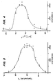
- the important relationship of nickel bath temperature control to hysteresis is illustrated in Figure 3 in which the hysteresis characteristics of rectangular samples from electroformed nickel articles prepared on 2.54 cm diameter stainless steel (304) mandrels in different electroforming baths maintained at pH 3.85 and nickel concentration of 71.7 g.1- 1 but held at different temperatures are plotted against the temperature of the bath in which each electroformed nickel article was made. A parting temperature of about 22°C was employed.
- the stress-strain hysteresis In order to remove an electroformed article from a core mandrel having a segmental cross-sectional area of less than about 11.6 cm 2 and an overall length to segmental cross-sectional area ratio greater than about 0.6, the stress-strain hysteresis must be at least about 0.00015.
- the preferred concentration of nickel for electroforming nickel articles should be between about 68.6 g.l-' and about 74.8 g.I- 1 with optimum being about 71.7 g.l -1 .
- the important relationship of nickel concentration control to hysteresis is illustrated in Figure 4 in which the hysteresis characteristics of rectangular samples from electroformed nickel articles prepared on 2.54 cm diameter stainless steel (304) mandrels in different electroforming baths maintained at pH 3.85 and temperature of 60°C but held at different nickel concentrations are plotted against the nickel concentration of the bath in which each electroformed nickel article was made. A parting temperature of about 22°C was employed.
- the stress-strain hysteresis In order to remove an electroformed article from a core mandrel having a segmental cross-sectional area of less than about 11.6 cm 2 and an,overall length to segmental cross-sectional area ratio greater than about 0.6, the stress-strain hysteresis must be at least about 0.00015.
- boric acid concentration drops below about 24.9 g.l -1 , bath control diminishes and surface flaws increase.
- the boric acid concentration is preferably maintained at about the saturation point at 38°C. Optimum hysteresis may be achieved with a boric acid concentration of about 31.2 g.l -1 .
- the boric acid concentration exceeds about 33.7 g.1- 1 , precipitation can occur in localised cold spots thereby interferring with the electroforming process.
- the surface tension of. the plating solution is adjusted to between about 0.033 and 0.037 N.m- 1 .
- the surface tension of the solution may be maintained within this range by adding an anionic surfactant such as sodium lauryl sulfate, sodium alcohol sulfate (Duponol 80, available from E. I. duPont de Nemours and Co., Inc.), sodium hydrocarbon sulfonate (Petrowet R, available from E. I. duPont de Nemours and Co., Inc.) and the like.
- an anionic surfactant such as sodium lauryl sulfate, sodium alcohol sulfate (Duponol 80, available from E. I. duPont de Nemours and Co., Inc.), sodium hydrocarbon sulfonate (Petrowet R, available from E. I. duPont de Nemours and Co., Inc.) and the like.
- Saccharine is a stress reliever. However, in a concentration of more than about 2 g.l-', it causes nickel oxide to form as a green powder rather than as a nickel deposit on core mandrels. At concentrations of about 1 g.1- 1 the deposited nickel layer will often become so compressively stressed that the stress will be relieved during deposition causing the deposit to be permanently wrinkled. Consequently, one cannot depend on adding large quantities of saccharine or other stress reducers to an electroforming bath to produce the desired parting gap. Additionally, saccharine renders the deposit brittle thus limiting its uses.
- the preferred current density is between about 3230 A.m- 2 and about 4300 A.m -2 .
- Higher current densities may be achieved by increasing the electrolyte flow, mandrel rotational speed, electrolyte agitation, and cooling. Current densities as high as 9680 Am-2 have been demonstrated.
- Parting conditions are also optimized by cooling the outer surface of the electroformed article rapidly to cool the entire deposited coating prior to any significant cooling and contracting of the core mandrel permanently deform the electroformed article.
- the rate of cooling should be sufficient to impart a stress in the electroformed article of between about 2750 and 5500 bar to permanently deform the electroformed article and to render the length of the inner perimeter of the electroformed article incapable of contracting to less than 0.04 percent greater than the length of the outer perimeter of the core mandrel after the core mandrel is cooled.
- the difference in temperature between the coating and the outer cooling medium must be sufficiently less than the difference in temperature between the cooling medium and the temperature of the core mandrel during the stretching phase of the process to achieve sufficient permanent deformation of the electroformed article.
- Nickel has a low specific heat capacity and a high thermal conductivity.
- the temperature of the electroformed article may be dropped to 4°C in less than 1 second whereas the mandrel itself requires 10 seconds to reach 4°C after immersion.
- an electroformed article cannot be removed from the mandrel by utilising a cooling medium surrounding the outer surface of the electroformed article where the mandrel has a segmental cross-sectional area of less than about 11.6 cm 2 and an overall length to segmental cross-sectional area ratio greater than about 0.6.
- the electroforming process of this invention may be conducted in any suitable electroforming device.
- a solid cylindrically shaped mandrel may be suspended vertically in an electroplating tank.
- the mandrel is constructed of electrically conductive material that is compatible with the metal plating solution.
- the mandrel may be made of stainless steel.
- the top edge of the mandrel may be masked off with a suitable non-conductive material, such as wax to prevent deposition.
- the mandrel may be of any suitable cross-section including circular, rectangular, triangular and the like.
- the electroplating tank is filled with a plating solution and the temperature of the plating solution is maintained at the desired temperature.
- the electroplating tank can contain an annular shaped anode basket which surrounds the mandrel and which is filled with metal chips.
- the anode basket is disposed in axial alignment with the mandrel.
- the mandrel is connected to a rotatable drive shaft driven by a motor.
- the drive shaft and motor may be supported by suitable support members.
- Either the mandrel or the support for the electroplating tank may be vertically and horizontally movable to allow the mandrel to be moved into and out of the electroplating solution.
- Electroplating current can be supplied to the electroplating tank from a suitable DC source.
- the positive end of the DC source can be connected to the anode basket and the negative end of the DC source connected to a brush and a brush/split ring arrangement on the drive shaft which supports and drives the mandrel.
- the electroplating current passes from the DC source to the anode basket, to the plating solution, the mandrel, the drive shaft, the split ring, the brush, and back to the DC source.
- the mandrel is lowered into the electroplating tank and continuously rotated about its vertical axis. As the mandrel rotates, a layer of electroformed metal is deposited on its outer surface. When the layer of deposited metal has reached the desired thickness, the mandrel is removed from the electroplating tank and immersed in a cold water bath.
- the temperature of the cold water bath should be between about 27°C and about 1°C.
- the deposited metal is cooled prior to any significant cooling and contracting of the solid mandrel to impart an internal stress of between about 2750 bar and about 5500 bar to the deposited metal. Since the metal cannot contract and is selected to have a stress-strain hysteresis of at least about 0.00015, it is permanently deformed so that after the core mandrel is cooled and contracted, the deposited metal article may be removed from the mandrel. The deposited metal article does not adhere to the mandrel since the mandrel is selected from a passive material. Consequently, as the mandrel shrinks after permanent deformation of the deposited metal, the deposited metal article may be readily slipped off the mandrel..
- a typical electrolytic cell for depositing metals such as nickel may comprise a tank containing a rotary drive means including a mandrel supporting drive hub centrally mounted thereon.
- the drive means may also provide a low resistance conductive element for conducting a relatively high amperage electrical current between the mandrel and a power supply.
- the cell is adapted to draw, for example, a peak current of about 3,000 amperes DC at a potential of about 18 volts.
- the mandrel comprises the cathode of the cell.
- An anode electrode for the electrolytic cell comprises an annular shaped bascket containing metallic nickel which replenishes the nickel electrodeposited out of the solution.
- the nickel used for the anode comprises sulfur depolarized nickel.
- Suitable sulfur depolarized nickel is available under the tradenames, "SD" Electrolytic Nickel and “S” Nickel Rounds from International Nickel Co.
- Non sulfur depolarized nickel can also be used such as carboyl nickel, electrolytic nickel and the like.
- the nickel may be in any suitable form or configuration. Typical shapes include buttons, chips, squares, strips and the like.
- the basket is supported within the cell by an annular shaped basket support member which also supports an electroforming solution distributor manifold or sparger which is adapted to introduce electroforming solution to the cell and effect agitation thereof.
- a relatively high amperage current path within the basket is provided through a contact terminal which is attached to a current supply bus bar.
- an article is electroformed by preheating a solid electrically conductive mandrel at a preheating station 10.
- Preheating is effected by contacting the mandrel with a nickel sulfamate solution at about 60°C for a sufficient period of time to bring the solid mandrel to about 60°C.
- Preheating in this manner allows the mandrel to expand to the dimensions desired in the electroforming zone 12 and enables the electroforming operation to begin as soon as the mandrel is placed in the electroforming zone 12. Thereafter, the mandrel is transported from preheating station 10 to an electroforming zone 12.
- the electroforming zone 12 comprises at least one cell containing an upstanding electrically conductive rotatable spindle which is centrally located within the cell and a concentrically located container spaced therefrom which contains donor metallic nickel.
- the cell is filled with nickel sulfamate electroforming solution.
- the mandrel is positioned on the upstanding electrically conductive rotatable spindle and is rotated thereon.
- a DC potential is applied between the rotating mandrel cathode and the donor metallic nickel anode for a sufficient period of time to effect electrodeposition of nickel on the mandrel to a predetermined thickness of at least 3 nm.
- the mandrel and the nickel belt formed thereon are transferred to a nickel sulfamate solution recovery zone 14.
- the electroformed article-bearing mandrel is transferred to a cooling zone 16 containing water maintained at about 4°C to 27°C or cooler for cooling the mandrel and the electroformed article whereby the electroformed article is rapidly cooled prior to any significant cooling and contracting of the solid mandrel whereby a stress of between about 2750 and 5500 bar are imparted to the cooled electroformed article to permanently deform the electroformed article and to render the length of the inner perimeter of the electroformed article incapable of contracting to less than about 0.4 percent greater than the length of the outer perimeter of the core mandrel after the core mandrel is cooled and contracted.
- the relatively electroformed articles by the present invention must have a stress-strain hysteresis of at least about 0.00015. Moreover, the electroformed article must have an internal stress of between about 6.9 bar and about 1030 bar compressive, i.e. to permit rapid parting of the electroformed'article from the mandrel. The electroformed article must have a thickness of at least about 3 nm in order to allow sufficient permanent deformation utilizing the stress-strain hysteresis characteristics of the electroformed article.
- Very high current densities are employed with a nickel sulfamate electroforming solution.
- the current densities range from about 1610 Am-2 to about 5380 Am-2, with a preferred current density of about 3230 Am-2.
- current concentrations range from about 23 to about 91 amps per litre.
- a flow rate of about 91 l.min- 1 of solution has been found sufficient to effect proper temperature control.
- the combined effect of mandrel rotation and solution impingement assures uniformity of composition and temperature of the electroforming solution within the electroforming cell.
- the composition of the aqueous nickel sulfamate solution within the electroforming zone should be as follows:
- a metal halide generally a nickel halide such as nickel chloride, nickel bromide, or nickel fluoride and preferably, nickel chloride, are included in the nickel sulfamate electroforming solution to avoid anode polarization.
- Anode polarization is evidenced by gradually increasing pH.
- the pH of the nickel electroforming solution should be between about 3.8 and about 3.9. At a pH of greater than about 4.1 surface flaws such as gas pitting increase. Also, internal stress increases and interfers with parting of the electroformed belt from the mandrel. At a pH of less than about 3.5, the metallic surface of the mandrel can become activated, especially when a chromium plated mandrel is employed, thereby causing the metal electroformed to adhere to the chromium plating. Low pH also results in lower tensile strength. The pH level may be maintained by the addition of an acid such as sulfamic acid, when necessary.
- Control of the pH range may also be assisted by the addition of a buffering agent such as boric acid within a range of about 24.9 g.l-' to about 31.2 g.l-'.
- a buffering agent such as boric acid within a range of about 24.9 g.l-' to about 31.2 g.l-'.
- the nickel sulfamate electroforming solution is continuously circulated through a closed solution treating loop as shown in Figure 5.
- This loop comprises a series of processing stations which maintain a steady state composition of the solution, regulate the temperature of the solution and remove any impurities therefrom.
- the electroforming cell 12 contains one wall thereof which is shorter than the others and acts as a weir over which the electroforming solution continuously overflows to a trough as recirculating solution is continuously pumped into the cell via the solution distributor manifold or sparger along the bottom of the cell.
- the solution flows from the electroforming cell 12 via a trough to an electropurification zone 20 and a solution sump 22.
- the solution is then pumped to a filtration zone 24 and to a heat exchange station 26 and is then recycled in purified condition at a desired temperature and composition to the electroplating cell 12 whereupon that mixture with the solution contained therein in a steady state condition set forth above is maintained on a continuous and stable basis.
- the electrolytic purification station 20 removes the dissolved noble metallic impurities from the nickel sulfamate solution prior to filtering.
- a metal plate of steel, or preferably stainless steel, can be mounted in station 20 to function as the cathode electrode.
- Anodes can be provided by a plurality of anode baskets which comprise tubular shaped metallic bodies, preferably titanium, each having a fabric anode bag.
- a DC potential is applied between the cathodes and the anodes of the purification station from a DC source.
- the electropurification station 20 includes a wall which extends coextensively with the wall of the solution sump zone 22 and functions as a weir.
- the solution can be replenished by the automatic addition of deionized water from a source 28 and/or by recycling solution from the nickel rinse zone 14 to sump 22 via line 30.
- a pH meter can be positioned in sump 22 for sensing the pH of the solution and for effecting the addition of an acid such as sulfamic acid when necessary to maintain essentially constant pH.
- the continuous addition of stress reducing agents can be effected at sump 22 via line 32. Also, control of the surface tension of the solution can be maintained by continuous addition of surfactant to the sump via line 34.
- the electroforming solution which flows from the cell 12 is raised in temperature due to the flow of relatively large currents therein and accompanying generation of heat in the electroforming cell.
- Means may be provided at the heat exchanging station 26 for cooling the electroforming solution to a lower temperature.
- the heat exchanger may be of any conventional design which receives a coolant such as chilled water from a cooling or refrigerating system (not shown).
- the electroplating solution which is cooled in the heat exchanger means can be successively pumped to a second heat exchanger which can increase the temperature of the cool solution to within relatively close limits of the desired temperature.
- the second heat exchanger can be heated by steam derived from a steam generator (not shown).
- the first cooling heat exchanger can, for example, cool the relatively warm solution from a temperature of about 63°C or above to a temperature of about 57°C.
- a second warming heat exchange can heat the solution to a temperature of 60°C.
- the efflux from the heat exchange station 26 is pumped to the electroforming cell 12.
- the bath parameters such as the addition of enhancers, altering pH, changing the temperatures, adjusting the cation concentration of the electroforming bath, regulating current density
- the conditions are experimentally altered until a deposited electroformed article is characterised by a stress-strain hysteresis of at least about 0.00015.
- the relative quantity of enhancers such as saccharine, methylbenzene sulfonamide, the pH, the bath temperature, the nickel cation concentration, and the current density may be adjusted to achieve a stress-strain hysteresis of at least about 0.00015.
- Current density affects the pH and the nickel concentration.
- the nickel is unable to reach the surface of the core mandrel at a sufficient rate and the 1/2 cell voltage increases and hydrogen ions deposit thereby increasing the hydroxyl ions remaining in the bath thereby increasing the pH.
- the 1/2 cell voltage is the potential required to change a nickel ion (Ni++) to nickel metal (Ni), or vice versa, at infinite dilution and zero current density.
- increasing the current density also increases the bath temperature.
- the electroformed coating should have a thickness of at least about 3 nm and a stress strain hysteresis of at least about 0.00015.
- the exposed surface of the electroformed article on the mandrel must be rapidly cooled prior to any significant cooling and contracting of the core mandrel.
Landscapes
- Chemical & Material Sciences (AREA)
- Engineering & Computer Science (AREA)
- Chemical Kinetics & Catalysis (AREA)
- Electrochemistry (AREA)
- Materials Engineering (AREA)
- Metallurgy (AREA)
- Organic Chemistry (AREA)
- Moulds For Moulding Plastics Or The Like (AREA)
- Electroplating Methods And Accessories (AREA)
- Discharge Lamps And Accessories Thereof (AREA)
- Transition And Organic Metals Composition Catalysts For Addition Polymerization (AREA)
- Organic Insulating Materials (AREA)
- Glass Compositions (AREA)
Claims (9)
Applications Claiming Priority (2)
| Application Number | Priority Date | Filing Date | Title |
|---|---|---|---|
| US624164 | 1984-06-25 | ||
| US06/624,164 US4501646A (en) | 1984-06-25 | 1984-06-25 | Electroforming process |
Publications (3)
| Publication Number | Publication Date |
|---|---|
| EP0166495A2 EP0166495A2 (de) | 1986-01-02 |
| EP0166495A3 EP0166495A3 (en) | 1987-05-20 |
| EP0166495B1 true EP0166495B1 (de) | 1990-03-07 |
Family
ID=24500918
Family Applications (1)
| Application Number | Title | Priority Date | Filing Date |
|---|---|---|---|
| EP85300191A Expired - Lifetime EP0166495B1 (de) | 1984-06-25 | 1985-01-11 | Elektroformungsverfahren |
Country Status (6)
| Country | Link |
|---|---|
| US (1) | US4501646A (de) |
| EP (1) | EP0166495B1 (de) |
| JP (1) | JPH079075B2 (de) |
| KR (1) | KR920002712B1 (de) |
| CA (1) | CA1239611A (de) |
| DE (1) | DE3576367D1 (de) |
Families Citing this family (39)
| Publication number | Priority date | Publication date | Assignee | Title |
|---|---|---|---|---|
| US4678691A (en) * | 1985-10-24 | 1987-07-07 | Xerox Corporation | Electroforming process and product |
| US4747992A (en) * | 1986-03-24 | 1988-05-31 | Sypula Donald S | Process for fabricating a belt |
| US4781799A (en) * | 1986-12-08 | 1988-11-01 | Xerox Corporation | Electroforming apparatus and process |
| US4786376A (en) * | 1988-01-05 | 1988-11-22 | The United States Of America As Represented By The Secretary Of The Air Force | Electrodeposition without internal deposit stress |
| US4902386A (en) * | 1989-08-02 | 1990-02-20 | Xerox Corporation | Electroforming mandrel and method of fabricating and using same |
| US5127885A (en) * | 1990-12-24 | 1992-07-07 | Xerox Corporation | Endless metal belt with strengthened edges |
| US5049243A (en) * | 1990-12-24 | 1991-09-17 | Xerox Corporation | Electroforming process for multi-layer endless metal belt assembly |
| US5131893A (en) * | 1990-12-24 | 1992-07-21 | Xerox Corporation | Endless metal belt assembly with minimized contact friction |
| US5049242A (en) * | 1990-12-24 | 1991-09-17 | Xerox Corporation | Endless metal belt assembly with controlled parameters |
| US5221458A (en) * | 1990-12-24 | 1993-06-22 | Xerox Corporation | Electroforming process for endless metal belt assembly with belts that are increasingly compressively stressed |
| US5152723A (en) * | 1990-12-24 | 1992-10-06 | Xerox Corporation | Endless metal belt assembly with hardened belt surfaces |
| US5160421A (en) * | 1991-12-02 | 1992-11-03 | Xerox Corporation | Electroforms with high dimensional stability |
| US5316651A (en) * | 1991-12-03 | 1994-05-31 | Xerox Corporation | Process for preparing selectively stressed endless belts |
| US5230787A (en) * | 1991-12-30 | 1993-07-27 | Xerox Corporation | Spring and process for making a spring for a fluid bearing by electroforming |
| US5298956A (en) * | 1992-10-07 | 1994-03-29 | Xerox Corporation | Reinforced seamless intermediate transfer member |
| JP3292329B2 (ja) * | 1992-10-16 | 2002-06-17 | ゼロックス・コーポレーション | 静電写真システムの中間転写部材 |
| US5840170A (en) * | 1992-11-30 | 1998-11-24 | Gould Electronics Inc. | Method for inhibiting the electrodeposition of organic particulate matter on copper foil |
| US6007692A (en) * | 1993-04-05 | 1999-12-28 | Xerox Corporation | Electroforming mandrels with contoured surfaces |
| US5254239A (en) * | 1993-04-26 | 1993-10-19 | Xerox Corporation | Mask stripper for electroform parting |
| US5395499A (en) * | 1993-05-14 | 1995-03-07 | Xerox Corporation | Electroforming mandrels |
| US5572782A (en) * | 1993-12-01 | 1996-11-12 | Xerox Corporation | Flexible belt assembly |
| CA2118332A1 (en) * | 1993-12-09 | 1995-06-10 | Thomas J. Behe | Back up roll with negative wrap |
| US5524342A (en) * | 1994-05-27 | 1996-06-11 | Xerox Corporation | Methods for shrinking nickel articles |
| US5543028A (en) * | 1994-11-23 | 1996-08-06 | Xerox Corporation | Electroforming semi-step carousel, and process for using the same |
| US5500105A (en) * | 1994-12-01 | 1996-03-19 | Xerox Corporation | Bowed shape electroforms |
| US5908285A (en) * | 1995-03-10 | 1999-06-01 | United Technologies Corporation | Electroformed sheath |
| US5709586A (en) * | 1995-05-08 | 1998-01-20 | Xerox Corporation | Honed mandrel |
| US5752144A (en) * | 1996-04-01 | 1998-05-12 | Xerox Corporation | Method of fabricating a reclaimable uniform conditioning blotter roll |
| US5807472A (en) * | 1997-01-13 | 1998-09-15 | Xerox Corporation | Parting fixture for removal of a substrate from a mandrel |
| US5762736A (en) * | 1997-01-21 | 1998-06-09 | Xerox Corporation | Frozen material assisted electroform separation method |
| US5723037A (en) * | 1997-02-03 | 1998-03-03 | Xerox Corporation | Magnetic force assisted electroform separation method |
| US6376088B1 (en) | 1999-11-24 | 2002-04-23 | Xerox Corporation | Non-magnetic photoreceptor substrate and method of making a non-magnetic photoreceptor substrate |
| US6454978B1 (en) | 2000-06-16 | 2002-09-24 | Avery Dennison Corporation | Process for making fuel cell plates |
| US6500367B2 (en) | 2000-12-28 | 2002-12-31 | Xerox Corporation | Method of forming a seamless belt |
| GB0106044D0 (en) * | 2001-03-12 | 2001-05-02 | Giantcode Tools As | Composite mandrel |
| US8012329B2 (en) * | 2008-05-09 | 2011-09-06 | 3M Innovative Properties Company | Dimensional control in electroforms |
| US8672634B2 (en) | 2010-08-30 | 2014-03-18 | United Technologies Corporation | Electroformed conforming rubstrip |
| US12430531B2 (en) * | 2023-01-03 | 2025-09-30 | Giesecke+Devrient ePayments GmbH | Method of manufacturing a card-shaped data carrier and lamination plate therefor |
| CN117385421A (zh) * | 2023-08-07 | 2024-01-12 | 南京航空航天大学 | 基于铝芯模的电铸方法 |
Family Cites Families (13)
| Publication number | Priority date | Publication date | Assignee | Title |
|---|---|---|---|---|
| GB239977A (en) * | 1924-07-24 | 1925-09-24 | Thomas William Stainer Hutchin | Improvements relating to the electro deposition of metals |
| JPS528774B1 (de) * | 1970-01-30 | 1977-03-11 | ||
| US3905400A (en) * | 1970-11-13 | 1975-09-16 | Xerox Corp | Electroforming mandrel |
| CA1018932A (en) * | 1972-05-08 | 1977-10-11 | Raymond E. Bailey | Dynamic bath control process for forming seamless nickel belt |
| US3876510A (en) * | 1972-05-08 | 1975-04-08 | Xerox Corp | Process for electroforming a flexible belt |
| GB1421818A (en) * | 1972-05-08 | 1976-01-21 | Xerox Corp | Nickel electroforming process |
| US3927463A (en) * | 1972-06-23 | 1975-12-23 | Xerox Corp | Method of making a cylindrically shaped, hollow electroforming mandrel |
| US3950839A (en) * | 1972-06-23 | 1976-04-20 | Xerox Corporation | Method of making an electroforming mandrel |
| DE2335206A1 (de) * | 1973-07-11 | 1975-01-30 | Kabel Metallwerke Ghh | Verfahren zur herstellung eines weitverkehrsrundhohlleiters |
| US3963587A (en) * | 1975-05-19 | 1976-06-15 | Xerox Corporation | Process for electroforming nickel foils |
| JPS528774A (en) * | 1975-07-10 | 1977-01-22 | Nec Corp | Semiconductor device |
| US4067782A (en) * | 1977-05-09 | 1978-01-10 | Xerox Corporation | Method of forming an electroforming mandrel |
| US4326928A (en) * | 1981-01-26 | 1982-04-27 | General Dynamics, Pomona Division | Method of electroforming |
-
1984
- 1984-06-25 US US06/624,164 patent/US4501646A/en not_active Expired - Lifetime
- 1984-12-29 KR KR1019840008519A patent/KR920002712B1/ko not_active Expired
-
1985
- 1985-01-03 CA CA000471401A patent/CA1239611A/en not_active Expired
- 1985-01-11 EP EP85300191A patent/EP0166495B1/de not_active Expired - Lifetime
- 1985-01-11 DE DE8585300191T patent/DE3576367D1/de not_active Expired - Fee Related
- 1985-01-14 JP JP60004838A patent/JPH079075B2/ja not_active Expired - Lifetime
Also Published As
| Publication number | Publication date |
|---|---|
| US4501646A (en) | 1985-02-26 |
| KR920002712B1 (ko) | 1992-03-31 |
| EP0166495A3 (en) | 1987-05-20 |
| EP0166495A2 (de) | 1986-01-02 |
| DE3576367D1 (de) | 1990-04-12 |
| CA1239611A (en) | 1988-07-26 |
| KR860000418A (ko) | 1986-01-28 |
| JPS619591A (ja) | 1986-01-17 |
| JPH079075B2 (ja) | 1995-02-01 |
Similar Documents
| Publication | Publication Date | Title |
|---|---|---|
| US4501646A (en) | Electroforming process | |
| US4781799A (en) | Electroforming apparatus and process | |
| US3844906A (en) | Dynamic bath control process | |
| US4664758A (en) | Electroforming process | |
| US4568431A (en) | Process for producing electroplated and/or treated metal foil | |
| CN100564606C (zh) | 金属薄膜连续电沉积装置及其方法 | |
| JP3174047B2 (ja) | 導電性発泡体の連続的電気メッキ法 | |
| US3954568A (en) | Electroforming an endless flexible seamless xerographic belt | |
| BRPI0621567A2 (pt) | processo de galvanoplastia de espuma e aparelho | |
| KR20010022951A (ko) | 니켈-철 합금 박판 제조장치 및 니켈-철 (80-20)합금 박판의 제조방법 | |
| US3799859A (en) | Electroforming system | |
| JPS61119699A (ja) | 金属または金属合金の箔を製造するシステム並びに方法 | |
| KR950002055B1 (ko) | 전착(electrodeposition)에 의해 기판상에 니켈인 합금막을 형성하는 방법, 이 방법에 의해 형성된 니켈인 합금막 및 니켈인 합금박 오리피스 플레이트 | |
| FR2646174A1 (fr) | Procede et dispositif de revetement en continu de substrats conducteurs de l'electricite par electrolyse a grande vitesse | |
| EP0223425B1 (de) | Verfahren zur Elektroformung und nach dem Verfahren erhaltene Gegenstände | |
| US3876510A (en) | Process for electroforming a flexible belt | |
| US5385660A (en) | Dendritic growth assisted electroform separation | |
| US6004447A (en) | Electroforming process | |
| US5221458A (en) | Electroforming process for endless metal belt assembly with belts that are increasingly compressively stressed | |
| US4118301A (en) | Apparatus for electrochemical finishing of stainless steel | |
| US5543028A (en) | Electroforming semi-step carousel, and process for using the same | |
| US5807472A (en) | Parting fixture for removal of a substrate from a mandrel | |
| JP2943484B2 (ja) | アルミニウムの溶融塩めっき方法と装置 | |
| US1787139A (en) | Process of forming iron foils | |
| US5480528A (en) | Brushless electrodeposition apparatus |
Legal Events
| Date | Code | Title | Description |
|---|---|---|---|
| PUAI | Public reference made under article 153(3) epc to a published international application that has entered the european phase |
Free format text: ORIGINAL CODE: 0009012 |
|
| AK | Designated contracting states |
Designated state(s): DE FR GB |
|
| PUAL | Search report despatched |
Free format text: ORIGINAL CODE: 0009013 |
|
| AK | Designated contracting states |
Kind code of ref document: A3 Designated state(s): DE FR GB |
|
| 17P | Request for examination filed |
Effective date: 19871028 |
|
| 17Q | First examination report despatched |
Effective date: 19880922 |
|
| GRAA | (expected) grant |
Free format text: ORIGINAL CODE: 0009210 |
|
| AK | Designated contracting states |
Kind code of ref document: B1 Designated state(s): DE FR GB |
|
| REF | Corresponds to: |
Ref document number: 3576367 Country of ref document: DE Date of ref document: 19900412 |
|
| ET | Fr: translation filed | ||
| PLBE | No opposition filed within time limit |
Free format text: ORIGINAL CODE: 0009261 |
|
| STAA | Information on the status of an ep patent application or granted ep patent |
Free format text: STATUS: NO OPPOSITION FILED WITHIN TIME LIMIT |
|
| 26N | No opposition filed | ||
| PGFP | Annual fee paid to national office [announced via postgrant information from national office to epo] |
Ref country code: DE Payment date: 19991231 Year of fee payment: 16 |
|
| PGFP | Annual fee paid to national office [announced via postgrant information from national office to epo] |
Ref country code: GB Payment date: 20000105 Year of fee payment: 16 |
|
| PGFP | Annual fee paid to national office [announced via postgrant information from national office to epo] |
Ref country code: FR Payment date: 20000112 Year of fee payment: 16 |
|
| PG25 | Lapsed in a contracting state [announced via postgrant information from national office to epo] |
Ref country code: GB Free format text: LAPSE BECAUSE OF NON-PAYMENT OF DUE FEES Effective date: 20010111 |
|
| GBPC | Gb: european patent ceased through non-payment of renewal fee |
Effective date: 20010111 |
|
| PG25 | Lapsed in a contracting state [announced via postgrant information from national office to epo] |
Ref country code: FR Free format text: LAPSE BECAUSE OF NON-PAYMENT OF DUE FEES Effective date: 20010928 |
|
| PG25 | Lapsed in a contracting state [announced via postgrant information from national office to epo] |
Ref country code: DE Free format text: LAPSE BECAUSE OF NON-PAYMENT OF DUE FEES Effective date: 20011101 |
|
| REG | Reference to a national code |
Ref country code: FR Ref legal event code: ST |