EP0166621A2 - Technique de fabrication d'un câble à fibres optiques - Google Patents
Technique de fabrication d'un câble à fibres optiques Download PDFInfo
- Publication number
- EP0166621A2 EP0166621A2 EP85304621A EP85304621A EP0166621A2 EP 0166621 A2 EP0166621 A2 EP 0166621A2 EP 85304621 A EP85304621 A EP 85304621A EP 85304621 A EP85304621 A EP 85304621A EP 0166621 A2 EP0166621 A2 EP 0166621A2
- Authority
- EP
- European Patent Office
- Prior art keywords
- tube
- strip
- optical fibre
- die
- fibre
- Prior art date
- Legal status (The legal status is an assumption and is not a legal conclusion. Google has not performed a legal analysis and makes no representation as to the accuracy of the status listed.)
- Withdrawn
Links
- 239000013307 optical fiber Substances 0.000 title claims abstract description 72
- 238000000034 method Methods 0.000 title claims abstract description 27
- 238000004519 manufacturing process Methods 0.000 title claims description 21
- 239000000835 fiber Substances 0.000 claims abstract description 89
- 229910052751 metal Inorganic materials 0.000 claims abstract description 16
- 239000002184 metal Substances 0.000 claims abstract description 16
- 229910001092 metal group alloy Inorganic materials 0.000 claims abstract description 14
- 239000003566 sealing material Substances 0.000 claims description 20
- 238000007789 sealing Methods 0.000 claims description 14
- 230000003287 optical effect Effects 0.000 claims description 3
- 238000011144 upstream manufacturing Methods 0.000 claims 2
- 230000008569 process Effects 0.000 abstract description 3
- 239000000463 material Substances 0.000 description 29
- 229910000679 solder Inorganic materials 0.000 description 9
- 229910045601 alloy Inorganic materials 0.000 description 7
- 239000000956 alloy Substances 0.000 description 7
- 230000000712 assembly Effects 0.000 description 5
- 238000000429 assembly Methods 0.000 description 5
- 230000004907 flux Effects 0.000 description 5
- 239000003365 glass fiber Substances 0.000 description 5
- 229910000881 Cu alloy Inorganic materials 0.000 description 4
- 230000005540 biological transmission Effects 0.000 description 4
- 230000015572 biosynthetic process Effects 0.000 description 4
- 244000309464 bull Species 0.000 description 4
- 239000000314 lubricant Substances 0.000 description 4
- 230000002829 reductive effect Effects 0.000 description 4
- 238000013459 approach Methods 0.000 description 3
- 230000008901 benefit Effects 0.000 description 3
- 239000004020 conductor Substances 0.000 description 3
- 238000010276 construction Methods 0.000 description 3
- 230000005499 meniscus Effects 0.000 description 3
- 239000004033 plastic Substances 0.000 description 3
- 229920003023 plastic Polymers 0.000 description 3
- 230000001681 protective effect Effects 0.000 description 3
- 238000010791 quenching Methods 0.000 description 3
- 230000000171 quenching effect Effects 0.000 description 3
- RYGMFSIKBFXOCR-UHFFFAOYSA-N Copper Chemical compound [Cu] RYGMFSIKBFXOCR-UHFFFAOYSA-N 0.000 description 2
- 239000004593 Epoxy Substances 0.000 description 2
- CWYNVVGOOAEACU-UHFFFAOYSA-N Fe2+ Chemical compound [Fe+2] CWYNVVGOOAEACU-UHFFFAOYSA-N 0.000 description 2
- 239000004677 Nylon Substances 0.000 description 2
- 239000004698 Polyethylene Substances 0.000 description 2
- 238000005219 brazing Methods 0.000 description 2
- 238000004891 communication Methods 0.000 description 2
- 230000006835 compression Effects 0.000 description 2
- 238000007906 compression Methods 0.000 description 2
- 229910052802 copper Inorganic materials 0.000 description 2
- 239000010949 copper Substances 0.000 description 2
- 238000011161 development Methods 0.000 description 2
- 230000018109 developmental process Effects 0.000 description 2
- 230000000694 effects Effects 0.000 description 2
- 238000001125 extrusion Methods 0.000 description 2
- 239000000945 filler Substances 0.000 description 2
- 238000010438 heat treatment Methods 0.000 description 2
- 238000003780 insertion Methods 0.000 description 2
- 230000037431 insertion Effects 0.000 description 2
- 230000000670 limiting effect Effects 0.000 description 2
- 230000007246 mechanism Effects 0.000 description 2
- 238000012986 modification Methods 0.000 description 2
- 230000004048 modification Effects 0.000 description 2
- 229920001778 nylon Polymers 0.000 description 2
- 230000000704 physical effect Effects 0.000 description 2
- -1 polyethylene Polymers 0.000 description 2
- 229920000573 polyethylene Polymers 0.000 description 2
- XLYOFNOQVPJJNP-UHFFFAOYSA-N water Substances O XLYOFNOQVPJJNP-UHFFFAOYSA-N 0.000 description 2
- 238000004804 winding Methods 0.000 description 2
- 239000004642 Polyimide Substances 0.000 description 1
- BQCADISMDOOEFD-UHFFFAOYSA-N Silver Chemical compound [Ag] BQCADISMDOOEFD-UHFFFAOYSA-N 0.000 description 1
- ATJFFYVFTNAWJD-UHFFFAOYSA-N Tin Chemical compound [Sn] ATJFFYVFTNAWJD-UHFFFAOYSA-N 0.000 description 1
- QCWXUUIWCKQGHC-UHFFFAOYSA-N Zirconium Chemical compound [Zr] QCWXUUIWCKQGHC-UHFFFAOYSA-N 0.000 description 1
- 238000005299 abrasion Methods 0.000 description 1
- 238000009825 accumulation Methods 0.000 description 1
- NIXOWILDQLNWCW-UHFFFAOYSA-N acrylic acid group Chemical group C(C=C)(=O)O NIXOWILDQLNWCW-UHFFFAOYSA-N 0.000 description 1
- 229910052787 antimony Inorganic materials 0.000 description 1
- 230000004888 barrier function Effects 0.000 description 1
- 230000015556 catabolic process Effects 0.000 description 1
- 239000000919 ceramic Substances 0.000 description 1
- 230000008859 change Effects 0.000 description 1
- 239000011248 coating agent Substances 0.000 description 1
- 238000000576 coating method Methods 0.000 description 1
- 239000002131 composite material Substances 0.000 description 1
- 229920001577 copolymer Polymers 0.000 description 1
- 230000008878 coupling Effects 0.000 description 1
- 238000010168 coupling process Methods 0.000 description 1
- 238000005859 coupling reaction Methods 0.000 description 1
- 230000003247 decreasing effect Effects 0.000 description 1
- 230000007812 deficiency Effects 0.000 description 1
- 238000006731 degradation reaction Methods 0.000 description 1
- 230000000593 degrading effect Effects 0.000 description 1
- 239000003989 dielectric material Substances 0.000 description 1
- 230000003292 diminished effect Effects 0.000 description 1
- 229920001971 elastomer Polymers 0.000 description 1
- 238000005538 encapsulation Methods 0.000 description 1
- 239000002657 fibrous material Substances 0.000 description 1
- 239000011521 glass Substances 0.000 description 1
- 229920001903 high density polyethylene Polymers 0.000 description 1
- 239000004700 high-density polyethylene Substances 0.000 description 1
- 238000009434 installation Methods 0.000 description 1
- LQBJWKCYZGMFEV-UHFFFAOYSA-N lead tin Chemical compound [Sn].[Pb] LQBJWKCYZGMFEV-UHFFFAOYSA-N 0.000 description 1
- 239000011159 matrix material Substances 0.000 description 1
- 239000007769 metal material Substances 0.000 description 1
- 230000036961 partial effect Effects 0.000 description 1
- 229920001084 poly(chloroprene) Polymers 0.000 description 1
- 229920001721 polyimide Polymers 0.000 description 1
- 229920002635 polyurethane Polymers 0.000 description 1
- 239000004814 polyurethane Substances 0.000 description 1
- 238000012545 processing Methods 0.000 description 1
- 239000005060 rubber Substances 0.000 description 1
- 229910052709 silver Inorganic materials 0.000 description 1
- 239000004332 silver Substances 0.000 description 1
- 229920001187 thermosetting polymer Polymers 0.000 description 1
- 229920002554 vinyl polymer Polymers 0.000 description 1
- 229910052726 zirconium Inorganic materials 0.000 description 1
Images


Classifications
-
- G—PHYSICS
- G02—OPTICS
- G02B—OPTICAL ELEMENTS, SYSTEMS OR APPARATUS
- G02B6/00—Light guides; Structural details of arrangements comprising light guides and other optical elements, e.g. couplings
-
- G—PHYSICS
- G02—OPTICS
- G02B—OPTICAL ELEMENTS, SYSTEMS OR APPARATUS
- G02B6/00—Light guides; Structural details of arrangements comprising light guides and other optical elements, e.g. couplings
- G02B6/44—Mechanical structures for providing tensile strength and external protection for fibres, e.g. optical transmission cables
- G02B6/4479—Manufacturing methods of optical cables
- G02B6/4486—Protective covering
- G02B6/4488—Protective covering using metallic tubes
-
- Y—GENERAL TAGGING OF NEW TECHNOLOGICAL DEVELOPMENTS; GENERAL TAGGING OF CROSS-SECTIONAL TECHNOLOGIES SPANNING OVER SEVERAL SECTIONS OF THE IPC; TECHNICAL SUBJECTS COVERED BY FORMER USPC CROSS-REFERENCE ART COLLECTIONS [XRACs] AND DIGESTS
- Y10—TECHNICAL SUBJECTS COVERED BY FORMER USPC
- Y10T—TECHNICAL SUBJECTS COVERED BY FORMER US CLASSIFICATION
- Y10T29/00—Metal working
- Y10T29/49—Method of mechanical manufacture
- Y10T29/49826—Assembling or joining
- Y10T29/49888—Subsequently coating
Definitions
- the present invention relates to a process and apparatus for fabricating optical fiber communication cables.
- a draw forming technique for manufacturing tubular, armored optical fiber cables has been developed.
- a metallic armor or containment tube is fabricated about one or more optical fibers by pulling a metal or metal alloy tape through at least one tube forming die and inserting one or more optical fibers into the forming tube.
- U.S. Patent Nos. 4,479,702, to Pryor et al. and 4,477,147, to Winter et al. illustrate this technique and several variations thereon.
- the present invention substantially reduces the risk of significantly increasing attenuation in the fiber or fibers as a result of tube springback. This is accomplished by applying a back tension of predetermined magnitude to each optical fiber as it is fed into the tube forming apparatus. By carefully controlling the back tension force applied to each fiber, the back tensional strain on each fiber may be adjusted to substantially compensate for the compressional strain induced by tube springback. By using the present invention, the net strain on the each fiber after fabrication is approximately zero and substantially no increase in light attenuation is caused.
- a metal or metal alloy tape is payed off a reel and pulled through at least one die to form the armor tube. While the tape is being formed into the tube, at least-one optical fiber is payed off a reel, wound about an accumulator and fed into the forming tube.
- the tension force required to pull the tape through each die is preferably provided by wrapping the optical fiber cable assembly about a driven capstan or bull block. After the cable assembly exits the capstan or bull block, it preferably passes through a station for sealing the tube seam. Thereafter, the cable assembly is finally wound upon a take-up reel.
- the accumulator is used to apply a desired back tension to the fiber or fibers.
- the number of fiber windings about the sheaves of the accumulator and the load applied to each sheave determine the back tension applied to each fiber.
- a plurality of accumulators may be used to apply the same or different back tensions to the fibers.
- a system 10 for fabricating an optical fiber cable core assembly 11 in accordance with the present invention is illustrated.
- a metal or metal alloy tape 12 from which the armor or containment tube 14 is formed is payed off.
- the accumulator 16 permits accumulation of a length of tape 12 sufficient to assure a substantially constant tape delivery rate to all downstream apparatus.
- the accumulator 16 may comprise any conventional accumulator known in the art.
- the tape 12 comprises a continuous strip of a metal or metal alloy possessing a desired set of physical properties.
- the desirability of various physical properties depends upon the application for the cable assembly.
- the tape material should possess high strength and high electrical conductivity.
- the tape material may be a very high strengtn, low conductivity material.
- strength is the paramount consideration. Consequently, it is desirable for the tape material to have a relatively high yield strength.
- Other desirable properties include good resistance to softening upon short term exposure to elevated temperatures and the ability to sustain coiling forces during fabrication and installation.
- the tape material has a conductivity in the range of 2X to 102% IACS, a yield strength of at least 30 ksi (207 MPa), most preferably at least 50 ksi (345 MPa), a yield strain in the range of 0.15% to 1%, most preferably from 0.3 to 0.95% and a diameter- to-thickness ratio of from 3:1 to 25:1, preferably from 4:1 to- 20:1.
- the term yield strain is the strain at the yield strength at 0.2% offset.
- Suitable copper base alloys include a high copper alloy containing zirconium produced by Olin Corporation and designated Copper Alloy 151, alloy C15500, alloy C19400, alloy C19500, alloy C63800 and alloy C68800.
- the tape material may have any desired cross-sectional shape.
- the tape 12 may have a rectangular cross-sectional shape.
- the tape width should be at least about equal to the outer circumference or periphery of the desired armoring construction.
- the tape material 12 has a trapezoidal cross-section. It has been discovered that a tape material having such a cross-sectional shape is subjected to reduced forces and stresses when pulled through one or more tube forming dies.
- a tape 12 having a transverse cross-sectional area which exceeds the desired transverse cross-sectional area of the armoring 14 by about 5% to about,20%, preferably by about 8% to about 17% and most preferably by about 10% to about 15%.
- the tape material prefferably has sufficient hardness and/or ductility to enable it to be formed into a hollow tubular member by being drawn through one or more forming dies. Accordingly, the tape material should be in a wrought and partially work hardened condition. Preferably, the tape material is at least about 1/4 hard and most preferably at least about full hard.
- the tape 12 is formed into the armoring tube 14 by pulling or drawing the tape through at least one tube forming die.
- tube forming approach high draw stresses develop in the metallic tube on the tube side or exit side of the forming die or dies as a result of the forming energy being transmitted by a tensional pulling force.
- the tube 14 When this pulling force is released or relaxed, the tube 14 generally becomes shorter due to elastic springback.
- the greater the strength of the metallic tube material the greater the springback.
- springback of the armor tube often transmits a permanent compressional strain to the optical fiber(s).
- the degree of compressional strain imparted to each optical fiber is a function of the amount of springback. In some instances, the compressional strain imparted to each fiber may increase fiber attenuation to unacceptable levels that interfere with light transmission.
- the risk of transmitting a permanent compressional strain to the fiber(s) that increases fiber attentuation to unacceptable levels is significantly reduced and substantially eliminated. This is accomplished by applying to each optical fiber a pre-determined back tension force that induces in each fiber a back tensional strain that substantially compensates for springback-induced compressional strain.
- the back tension force needed to compensate for springback induced compressional strain may be determined in the following manner.
- the draw stresses ⁇ T exerted on the forming tube are a function of the applied tube forming draw force P T , the tube outside diameter D OD , and the tube inside diameter DID.
- the relationship between these parameters may be expressed as follows:
- the elastic tension strain ⁇ T of the tube on the exit side of the tube forming die is a function of the draw stress ⁇ T and the elastic modulus E A of the tube material. The relationship is as follows:
- the back tension force P F that should be applied to each optical fiber as it enters the forming die is a function of the fiber stress OF and the fiber cross-sectional area.
- the back tensidn force that needs to be applied to each fiber can be determined for a known applied draw force. While it is preferred to apply to each fiber the back tension magnitude defined by equation (7), it has been found that satisfactory results can also be achieved using a back tension have a magnitude within +20%, preferably within +5%, of the back tension magnitude defined by equation (7).
- the back tension force is applied to each optical fiber by an accumulator 20 about which it is wound.
- the optical fiber or fibers 18 or 18'to be inserted into the armor tube 14 may comprise any commercially available buffered optical fiber.
- such an optical fiber consists of optical grade glass having an approximate diameter of about 0.001" (25um) coated by one or more layers of a buffered material such as nylon, polyvinyl formal, fluoroethylene- propylene copolymers, polyetylene, other acrylic materials and a coating sold under the trademark HYTREL by duPont.
- optical fiber capable of withstanding exposure to temperatures as high as 260°C for about 1 second in a limited atmosphere without seriously degrading. While it is preferred to encapsulate a.buffered optical fiber or fibers, the present technique also extends to the encapsulation of non-buffered optical fibers and optical fibers having a ceramic or other organic barrier layer.
- Each optical fiber 18, 18' is payed off a reel 19 and wound or wrapped about the reels or sheaves 21 and 23 of an accumulator 20 or 20'. From the accumulator 20, the fiber 18 is fed into a tube forming and cable assembling station 24. A pull force is applied to the fiber 18, 18' in a manner described more fully hereinafter to pull the fiber or fibers through the station 24.
- the back tension applied to the fiber 18, 18' by its accumulator 20, 20' is a function of the number of fiber turns about the sheaves 21, 21', 23, and 23', and the load 25, 25' applied to the sheave 21, 21' and/or the sheave 23, 23'.
- a load necessary to achieve the desired back tension magnitude is applied to the sheave 23, 23'.
- Any suitable means (not shown) known in the art may be used to apply the load to the sheave 23, 23'.
- a small weight may be suspended from the sheave.
- the accumulator 20 and/or 20' may comprise any conventional accumulator known in the art.
- the accumulator 20, 20' has several other purposes. First, it assures that there is sufficient slack in the optical fiber to avoid the formation of kinks or snags that may seriously damage the optical fiber. Second, it assures that there is a sufficient supply of optical fiber to travel along with the tape 12 and the cable assembly 11 as it is formed.
- Figure 1 primarily illustrates a single optical fiber'18 being fed into the tube forming and cable assembly 24, more than one optical fiber may be encapsulated within a single tube 14.
- the fibers may be inserted separately or as a preformed composite e.g. a rope of optical fibers.
- each fiber 18 or 18' is fed off its own reel 19 and wound about its own accumulator 20 or 20'. By winding each fiber about a separate accumulator, it is possible to apply different back tensions to the fibers. Different back tensions may be needed if optical fibers formed from different materials are to be encapsulated within a single tube.
- the metallic tape 12 is first drawn or pulled through a fluxing station 22.
- the fluxing station 22 may comprise any suitable flux applying apparatus known in the art.
- the fluxing station 22 applies a small amount of flux lubricant preferably to that tape surface which contacts the tube forming apparatus and forms the outer periphery of the tube 14.
- the flux lubricant primarily minimizes the friction created during the tube forming operation. In addition, it protects the surface forming the outer periphery of the tube 14 so that its solderability is not diminished. While any suitable flux lubricant known in the art may be used, it is preferred to use a flux lubricant that is water soluble so that it can be easily removed later on.
- the tape 12 After passing through the fluxing station 22, the tape 12 is pulled through the tube forming and cable assembling station 24. At the same time that the tape 12 is being fed into the station 24, the fiber or fibers 18 to be encapsulated are pulled into the station 24. The fiber or fibers 18 enter the station 24 in a manner such that the tube 14 is formed about the incoming fiber or fibers 18.
- the force for pulling or drawing the tape 12 and the fiber or fibers 18 through the station 24 is preferably provided by a tensioning device 26. The manner in which the tensioning device 26 provides this force will be discussed more fully hereinafter.
- the tube forming and cable assembling station 24 may comprise any suitable tube forming apparatus known in the art, it is preferred to form the tape 12 into the tube 14 using a single tube forming die 28.
- the die 28 may comprise any suitable die known in the art as long as it is capable of forming the tape 12 into a tube 14 circumferentially encapsulating the fiber or fibers 18.
- the die has a substantially circular bore sized to form a tube with a desired outer diameter. Using this one die approach, a tube 14 having a generally longitudinally extending seam 34 that is in a somewhat relaxed condition is formed.
- the one die station of Figure 2 may be replaced by the two die station of Figure 3.
- the-tape 12 is passed through two forming dies 30 and 32.
- the tape 12 passes through the die 30, it is formed into an open tube section in whose center the fiber or fibers 18 are positioned.
- the open tube section is closed about the-fiber or fibers 18 and the seam 34 is placed into compression.
- dies 30 and 32 may comprise any suitable dies known in the art, it is preferred to use a die having a substantially circular bore with a relief notch for the die 30 and a bending-expansion die 32.
- the tube 14 may be formed with the longitudinally extending seam 34 having any desired orientation.
- the seam 34 could be formed facing downwardly.
- the tube 14 As previously mentioned, it has been found to be advantageous to form the tube 14 from a tape 12 having a transverse cross-sectional area greater than the desired transverse tube cross-sectional area.
- the tube forming techniques described hereinbefore the extra volume of material provided by the excess cross-sectional area shows up in the tube '14 essentially as longitudinal extension. It has been found that in using the above tube forming techniques, there is no significant change in wall thickness.
- the wall thickness of the tube 14 is substantially the same as the thickness of the tape 12.
- the tube forming techniques described herein are, therefore, similar to "tube sinking".
- the total length of the tube 14 will be greater than the total length of the tape 12 due to the aforenoted longitudinal tube extension.
- the amount of extension in the tube substantially corresponds to the aforenoted percentage differentials in tape cross-sectional area versus tube cross-sectional area.
- the extra volume of material also assists in the formation of a tube 14 having a relatively tight seam 34 characterized by closely abutting edges 36 and 38.
- no well or notch is formed at the outer periphery of the seam 34.
- the edges 36 and 38 forming the seam 34 are deformed by the tube-forming techniques described herein to provide substantially non-linear, intermeshing edges. This results in an increased surface area of the edges to which a sealing material can adhere as compared to the edges of the starting tape 12 thereby improving the resultant strength of the seal. This also assists in providing the optical fiber cable assembly with improved hermeticity.
- the deformed, intermeshing edges 36 and 38 are the inherent result of the tube forming technique used herein and do not correspond to the shape of the original tape edges.
- the deformed edges 36 and 38 result from the drawing or sinking of the tube by the tube-forming techniques described herein.
- the tensioning device 26 comprises a bull block or capstan positioned between the station 24 and the sealing apparatus 48,.most preferably positioned in close proximity to the station 24.
- the tensioning device 26 may comprise any conventional bull block or capstan known in the art and may be oriented to rotate about any desired axis.
- the tensioning device 26 is oriented to rotate about an axis substantially transverse to the direction of travel of the tape 12 and tube 14.
- the tensioning device 26 preferably is driven by a drive mechnism 40.
- the drive mechanism may comprise any suitable motor 42 and drive means 44 e.g. belts, gears or the like, known in the art. If desired, the drive mechanism may be omitted.
- the tensioning device 26 utilizes friction as the mechanical coupling between the cable assembly 11 and itself.
- the amount of pull exerted on the assembly is determined by the number of wraps of the assembly around the tensioning device 26 and the exit tension applied to the assembly 11 leaving the tensioning device 26 by the take-up reel 46.
- the number of assembly wraps about the tensioning device 26 should be balanced to provide sufficient contact between the tube 14 and the tensioning device 26 while permitting some degree of transverse motion along the tensioning device. If there is too large a number of wraps, the desired transverse motion needed for the invention to operate properly may be prevented.
- the deformation energy needed to pull the tape 12 through the station 24 to form the tube 14 and to overcome the forming stresses encountered therein is only applied' to the metal or metal alloy when it is in a cold.condition.
- this deformation energy has been applied to the metal or metal alloy when it is in a cold condition and when it is in a derated condition, i.e., after it has been exposed to the elevated temperatures associated with sealing.
- the system 10 of the present invention significantly reduces the likelihood of breaking the metallic tube 14 during the fabrication process and damaging the fiber or fibers therein.
- the assembly 11 After leaving the tensioning device 26, the assembly 11 is passed to a sealing station-48 for sealing the seam 34 in tube 14. While any suitable sealing technique known in the art may be used to seal the seam 34, it is preferred to seal the seam 34 by rapidly passing the tube 14 and its seam 34 through a wave of sealing material.
- the sealing station 48 preferably comprises a sump or bath 50 of a sealing material such as solder or a brazing material.
- the sump 50 may be provided with any suitable heating device (not shown) known in the art such as heating coils.
- the sealing station also has a closed plenum chamber 52 into which the sealing material is pumped to create the sealing material wave. Any suitable pump 54 known in the art may be used to pump the sealing material through the plenum chamber and create the sealing material wave.
- the plenum chamber 52 is preferably closed to permit the excess sealing material to return to the sump 50 through appropriate overflow passages not shown. Using a closed plenum chamber also permits the sealing operation to take place in a closed or limited environment. It is believed that a better seal can be formed in such an environment.
- the closed plenum chamber has an opening 58 which acts as a guide for causing the assembly.ll to pass through the meniscus or approximate center of the molten sealing material wave.
- an improved seal is effected because the cable assembly interacts with clean molten sealing material.
- tensioning device 26 assists in properly aligning the cable assembly 11 so that it passes through the meniscus or approximate center of the sealing material wave.
- tensioning device 26 assists in removing slack from the assembly 11 as it passes into the sealing station 48.
- the sealing material may comprise any suitable solder or brazing material known in the art. Suitable sealing materials include silver solders, tin solders, high-temperature solders and low-temperature solders such as lead-tin solder, lead-antimony solder and tin-antinomy solder.
- Exposure time can be controlled by using a relatively fast line speed and by limiting the length of the wave in the direction of assembly travel.
- the line speed is in the range of about 20 feet per minute to about 300 feet per minute and the length of the wave is less than about six inches.
- the assembly 11 preferably passes through a wiping device 60 to remove any excess-sealing material.
- the wiping device 60 may comprise any suitable automatic or manual wiping system known in the art.
- wiping device 60 may comprise a wiping die mounted in the exit wall of the plenum chamber 52.
- the wiping device 60 uses an inorganic fibrous material to remvoe the excess sealing material.
- the cable assembly 11 After being wiped, the cable assembly 11 is preferably cooled down to room temperature.
- the quenching apparatus 62 may comprise any suitable quenching arrangement known in the art; however, it is preferred to use a system that passes the assembly 11 through a water wall.
- the sealed optical fiber cable assembly 11 may be wound on a spool or take-up reel 46 in a level wind or thread wire manner to assure maximum homogeneity to the assembly.
- the take-up reel 46 also provides the exit tension to the assembly 11 leaving the tensioning device 26. The tension applied by the take-up reel 46 assures effective utilization of the tensioning device 26.
- the tube 14 becomes shorter due to elastic springback.
- this elastic springback would cause a permanent compressional strain in the encapsulated fiber or fibers that increases light attenuation to unacceptable levels.
- the risk of elastic springback significantly increasing light attenuation in the fiber or fibers 18 is substantially eliminated.
- one or more external layers may be fabricated about the cable assembly either before after the cable assembly is wound onto the reel 46.
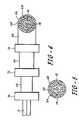
- a dielectric layer 64, a loadbearing layer 66 and/or a protective jacket 68 may be fabricated about the cable assembly.
- An apparatus for forming all three layers is illustrated in Figure 6.
- the dielectric layer 64 for situations where the tube 14 acts as an electrical conductor may be fabricated in any suitable manner using any suitable apparatus 70 known in the art.
- the dielectric layer 64 may be extruded about the tube 14 using an extrusion die. Although any suitable dielectric material may be used, it is preferred to fabricate the dielectric layer 64 from a high density polyethylene.
- the cable assembly 11 may be provided with a loadbearing layer 66.
- the loadbearing layer 66 may be formed from any suitable material such as polyethylene, a polyimide, an epoxy or other similar plastic material. If desired, the loadbearing layer 66 may comprise a contrahelix of plastic filaments in a thermosetting epoxy matrix. The fabrication of this layer may be done in any known manner using any suitable fabrication device 72, e.g., a die arrangement.
- the outer jacket 68 may be used in situations where abrasion resistance or additional protection is needed.
- the outer jacket 68 may be formed from any suitable material such as a protective plastic, rubber, nylon, neoprene, polyethylene, polyurethane or the like. Any suitable apparatus 74 such as an extrusion die may be used to form the outer jacket 68.
- the fabrication of the external layer or layers may be done off-line or in-line.
- the number of external layers to be fabricated depends upon the ultimate use for the optical fiber cable. For example, where the cable is to be deployed in an undersea environment, all three external layers may be used. For above-ground applications, only an outer jacket may be fabricated about the assembly 11.
- An optical fiber cable having an armor sheath formed from copper alloy C63800 was fabricated using a system similar to that shown in Figure 1.
- a single die was used to form the copper alloy C63800 tape into the armor sheath.
- the armor sheath had an outer diameter of about 0.036" (0.9 mm) and a wall thickness of about 0.007" (179 ⁇ m).
- a pull force of about 55 pounds (245 N) was used to pull the tape through the forming die.
- the light attenuation decreased from 43 db/km to 3.7 db.km with increasing back tension from 0.4 lbs to 1.6 lbs (1.8 to 7.1 N).
- the final light attenuation was the same as the starting light attenuation or no light loss was caused by processing.
- the optical fiber cable produced by the instant invention can be used in underground, aboveground and undersea communication applications.
- it could be used to supply data support and power to a deep sea sensor. It could also be used for underground, aboveground and undersea telephone applications.
- the intermediate tensioning device may be omitted.
- the take-up reel applies the pull force needed for tube formation.
- an accumulator to apply the back tension force to the fiber
- other means known in the art such as a dancer or a suspended weight could be used to apply the back tension force.
- an insertion needle not shown may be used to protect the fiber or fibers during armor tube formation.
- the use of an insertion needle is also recommended if a filler material such as a gel is to be inserted in the armor tube. Any suitable filler material known in the art may be used in the cable assemblies of the present invention.
- tube forming apparatus of Figure 3 illustrates the use of a die 30 for forming an open tube section
- forming rolls could be employed to form the open tube section.
- the final forming of the tube section into the tube should be by die forming as described herein.
- the tape 12 preferably comprises a flat continuous tape
- a preformed tape e.g., a tape having a preformed U-shaped cross-sectional configuration could also be used.
Landscapes
- Physics & Mathematics (AREA)
- General Physics & Mathematics (AREA)
- Optics & Photonics (AREA)
- Engineering & Computer Science (AREA)
- Manufacturing & Machinery (AREA)
- Optical Fibers, Optical Fiber Cores, And Optical Fiber Bundles (AREA)
- Insulated Conductors (AREA)
- Metal Extraction Processes (AREA)
- Surface Treatment Of Glass Fibres Or Filaments (AREA)
Applications Claiming Priority (2)
| Application Number | Priority Date | Filing Date | Title |
|---|---|---|---|
| US06/626,509 US4573253A (en) | 1984-06-29 | 1984-06-29 | Optical fiber cable fabrication technique |
| US626509 | 1984-06-29 |
Publications (2)
| Publication Number | Publication Date |
|---|---|
| EP0166621A2 true EP0166621A2 (fr) | 1986-01-02 |
| EP0166621A3 EP0166621A3 (fr) | 1988-03-02 |
Family
ID=24510667
Family Applications (1)
| Application Number | Title | Priority Date | Filing Date |
|---|---|---|---|
| EP85304621A Withdrawn EP0166621A3 (fr) | 1984-06-29 | 1985-06-28 | Technique de fabrication d'un câble à fibres optiques |
Country Status (4)
| Country | Link |
|---|---|
| US (1) | US4573253A (fr) |
| EP (1) | EP0166621A3 (fr) |
| JP (1) | JPS6117447A (fr) |
| KR (1) | KR860000568A (fr) |
Cited By (4)
| Publication number | Priority date | Publication date | Assignee | Title |
|---|---|---|---|---|
| EP0264622A1 (fr) * | 1986-10-15 | 1988-04-27 | Strabag Bau - Ag | Procédé de surveillance de la déformation de pièces au moyen de fibres optiques |
| US4830646A (en) * | 1986-11-18 | 1989-05-16 | Alcatel N.V. | Method and device for releasably fixing bare glass fibers in a splicing device |
| EP0440926A1 (fr) * | 1990-02-05 | 1991-08-14 | kabelmetal electro GmbH | Procédé de fabrication d'un élément de base pour cables de transmission d'informations à fibres optiques |
| EP0465656A4 (en) * | 1989-12-05 | 1992-06-03 | Nkk Corporation | Apparatus for and method of manufacturing optical fiber cable covered with metal pipe |
Families Citing this family (10)
| Publication number | Priority date | Publication date | Assignee | Title |
|---|---|---|---|---|
| US4790623A (en) * | 1983-05-24 | 1988-12-13 | Olin Corporation | Optical fiber cable assemblies |
| US4711388A (en) * | 1983-05-24 | 1987-12-08 | Olin Corporation | Process and apparatus for fabricating optical fiber cables |
| US4756595A (en) * | 1986-04-21 | 1988-07-12 | Honeywell Inc. | Optical fiber connector for high pressure environments |
| US4802730A (en) * | 1986-11-10 | 1989-02-07 | Olin Corporation | Optical fiber cables for motor vehicle engine compartment applications |
| US4759487A (en) * | 1987-03-09 | 1988-07-26 | K-Tube Corporation | Apparatus for continuous manufacture of armored optical fiber cable |
| US5106825A (en) * | 1987-07-31 | 1992-04-21 | Olin Corporation | Fabrication of superconducting wire and product |
| US4893895A (en) * | 1988-04-05 | 1990-01-16 | The Babcock & Wilcox Company | An improved encased high temperature optical fiber |
| EP1345057A3 (fr) * | 2002-03-16 | 2004-08-04 | Nexans | Méthode de fabrication pour un câble à fibres optiques |
| CN107240459A (zh) * | 2017-07-12 | 2017-10-10 | 中天电力光缆有限公司 | 一种光电复合缆及其制造方法 |
| CN115077411B (zh) * | 2022-07-05 | 2025-08-12 | 中核武汉核电运行技术股份有限公司 | 用于结构应变监测的一体化光电复合缆制造工艺及装备 |
Family Cites Families (14)
| Publication number | Priority date | Publication date | Assignee | Title |
|---|---|---|---|---|
| DE2449439C3 (de) * | 1974-10-15 | 1984-08-23 | Siemens AG, 1000 Berlin und 8000 München | Nachrichtenkabel mit Lichtleiter bzw. Lichtleiterbündel als Übertragungselemente |
| DE2507648A1 (de) * | 1975-02-19 | 1976-09-02 | Siemens Ag | Optisches kabel fuer nachrichtenuebertragungszwecke |
| DE2507649A1 (de) * | 1975-02-19 | 1976-09-02 | Siemens Ag | Optisches kabel fuer nachrichtenuebertragungszwecke |
| DE2743260C2 (de) * | 1977-09-26 | 1990-05-31 | kabelmetal electro GmbH, 3000 Hannover | Nachrichtenkabel mit Lichtwellenleitern und Verfahren zu seiner Herstellung |
| JPS54130037A (en) * | 1978-03-31 | 1979-10-09 | Kokusai Denshin Denwa Co Ltd | Optical fiber sea bottom cable and method of fabricating same |
| GB1583520A (en) * | 1978-05-12 | 1981-01-28 | Bicc Ltd | Optical cables |
| GB1592191A (en) * | 1978-05-30 | 1981-07-01 | Bicc Ltd | Optical cables |
| FR2444282A1 (fr) * | 1978-12-12 | 1980-07-11 | Cables De Lyon Geoffroy Delore | Cable sous-marin a fibres optiques pour telecommunications, et procede et dispositif pour sa fabrication |
| US4367917A (en) * | 1980-01-17 | 1983-01-11 | Gray Stanley J | Multiple sheath cable and method of manufacture |
| NL8000382A (nl) * | 1980-01-22 | 1981-08-17 | Philips Nv | Optisch geleidend element, werkwijze voor het vervaardigen daarvan, inrichting voor het vervaardigen van een dergelijk element en optische telecommunicatiekabel voorzien van een dergelijk element. |
| GB2091903B (en) * | 1981-01-27 | 1984-11-14 | Bicc Ltd | Optical fibre cable |
| US4372792A (en) * | 1981-10-15 | 1983-02-08 | Bicc Limited | Manufacture of a flexible stranded optical fiber body |
| JPS5895304A (ja) * | 1981-11-23 | 1983-06-06 | オリン・コ−ポレ−シヨン | 光フアイバ−通信ケ−ブルの組立て方法と装置 |
| US4446686A (en) * | 1982-09-02 | 1984-05-08 | At&T Technologies, Inc. | Methods of and apparatus for controlling core-to-sheath length ratio in lightguide fiber cable and cable produced by the methods |
-
1984
- 1984-06-29 US US06/626,509 patent/US4573253A/en not_active Expired - Fee Related
-
1985
- 1985-06-28 EP EP85304621A patent/EP0166621A3/fr not_active Withdrawn
- 1985-06-28 JP JP60141429A patent/JPS6117447A/ja active Pending
- 1985-06-29 KR KR1019850004660A patent/KR860000568A/ko not_active Withdrawn
Cited By (5)
| Publication number | Priority date | Publication date | Assignee | Title |
|---|---|---|---|---|
| EP0264622A1 (fr) * | 1986-10-15 | 1988-04-27 | Strabag Bau - Ag | Procédé de surveillance de la déformation de pièces au moyen de fibres optiques |
| US4830646A (en) * | 1986-11-18 | 1989-05-16 | Alcatel N.V. | Method and device for releasably fixing bare glass fibers in a splicing device |
| EP0465656A4 (en) * | 1989-12-05 | 1992-06-03 | Nkk Corporation | Apparatus for and method of manufacturing optical fiber cable covered with metal pipe |
| EP0440926A1 (fr) * | 1990-02-05 | 1991-08-14 | kabelmetal electro GmbH | Procédé de fabrication d'un élément de base pour cables de transmission d'informations à fibres optiques |
| AU640736B2 (en) * | 1990-02-05 | 1993-09-02 | Kabelmetal Electro Gmbh | Manufacturing of optical waveguide with a metallic sheath |
Also Published As
| Publication number | Publication date |
|---|---|
| JPS6117447A (ja) | 1986-01-25 |
| EP0166621A3 (fr) | 1988-03-02 |
| US4573253A (en) | 1986-03-04 |
| KR860000568A (ko) | 1986-01-29 |
Similar Documents
| Publication | Publication Date | Title |
|---|---|---|
| US4573253A (en) | Optical fiber cable fabrication technique | |
| US4730894A (en) | Optical fiber cable having a prefabricated strength system and methods of making | |
| US4446686A (en) | Methods of and apparatus for controlling core-to-sheath length ratio in lightguide fiber cable and cable produced by the methods | |
| US4089585A (en) | Optical guides | |
| US6529663B1 (en) | Self-supporting fiber optic cable having a support section with a non-uniform jacket | |
| US5448670A (en) | Elliptical aerial self-supporting fiber optic cable and associated apparatus and methods | |
| US5509097A (en) | Optical fiber core and cable with reinforced buffer tube loosely enclosing optical fibers | |
| US4710594A (en) | Telecommunications cable | |
| CA1221861A (fr) | Cable blinde enveloppant un tube hermetiquement scelle sur une fibre optique | |
| US6559385B1 (en) | Stranded cable and method of making | |
| US6744954B1 (en) | Submarine optical cable, optical fiber unit employed in the submarine optical cable, and method of making optical fiber unit | |
| CA2084911C (fr) | Methode servant a fabriquer un element de cable a fibres optiques | |
| CA2362522C (fr) | Procede de fabrication d'un systeme de cables metalliques conducteurs souterrains | |
| US4190319A (en) | Fiber optic ribbon and cable made therefrom | |
| GB2109950A (en) | Method and apparatus for assembling an optical fiber communication cable | |
| WO2006113322A1 (fr) | Méthode et système fournissant une barrière de diffusion d'hydrogène pour les câbles de fibre optique utilisés en environnements hostiles | |
| US4949894A (en) | Method and apparatus for forming ultra-small optical fiber cable assemblies | |
| CA2021971A1 (fr) | Systemes de transmissions electrique et optique a conducteurs aeriens | |
| CA1225208A (fr) | Fabrication d'une ame de cable a fibres optiques | |
| US4548664A (en) | Method of injecting a viscous filler material into fiber-receiving grooves in the core of an optical fiber cable | |
| US4711388A (en) | Process and apparatus for fabricating optical fiber cables | |
| US4832441A (en) | Optical fiber cable | |
| EP0193382A2 (fr) | Câbles à fibre optique étanche | |
| JPH02282210A (ja) | 海底電気通信用光ファイバケーブルコア | |
| GB2091903A (en) | Optical fibre cable |
Legal Events
| Date | Code | Title | Description |
|---|---|---|---|
| PUAI | Public reference made under article 153(3) epc to a published international application that has entered the european phase |
Free format text: ORIGINAL CODE: 0009012 |
|
| AK | Designated contracting states |
Designated state(s): DE FR GB IT NL SE |
|
| PUAL | Search report despatched |
Free format text: ORIGINAL CODE: 0009013 |
|
| AK | Designated contracting states |
Kind code of ref document: A3 Designated state(s): DE FR GB IT NL SE |
|
| 17P | Request for examination filed |
Effective date: 19880824 |
|
| STAA | Information on the status of an ep patent application or granted ep patent |
Free format text: STATUS: THE APPLICATION IS DEEMED TO BE WITHDRAWN |
|
| 18D | Application deemed to be withdrawn |
Effective date: 19910103 |
|
| RIN1 | Information on inventor provided before grant (corrected) |
Inventor name: SHAPIRO, EUGENE Inventor name: SMITH, WARREN F. Inventor name: WINTER, JOSEPH |