EP0166660A1 - Dispositif d'écriture pour machine à dessiner - Google Patents
Dispositif d'écriture pour machine à dessiner Download PDFInfo
- Publication number
- EP0166660A1 EP0166660A1 EP85401238A EP85401238A EP0166660A1 EP 0166660 A1 EP0166660 A1 EP 0166660A1 EP 85401238 A EP85401238 A EP 85401238A EP 85401238 A EP85401238 A EP 85401238A EP 0166660 A1 EP0166660 A1 EP 0166660A1
- Authority
- EP
- European Patent Office
- Prior art keywords
- writing
- writing member
- support
- head
- magazine
- Prior art date
- Legal status (The legal status is an assumption and is not a legal conclusion. Google has not performed a legal analysis and makes no representation as to the accuracy of the status listed.)
- Granted
Links
Images


Classifications
-
- B—PERFORMING OPERATIONS; TRANSPORTING
- B43—WRITING OR DRAWING IMPLEMENTS; BUREAU ACCESSORIES
- B43L—ARTICLES FOR WRITING OR DRAWING UPON; WRITING OR DRAWING AIDS; ACCESSORIES FOR WRITING OR DRAWING
- B43L13/00—Drawing instruments, or writing or drawing appliances or accessories not otherwise provided for
- B43L13/02—Draughting machines or drawing devices for keeping parallelism
- B43L13/022—Draughting machines or drawing devices for keeping parallelism automatic
- B43L13/024—Drawing heads therefor
-
- G—PHYSICS
- G01—MEASURING; TESTING
- G01D—MEASURING NOT SPECIALLY ADAPTED FOR A SPECIFIC VARIABLE; ARRANGEMENTS FOR MEASURING TWO OR MORE VARIABLES NOT COVERED IN A SINGLE OTHER SUBCLASS; TARIFF METERING APPARATUS; MEASURING OR TESTING NOT OTHERWISE PROVIDED FOR
- G01D15/00—Component parts of recorders for measuring arrangements not specially adapted for a specific variable
- G01D15/22—Chopper bars for bringing recording element into contact with recording surface
Definitions
- the present invention relates to a writing device for a drawing machine and more particularly to a writing head equipped with a writing member of the pencil, pen or similar type.
- the invention also relates to a writing device comprising such a writing head associated with a magazine carrying a writing member interchangeable on command with that of the writing head.
- Writing devices are known in which the writing head is movable in translation relative to a printing medium which is itself movable in a direction perpendicular to that of movement of the head. Changes of writing member can be made by bringing the writing head to one end of its travel, in the vicinity of a magazine or barrel comprising housings where several writing members are stored. Transfer means automatically carry out the transfer of a writing member from the writing head to a free housing in the magazine and, conversely, the transfer of a writing member from a housing of the magazine to the writing head. 'writing.
- the writing head generally comprises a support adapted to receive a writing member mounted movable in a longitudinal direction between a rest position (raised) and a working position (lowered) used to carry out the tracing.
- the object of the present invention is to provide a writing head with a very simple structure allowing a path that is both fast and precise.
- the object of the invention is more particularly to provide a writing head in which the mass to be displaced in order to move the writing member from its rest position to its working position, or vice versa, is minimal, while ensuring very precise guidance of the writing member when it is brought into the working position.
- the object of the invention is also to produce a writing head which is easily suitable for the automatic change of writing member.
- Another object of the present invention is to provide a writing device in which both the structure of the writing head and of the magazine and the transfer means are considerably simplified compared to existing devices.
- a writing head for a drawing machine comprises a support adapted to receive a writing member mounted movable in a longitudinal direction; means selectively controlled to move said writing member in the longitudinal direction between a rest position and a working position; guide means arranged on said support for receiving, in lateral support, the writing member in order to define the lateral position of said writing member while allowing its movement in the longitudinal direction relative to said support; and holding means for applying to said writing member a first magnetic attraction force in a lateral direction substantially perpendicular to the longitudinal direction in order to keep said writing member in lateral support on said guide means.
- the guide means are produced so as to minimize the friction between the writing member and the support in the longitudinal direction and are preferably constituted by rolling elements such as balls or rollers carried by the support and which roll. on the writing member when the latter is moved in the longitudinal direction.
- the guide means are arranged on a part of the support open laterally outward in a direction opposite to that of the magnetic attraction force applied to the writing member so that this writing member is separable from the support by traction exerted against said magnetic attraction force. An automatic change of the writing member is then possible by simply pulling the writing member in this opposite direction.
- a damping device is interposed between the support and the writing member to dampen the displacements of the writing member in the longitudinal direction, in particular to avoid bouncing of the tip of the writing member in position. of work.
- a writing device for a drawing machine comprises a writing head of the above type, a magazine adapted to carry a plurality of writing members and transfer means with command selective for transferring a writing member from the writing head to said magazine and from said magazine to the writing head.
- the magazine comprises a plurality of laterally accessible housings each comprising a bearing part against which a writing member can be brought, and magnetic attraction means for applying a second magnetic attraction force to each of the writing organs. lateral and thus maintain said writing members against said support portions of the respective housings.
- Said transfer means are adapted to temporarily modify at least one of the first and second magnetic attraction forces so that the result of said forces varies between a positive value capable of effecting a transfer of writing device from the head write to the magazine and a negative value capable of effecting a transfer of writing device from the magazine to the write head.
- said second magnetic attraction force applied by said magazine attraction means is a permanent magnetic force
- the first magnetic attraction force applied to said writing member by said writing head is variable, under l action of the transfer means, between a first and a second value respectively lower and greater than said second magnetic attraction force
- a preferred embodiment of the writing head comprises a permanent magnet to supply this first value of the first attraction force and an electromagnet supplied by the transfer means to supply, in combination with the permanent magnet, the second value of the first force of attraction.
- This electromagnet can also be used to move the writing member longitudinally between its rest position and its working position.
- the store preferably includes a permanent magnet associated with each housing.
- FIG. 1 very schematically shows a part of a drawing machine comprising, in a manner known per se, a writing head 1 mounted on a carriage 2 and a surface 3 for supporting and guiding a tracing support such as 'a sheet 11.
- the sheet 11 is moved longitudinally in a direction X by drive means by pins or by friction (not shown).
- the writing head is movable in translation in a horizontal transverse direction Y perpendicular to the direction X.
- the carriage 2 is secured to an endless ribbon or chain 4 which is driven by a motor 5. During its movement , the carriage 2 is guided by a slide 6.
- a rotary magazine 30 is mounted at one end of the stroke of the writing head, in order to be able to automatically change the writing member carried by the head.
- FIGS. 2A and 3 illustrate in more detail an embodiment of a writing head 1 forming part of a writing device according to the invention.
- This head 1 comprises a support 10 which carries a writing member 20.
- the latter (pencil, pen or the like), shown in phantom in Figure 2B, is mounted in a cylindrical body 21, the end of the member writing bearing the writing tip 24 projecting from the lower part of the body 21.
- the body 21 is made of non-magnetic material and carries a metal ring 22 made of magnetic material. At its upper part, above the ring 22, the body 21 has an annular shoulder or flange 23.
- the assembly formed by the writing member 20, the body 21, the ring 22 and the flange 23 is symmetrical of revolution around an axis 25.
- An electromagnet 16 comprising a coil 14 with an axis parallel to the body 21 and two armatures 15a, 15b is fixed to the support 10 for, when the coil 14 is supplied, bringing the writing member into the working position at the against the restoring force exerted by a magnet 12 described below.
- the end parts of the frames 15a, 15b are shaped to substantially match the contour of the ring 22, on a part of its periphery, on the same side of a plane P passing through the axis of the writing member.
- the reinforcements 15a, 15b are offset downwards relative to the ring 22 to attract the body 21 downwards with a substantially constant force.
- the bearing force of the tip 24 of the writing member on the sheet 11 is adjustable by displacement of the ring 22 longitudinally on the body 21 and / or by adjustment of the current supplying the coil 14.
- the body 21 is guided on the support 10 by means of two pairs of rollers 17, 18 mounted to rotate freely on the support 10 and located respectively above and below the electromagnet.
- the rollers are located on the side of the plane P where the reinforcements 15a, 15b are located and are arranged symmetrically with respect to one plane Q passing through the axis of the writing member and perpendicular to the plane P ( figure 3).
- the axes of the rollers 17, 18 are parallel to the plane Q and perpendicular to the axis 25 of the body 21, the latter being in contact with the slightly bevelled outer edges of the rollers 17, 18.
- rollers 17, 18 guide the body 21 in translation relative to the support 10, parallel to the axis 25, between a rest position, or raised ( Figure 2N in which the tip 24 overhangs the sheet 11 by a few mm and a position working, or lowered, in which the point 24 is supported on the sheet 11.
- the body 21 In the rest position, the body 21 is held in abutment against the rollers 17, 18 by means of a magnetic lateral holding force exerted on the ring 22 by the permanent magnet 12 fixed to the support 10 between the pairs of rollers 17 and 18.
- the magnet 12 is located at the level of the ring 22 and exerts a force substantially perpendicular to the axis 25.
- a pallet 26 is articulated at one end on the support 10 around an axis 19 perpendicular to the axis 25 and has at its other end a recess 26a in which the flange 23 of the body 21 engages with reduced play, l recess 26a having a flared opening.
- the pallet 26 is permanently urged upwards by a spring 27, one end of which bears on the support 10 and the other end of which is disposed in a housing 26b formed in the underside of the pallet 26.
- the upper position of the pallet 26 is defined by contact with an adjustable stop 13 mounted on the support 10, while the lower position of the pallet 26 is defined by contact of the latter with an abutment surface of the support 10.
- the spring 27 is a helical spring inside which is disposed a cylinder 28 of deformable material, for example a synthetic foam material.
- the support 10 and the elements described above secured to the support 10 are all located on the same side of the plane of symmetry P of the body 21. Also, the body 21 can be detached from the support 10 by traction exerted on the body. against the horizontal component of the force exerted by the magnet 12.
- the body 21 forms with the writing member 20 and the ring 22 an assembly having a symmetry of revolution capable of being joined in any position angular to the rollers 17, 18 whose arrangement does not exhibit symmetry of revolution.
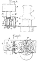
- the support 10 of the writing head opens laterally in the direction of the rotary magazine 30 which will now be described in detail with reference to FIGS. 2B, 4 and 5.
- the magazine 30 essentially comprises a support piece 31, or barrel, offering at its periphery a plurality of identical housings 32 for writing members.
- the barrel comprises a cylindrical body with a vertical axis A and two flanges 33, 34 located respectively at the upper part and at the lower part of the barrel and having at their periphery notches 35 in the form of arcs of a circle distributed regularly around the axis A.
- Two notches 35 aligned vertically define a housing 32 for the body of a writing member.
- the housings 32 are eight in number distributed regularly around the barrel.
- each notch 35 extends over an arc less than 180 ° so that the housings 32 are accessible radially.
- the body of the barrel 31 carries permanent magnets 36 in a number equal to that of the housings 32, each magnet being situated on the periphery of the barrel in the vicinity of the central part of a respective housing 32.
- a magnet 36 cooperates with the metal ring 22 of the body of a writing member to hold the latter in a housing 32, the body of the writing member being in lateral support against the cradles formed by the notches. 35 which define this accommodation.
- Figure 2B shows a dashed body of a writing member carried by the magazine 30.
- the magnet 36 is located at the ring 22 while the flange 23 of the body of the writing member is located above the upper flange 33 of the barrel 31.
- the magazine 30 carries a plurality of caps 37, each aligned vertically with a respective housing 32.
- the caps 37 are intended to protect the writing tips of the writing members stored on the barrel, and to close these tips to prevent drying of the ink.
- the barrel is integral at its lower part with an annular plate 38 provided with cells 39 aligned with the axes of the housings 32. Each cell is formed through the entire thickness of the plate 38.
- a plate 40 is fixed under the plate 38, this plate having orifices 41 of diameter smaller than those of the cells 39 and aligned with these.
- Each cap 37 is housed in a respective cell 39 and has a cylindrical lower part engaged through a corresponding orifice 41. At its upper part, the cap 37 has a horizontal rim 37a extended downwards by a vertical part 37b itself terminated by an external annular shoulder 37c.
- a spring 42 is mounted in the annular space with inverted U section which delimits the body of the cap and the flanges 37a, 37b.
- a metal piece 43 is fixed to the lower end of the cap.
- the cap 37 is movable vertically in the cell between a lower position (open cap) and an upper position (closed cap), being guided by the shoulder 37c against the side wall of the cell.
- the cap 37 When, the magazine having turned, the cap 37 is no longer subjected to the action of the magnet 45, this cap is recalled by the spring 42 in the closed position and bears against the body of a writing member in place in the corresponding housing 32. In the absence of a writing member, the upward movement of the cap 37 is limited by the coming of the shoulder 37c in abutment against an inner rim 39a surrounding the upper opening of the cell 39.
- a radial groove 44 is formed on the upper surface of the tray 38 between each cell 39 and the outer edge of the tray, in order to avoid damage to the writing tip when a writing member is placed on the store or extract thereof by lateral displacement.
- the body of the barrel 31 has a central passage 46 allowing the barrel to be mounted on a vertical rotary rod 50.
- the rod 50 carries, near its upper end, a finger or key 51 which engages in a corresponding radial housing 47 formed from an internal shoulder 48 of the passage 46 (see FIG. 2B).
- the finger 51 on the one hand, supports the barrel 31 on the rod 50 and, on the other hand, secures this rod and the barrel in rotation.
- the rod 50 is rotated by means of a motor 52, by means of reduction members housed in a casing 53. On its path between the reduction members and the barrel 31, the rod 50 is guided in a vertical bearing 54. The latter, as well as the motor 52 and the casing 53 are fixed on a plate 56. On the bearing 54 is fixed a lug 57 supporting the magnet 45.
- the plate 56 is movable between two positions. In the present embodiment, the axis of the barrel remains parallel to itself between these two extreme positions. As we can see on the Figures 4 and 5. the plate 56 is pivotally mounted about a vertical axis offset from the axis of the rotary magazine. For this purpose, the plate 56 is provided with a vertical bearing 58 crossed by a fixed axis 59 with interposition of rings 60, 61. The lower end of the axis 59 passes through the plate 56 and is threaded to receive a nut 62 which, by means of a washer 63, connects to the fixed axis 59 the plate 56 and all the elements which it supports.
- the height position of the magazine 30 is adjusted by screwing or unscrewing more or less the nut 62.
- a spring 64 is interposed between the bearing 58 and a shoulder of the axis 59 in order to contribute to maintaining the plate 56 in the position chosen.
- the axis 59 is integral with a part 65 of the machine carrying the guide slide of the writing head, the part 65 thus constituting the same reference for the positions of the writing head and the barrel .
- the pivoting of the plate 56 is limited by the coming into contact of a rod 66 fixed on the plate with stops carried by a part 67 fixed on the axis 59.
- the part 67 has a U-shaped end between the branches which is the rod 66.
- One of the branches has a threaded bore in which is screwed a screw 68 whose end defines a first adjustable position stop.
- the other branch, the furthest from the writing head, also has a threaded bore into which a hollow screw 69 is screwed, the end of which defines a second adjustable position stop.
- a spring 70 is housed in the screw 69 and exerts on the rod 66 a force tending to return the latter permanently against the stop 68 and, thereby, to return the barrel 31 in the direction of the writing head in a position where it intercepts the writing head to cooperate with it in the vicinity of the end of the stroke thereof.
- the writing member being in the rest position, it is brought to the working position by passing a current through the coil 14.
- the horizontal component of the electromagnetic force exerted by the electromagnet 16 is added to that of the force exerted by the magnet 12 to apply the body 21 against the rollers 17, 18.
- the body 21 is perfectly guided during its arrival in the working position and is then perfectly held in place in this position during the movements of the writing organ.
- the return of the writing member to the rest position is controlled by interrupting the current in the coil 14, the movement being ensured by the elastic return force exerted by the spring 27.
- the change of writing device is carried out automatically in the following manner.
- the support 10 of the writing member opens laterally in the direction of the magazine 30, that is to say that it is mounted on the carriage 2 (Fig. 1) so that the plane Q (Fig. 3) is parallel to the direction of movement of the head 1 and meets the barrel 31 at the end of the stroke thereof, the points of the frames 15a and 15b being oriented so as to present the writing member 20 opposite of the magazine 30 and the latter is movable in rotation so as to bring any of the housings 32 into a transfer position exactly facing the support 10.
- This transfer position corresponds to the location of the tab 57 which carries the magnet 45.
- the writing head carrying the writing member in the rest position is brought to the end of travel on the side of the magazine 30.
- the cap 37 of the housing 32 being in the open (lowered) position under the action of the magnet 45, the housing 32 is freely accessible laterally for the body of the writing member carried by the head.
- Each magnet 36 associated with a housing 32 is chosen so as to exert a magnetic attraction force greater than that exerted by the magnet 12 associated with the head. Also, as soon as the body of the writing member has reached the vicinity of the magnet 36 of the housing 32 in the transfer position, this magnet causes the writing member to be extracted from the head and the plate on the cradles 35.
- the height of the barrel 31 is adjusted so that the collar 23 of the body of the writing member comes to be placed just above the upper collar 33 of the barrel.
- the rest position of the plate 56 in abutment against the screw 68 is chosen so that the body of the writing member carried by the head comes into contact with the barrel 31, and even moves the plate 56 to the against spring 70, when the writing head reaches the end of its travel.
- the floating mounting of the barrel thus makes it possible to guarantee that the body of the writing member carried by the head at the end of the travel is always in contact with the cradles 35 of the housing 32 in the transfer position, even though the symmetry of the barrel in rotation would not be perfect.
- we guarantee that the body of the writing member carried by the head at the end of the race is always close enough to the magnet 36 so that the attractive force exerted by the latter can overcome that exerted by the magnet 12.
- the forces exerted by the magnet 12 on a writing member carried by the head and by a magnet 16 on a writing member located in the corresponding housing 32 can be respectively equal to 75 and 150 g.
- the barrel 31 is moved in rotation until the housing 32 containing the new chosen writing member is brought into the transfer position. It will be noted that the displacement of the barrel automatically causes the closure of the cap 37 associated with the writing member which has just been extracted from the head and the opening of the cap 37 associated with the new writing member chosen.
- the head is again brought into the end-of-travel position, against the body of the new writing member, the correct contact between the support 11 and this writing member being guaranteed by the floating mounting of the barrel.
- the coil 14 is then supplied.
- the horizontal component of the electromagnetic force exerted by the electromagnet 16 is added to the force exerted by the permanent magnet 12 to tear off the writing member from the housing 32 and press it against the rollers 17, 18.
- the head is moved back and the supply to the coil 14 is cut off before the flange 23 leaves contact with the flange 33 and when the distance of the writing member from the barrel is sufficient for the force exerted by the magnet 36 on the body of the writing member is less than that exerted by the permanent magnet 12.
- this distance can be chosen equal to approximately 2 or 3 mm, which requires to provide an overlap at least equal to the flanges 23 and 33.
- the horizontal attraction force exerted jointly by the magnet 12 and the electromagnet 16 can be about 250 g.
- the magnet 12 can be omitted from the assembly of FIG. 1 provided that a magnetized ring 22 is used.
- the lateral holding force (and possibly restoring to the rest position) is then constituted by the force of attraction between the magnetized ring and the armatures of the electromagnet under the correct polarity, a rapid rise of the organ d 'writing can be controlled by reversing the direction of the current in the coil.
- this transfer may be carried out by establishing an essentially horizontal electromagnetic force, independent of the means used to move the writing member into the working position.
- the present invention aims to cover all cases where the holding of the writing member on the head or in a magazine housing is ensured by a magnetic force and where the transfer from the head to a store housing, or conversely, is ensured by the difference between the magnetic forces exerted on the body of the writing member.
Landscapes
- Physics & Mathematics (AREA)
- General Physics & Mathematics (AREA)
- Engineering & Computer Science (AREA)
- Automation & Control Theory (AREA)
Abstract
Description
- La présente invention concerne un dispositif d'écriture pour machine à dessiner et plus particulièrement une tête d'écriture équipée d'un organe d'écriture du type crayon, stylo ou analogue. L'invention se rapporte également à un dispositif d'écriture comprenant une telle tête d'écriture associée à un magasin porteur d'organe d'écriture interchangeables sur commande avec celui de la tête d'écriture.
- On connaît des dispositifs d'écriture dans lesquels la tête d'écriture est mobile en translation par rapport à un support d'impression lui-même mobile dans une direction perpendiculaire à celle de déplacement de la tête. Des changements d'organe d'écriture peuvent être réalisés en amenant la tête d'écriture à une extrémité de sa course, au voisinage d'un magasin ou barillet comportant des logements où sont stockés plusieurs organes d'écriture. Des moyens de transfert réalisent automatiquement le transfert d'un organe d'écriture de la tête d'écriture à un logement libre du magasin et, inversement, le transfert d'un organe d'écriture d'un logement du magasin à la tête d'écriture.
- La tête d'écriture comprend généralement un support adapté à recevoir un organe d'écriture monté mobile dans une direction longitudinale entre une position de repos (relevée) et une position de travail (abaissée) utilisée pour effectuer le tracé.
- L'obtention de tracés rapides et précis au moyen de machines à dessiner demande, d'une part, des mouvements rapides de l'organe d'écriture entre ses positions de repos et de travail et, d'autre part, un guidage parfait de l'organe d'écriture au moins quand il vient en position abaissée.
- Il est connu d'utiliser des moyens électromagnétiques pour commander les déplacements de l'organe d'écriture entre ses positions relevée et abaissée. Afin de réduire au minimum la masse à mettre en mouvement au cours de ces déplacements, il a été proposé de réaliser des têtes d'écriture dans lesquelles seul l'organe d'écriture est déplacé. Un dispositif de ce type est décrit dans le brevet U.S. 4 299 031. Dans ce dispositif, le corps de l'organe d'écriture porte une pièce métallique qui coopère avec un aimant permanent et un électro-aimant pour, respectivement, relever et abaisser l'organe d'écriture. Le corps de l'organe d'écriture est guidé à l'intérieur d'une pièce tubulaire. Il est nécessaire que ce guidage soit réalisé avec un jeu minimum pour amener l'organe d'écriture en position de travail avec la précision souhaitée ; mais alors les frottements entre le corps de l'organe d'écriture et la pièce tubulaire peuvent être tels qu'il s'opposent aux mouvements de l'organe d'écriture entre ses positions relevée et abaissée et nuisent donc au bon fonctionnement de la tête.
- Dans le but d'assurer un guidage efficace sans rencontrer de problèmes de frottements, il est proposé par le brevet DE 3.217.755 de monter l'organe d'écriture sur un chariot dont les roues sont montées par rapport à des tiges de guidage de manière à interdire tout mouvement relatif entre l'organe d'écriture et ces tiges autrement que parallèlement à celles-ci. Le montage proposé est relativement complexe et l'on retrouve le problème posé par le déplacement d'une masse assez importante. De plus, et comme dans le cas précédent, le montage ne se prête pas facilement au changement automatique de l'organe d'écriture.
- La présente invention a pour objet de fournir une tête d'écriture de structure très simple autorisant un tracé à la fois rapide et précis.
- L'invention a plus particulièrement pour objet de fournir une tête d'écriture dans laquelle la masse à déplacer pour faire passer l'organe d'écriture de sa position de repos à sa position de travail, ou inversement, est minimale, tout en assurant un guidage très précis de l'organe d'écriture lorsqu'il est amené en position de travail.
- L'invention a encore pour objet de réaliser une tête d'écriture se prêtant facilement au changement automatique d'organe d'écriture.
- La présente invention a en outre pour but de fournir un dispositif d'écriture dans lequel tant la structure de la tête d'écriture et du magasin que les moyens de transfert sont considérablement simplifiés par rapport aux dispositifs existants.
- Selon un aspect de l'invention, une tête d'écriture pour machine à dessiner comprend un support adapté à recevoir un organe d'écriture monté mobile dans une direction longitudinale ; des moyens commandés sélectivement pour déplacer ledit organe d'écriture dans la direction longitudinale entre une position de repos et une position de travail ; des moyens de guidage disposés sur ledit support pour recevoir, en appui latéral, l'organe d'écriture afin de définir la position latérale dudit organe d'écriture tout en autorisant son déplacement dans la direction longitudinale par rapport audit support ; et des moyens de maintien pour appliquer audit organe d'écriture une première force d'attraction magnétique dans une direction latérale sensiblement perpendiculaire à la direction longitudinale afin de maintenir ledit organe d'écriture en appui latéral sur lesdits moyens de guidage.
- Les moyens de guidage sont réalisés de manière à minimiser les frottements entre l'organe d'écriture et le support dans la direction longitudinale et sont constitués de préférence par des éléments de roulement tels que des billes ou des galets portés par le support et qui roulent sur l'organe d'écriture lorsque celui-ci est déplacé dans la direction longitudinale.
- Selon une autre caractéristique de la tête d'écriture conforme à l'invention, les moyens de guidage sont disposés sur une partie du support ouverte latéralement vers l'extérieur dans une direction opposée à celle de la force d'attraction magnétique appliquée à l'organe d'écriture de façon que cet organe d'écriture soit séparable du support par traction exercée à l'encontre de ladite force d'attraction magnétique. Un changement automatique de l'organe d'écriture est alors possible par simple traction de l'organe d'écriture dans cette direction opposée.
- Avantageusement, un dispositif amortisseur est interposé entre le support et l'organe d'écriture pour amortir les déplacements de l'organe d'écriture dans la direction longitudinale, notamment pour éviter des rebondissements de la pointe de l'organe d'écriture en position de travail.
- Selon un autre aspect de l'invention, un dispositif d'écriture pour machine à dessiner comprend une tête d'écriture du type ci-dessus, un magasin adapté à porter une pluralité d'organes d'écriture et des moyens de transfert à commande sélective pour transférer un organe d'écriture de la tête d'écriture audit magasin et dudit magasin à la tête d'écriture. Le magasin comprend une pluralité de logements latéralement accessibles comportant chacun une partie d'appui contre laquelle peut être amené un organe d'écriture, et des moyens d'attraction magnétique pour appliquer à chacun des organes d'écriture une deuxième force d'attraction magnétique latérale et maintenir ainsi lesdits organes d'écriture contre lesdites parties d'appui des logements respectifs. Lesdits moyens de transfert sont adaptés à modifier temporairement l'une au moins des première et deuxième forces d'attraction magnétique de manière que la résultante desdites forces varie entre une valeur positive susceptible d'effectuer un transfert d'organe d'écriture depuis la tête d'écriture vers le magasin et une valeur négative susceptible d'effectuer un transfert d'organe d'écriture depuis le magasin vers la tête d'écriture.
- Avantageusement, ladite deuxième force d'attraction magnétique appliquée par lesdits moyens d'attraction du magasin est une force magnétique permanente, tandis que la première force d'attraction magnétique appliquée audit organe d'écriture par ladite tête d'écriture est variable, sous l'action des moyens de transfert, entre une première et une deuxième valeur respectivement inférieure et supérieure à ladite deuxième force d'attraction magnétique.
- Pour ce faire, un mode de réalisation préféré de la tête d'écriture comprend un aimant permanent pour fournir cette première valeur de la première force d'attraction et un électro-aimant alimenté par les moyens de transfert pour fournir, en combinaison avec l'aimant permanent, la deuxième valeur de la première force d'attraction. Cet électro-aimant peut être par ailleurs utilisé pour déplacer longitudinalement l'organe d'écriture entre sa position de repos et sa position de travail. Pour fournir la deuxième force d'attraction magnétique, le magasin comprend de préférence un aimant permanent associé à chaque logement.
- D'autres particularités et avantages du dispositif d'écriture conforme à l'invention ressortiront à la lecture de la description faite, ci-après, à titre indicatif mais non limitatif, en référence aux dessins annexés sur lesquels :
- - la figure 1 est une vue partielle d'une machine à dessiner munie d'un dispositif d'écriture selon l'invention,
- - les figures 2A et 2B sont des vues de face en élévation montrant respectivement une tête d'écriture et un magasin d'un dispositif d'écriture selon l'invention,
- - la figure 3 est une vue en coupe de la tête d'écriture suivant le plan III-III de la figure 2A,
- - la figure 4 est une vue en élévation de côté montrant le montage du magasin de la figure 2B, et
- - la figure 5 est une vue en coupe suivant le plan V-V de la figure 4.
- La figure 1 montre très schématiquement une partie d'une machine à dessiner comportant, de façon connue en soi, une tête d'écriture 1 montée sur un chariot 2 et une surface 3 de support et de guidage d'un support de tracé tel qu'une feuille 11.
- La feuille 11 est déplacé longitudinalement suivant une direction X par des moyens d'entraînement par picots ou par friction (non représentés). La tête d'écriture est mobile en translation dans une direction horizontale transversale Y perpendiculaire à la direction X. A cet effet, le chariot 2 est solidaire d'un ruban ou chaîne sans fin 4 qui est entraînée par un moteur 5. Pendant son déplacement, le chariot 2 est guidé par une glissière 6.
- Un magasin rotatif 30 est monté à une extrémité de la course de la tête d'écriture, afin de pouvoir changer automatiquement l'organe d'écriture porté par la tête.
- On se référera maintenant aux figures 2A et 3 qui illustrent plus en détail un mode de réalisation d'une tête d'écriture 1 faisant partie d'un dispositif d'écriture conforme à l'invention.
- Cette tête 1 comprend un support 10 qui porte un organe d'écriture 20. Ce dernier (crayon, stylo ou analogue), représenté en traits mixtes sur la figure 2B, est monté dans un corps cylindrique 21, l'extrémité de l'organe d'écriture portant la pointe d'écriture 24 faisant saillie à la partie inférieure du corps 21. Le corps 21 est en matériau non magnétique et porte une bague métallique 22 en matériau magnétique. A sa partie supérieure, au-dessus de la bague 22, le corps 21 présente un épaulement annulaire ou collerette 23. L'ensemble formé par l'organe d'écriture 20, le corps 21, la bague 22 et la collerette 23 est symétrique de révolution autour d'un axe 25.
- Un électro-aimant 16 comprenant une bobine 14 d'axe parallèle au corps 21 et deux armatures 15a, 15b est fixé au support 10 pour, lorsque la bobine 14 est alimentée, amener l'organe d'écriture en position de travail à l'encontre de la force de rappel exercée par un aimant 12 décrit plus loin. Les parties terminales des armatures 15a, 15b sont conformées pour épouser sensiblement le contour de la bague 22, sur une partie de sa périphérie, d'un même côté d'un plan P passant par l'axe de l'organe d'écriture. Les armatures 15a, 15b sont décalées vers le bas par rapport à la bague 22 pour attirer le corps 21 vers le bas avec une force sensiblement constante. La force d'appui de la pointe 24 de l'organe d'écriture sur la feuille 11 est réglable par déplacement de la bague 22 longitudinalement sur le corps 21 et/ou par ajustement du courant alimentant la bobine 14.
- Le corps 21 est guidé sur le support 10 au moyen de deux paires de galets 17, 18 montés libres en rotation sur le support 10 et situés respectivement au-dessus et au-dessous de l'électro-aimant.Dans chaque paire, les galets sont situés du côté du plan P où se trouvent les armatures 15a, 15b et sont disposés symétriquement l'un de l'autre par rapport à un plan Q passant par l'axe de l'organe d'écriture et perpendiculaire au plan P (figure 3).
- Comme le montre la figure 3, les axes des galets 17, 18 sont parallèles au plan Q et perpendiculaires à l'axe 25 du corps 21, celui-ci étant en contact avec les bords extérieurs légèrement biseautés des galets 17, 18.
- Les galets 17, 18 guident le corps 21 en translation par rapport au support 10, parallèlement à l'axe 25, entre une position de repos, ou relevée (figure 2N dans laquelle la pointe 24 surplombe la feuille 11 de quelques mm et une position de travail, ou abaissée, dans laquelle la pointe 24 est en appui sur la feuille 11.
- En position de repos, le corps 21 est maintenu en appui contre les galets 17, 18 au moyen d'une force magnétique de maintien latéral exercée sur la bague 22 par l'aimant permanent 12 fixé au support 10 entre les paires de galets 17 et 18. L'aimant 12 est situé au niveau de la bague 22 et exerce une force sensiblement perpendiculaire à l'axe 25.
- Une palette 26 est articulée à une extrémité sur le support 10 autour d'un axe 19 perpendiculaire à l'axe 25 et présente à son autre extrémité un évidement 26a dans lequel la collerette 23 du corps 21 s'engage avec un jeu réduit, l'évidement 26a ayant une ouverture évasée.
- La palette 26 est sollicitée en permanence vers le haut par un ressort 27 dont une extrémité prend appui sur le support 10 et dont l'autre extrémité est disposée dans un logement 26b formé dans la face inférieure de la palette 26. La position supérieure de la palette 26 est définie par le contact avec une butée ajustable 13 montée sur le support 10, tandis que la position inférieure de la palette 26 est définie par le contact de celle-ci avec une surface de butée du support 10.
- Le ressort 27 est un ressort hélicoidal à l'intérieur duquel est disposé un cylindre 28 de matériau déformable, par exemple un matériau en mousse synthétique.
- On notera que le support 10 et les éléments décrits ci-avant solidaires du support 10 sont situés tous d'un même côté du plan de symétrie P du corps 21. Aussi, le corps 21 peut être détaché du support 10 par traction exercée à l'encontre de la composante horizontale de la force exercée par l'aimant 12. Le corps 21 forme avec l'organe d'écriture 20 et la bague 22 un ensemble présentant une symétrie de révolution susceptible d'être accolé dans n'importe quelle position angulaire aux galets 17, 18 dont l'agencement ne présente pas de symétrie de révolution.
- On notera encore que le montage décrit permet d'utiliser sans adaptation particulière des organes d'écriture dont les corps ont des diamètres légèrement différents.
- Le support 10 de la tête d'écriture s'ouvre latéralement en direction du magasin rotatif 30 qui sera maintenant décrit en détail en référence aux figures 2B, 4 et 5.
- Le magasin 30 comprend essentiellement une pièce de support 31, ou barillet, offrant à sa périphérie une pluralité de logements identiques 32 pour des organes d'écriture.
- Le barillet comprend un corps cylindrique d'axe vertical A et deux collerettes 33, 34 situées respectivement à la partie supérieure et à la partie inférieure du barillet et présentant à leur périphérie des encoches 35 en forme d'arcs de cercle répartis régulièrement autour de l'axe A. Deux encoches 35 alignées verticalement définissent un logement 32 pour le corps d'un organe d'écriture. Dans l'exemple illustré, les logements 32 sont au nombre de huit répartis régulièrement autour du barillet.
- Comme le montre la figure 5, chaque encoche 35 s'étend sur un arc inférieur à 180° de sorte que les logements 32 sont accessibles radialement.
- Le corps du barillet 31 porte des aimants permanents 36 en nombre égal à celui des logements 32, chaque aimant étant situé à la périphérie du barillet au voisinage de la partie centrale d'un logement 32 respectif.
- Ainsi, un aimant 36 coopère avec la bague métallique 22 du corps d'un organe d'écriture pour maintenir celui-ci dans un logement 32, le corps de l'organe d'écriture étant en appui latéral contre les berceaux formés par les encoches 35 qui définissent ce logement.
- La figure 2Bmontre en tirets un corps d'organe d'écriture porté par le magasin 30. Comme on peut le voir sur cette figure, l'aimant 36 se trouve au niveau de la bague 22 tandis que la collerette 23 du corps de l'organe d'écriture est située au-dessus de la collerette supérieure 33 du barillet 31.
- A sa partie inférieure, le magasin 30 porte une pluralité de capuchons 37, chacun aligné verticalement avec un logement 32 respectif. Les capuchons 37 sont destinés à protéger les pointes d'écriture des organes d'écriture stockés sur le barillet, et à fermer ces pointes pour éviter le séchage de l'encre.
- Comme le montre la figure 2B le barillet est solidaire à sa partie inférieure d'un plateau annulaire 38 muni d'alvéoles 39 alignés avec les axes des logements 32. Chaque alvéole est formé à travers toute l'épaisseur du plateau 38. Une plaque 40 est fixée sous le plateau 38, cette plaque présentant des orifices 41 de diamètre inférieur à ceux des alvéoles 39 et alignés avec ceux-ci.
- Chaque capuchon 37, dont l'ouverture est tournée vers le haut, est logé dans un alvéole respectif 39 et a une partie inférieure cylindrique engagée à travers un orifice 41 correspondant. A sa partie supérieure, le capuchon 37 présente un rebord horizontal 37a prolongé vers le bas par une partie verticale 37b elle-même terminée par un épaulement annulaire extérieur 37c. Un ressort 42 est monté dans l'espace annulaire à section en U renversé que délimitent le corps du capuchon et les rebords 37a, 37b. Une pièce métallique 43 est fixée à l'extrémité inférieure du capuchon.
- Le capuchon 37 est mobile verticalement dans l'alvéole entre une position inférieure (capuchon ouvert) et une position supérieure (capuchon fermé), en étant guidé par l'épaulement 37c contre la paroi latérale de l'alvéole.
- Lorsque le magasin rotatif est amené dans une position angulaire telle qu'un capuchon 37 vient se placer au-dessus d'un aimant 45 non solidaire du magasin en rotation, cet aimant exerce sur la pièce métallique 43 une force d'attraction qui provoque le déplacement du capuchon vers le bas, à l'encontre de la force de rappel exercée par le ressort 42. La position inférieure du capuchon est définie par la venue de l'épaulement 37c en butée contre la plaque 40, autour de l'ouverture 41 (figure 2B).
- Lorsque, le magasin ayant tourné, le capuchon 37 n'est plus soumis à l'action de l'aimant 45, ce capuchon est rappelé par le ressort 42 en position de fermeture et vient s'appuyer contre le corps d'un organe d'écriture en place dans le logement 32 correspondant. En cas d'absence d'organe d'écriture, le déplacement vers le haut du capuchon 37 est limité par la venue de l'épaulement 37c en butée contre un rebord intérieur 39a entourant l'ouverture supérieure de l'alvéole 39.
- La venue du capuchon 37 en position inférieure autorise l'accès latéral au logement 32 correspondant. Une rainure radiale 44 est formée à la surface supérieure du plateau 38 entre chaque alvéole 39 et le bord extérieur du plateau, afin d'éviter l'endommagement de la pointe d'écriture lorsqu'un organe d'écriture est mis en place sur le magasin ou extrait de celui-ci par déplacement latéral.
- A l'exception des aimants 36 et des pièces métalliques 43, l'ensemble des éléments constitutifs du magasin 30 décrits plus haut est en matériau non magnétique, par exemple em matière plastique.
- Le corps du barillet 31 présente un passage central 46 permettant le montage du barillet sur une tige rotative verticale 50. La tige 50 porte au voisinage de son extrémité supérieure un doigt ou clavette 51 qui s'engage dans un logement radial correspondant 47 formé à partir d'un épaulement interne 48 du passage 46 (voir figure 2B).Le doigt 51, d'une part, supporte le barillet 31 sur la tige 50 et, d'autre part, solidarise cette tige et le barillet en rotation.
- La tige 50 est entraînée en rotation au moyen d'un moteur 52, par l'intermédiaire d'organes réducteurs logés dans un carter 53. Sur son trajet entre les organes réducteurs et le barillet 31, la tige 50 est guidée dans un palier vertical 54. Ce dernier, ainsi que le moteur 52 et le carter 53 sont fixés sur une platine 56. Sur le palier 54 est fixée une patte 57 supportant l'aimant 45.
- La platine 56 est déplaçable entre deux positions. Dans la présente réalisation, l'axe du barillet reste parallèle à lui-même entre ces deux positions extrêmes. Comme on peut le voir sur les figures 4 et 5. la platine 56 est montée pivotante autour d'un axe vertical décalé par rapport à l'axe du magasin rotatif. A cet effet, la platine 56 est munie d'un palier vertical 58 traversé par un axe fixe 59 avec interposition de bagues 60, 61. L'extrémité inférieure de l'axe 59 traverse la platine 56 et est filetée pour recevoir un écrou 62 qui, par l'intermédiaire d'une rondelle 63, relie à l'axe fixe 59 la platine 56 et tous les éléments qu'elle supporte.
- La position en hauteur du magasin 30 est réglée en vissant ou dévissant plus ou moins l'écrou 62. Un ressort 64 est interposé entre le palier 58 et un épaulement de l'axe 59 afin de contribuer au maintien de la platine 56 dans la position choisie. Avantageusement, l'axe 59 est solidaire d'une pièce 65 de la machine portant la glissière de guidage de la tête d'écriture, la pièce 65 constituant de la sorte une même référence pour les positions de la tête d'écriture et du barillet.
- Le pivotement de la platine 56 est limité par la venue en contact d'une tige 66 fixée sur la platine avec des butées portées par une pièce 67 fixée sur l'axe 59. La pièce 67 a une extrémité en forme de U entre les branches duquel se trouve la tige 66. Une des branches présente un alésage taraudé dans lequel est vissée une vis 68 dont l'extrémité définit une première butée de position ajustable. L'autre branche, la plus éloignée de la tête d'écriture, présente également un alésage taraudé dans lequel est vissée une vis creuse 69 dont l'extrémité définit une seconde butée de position ajustable. Un ressort 70 est logé dans la vis 69 et exerce sur la tige 66 une force tendant à rappeler celle-ci en permanence contre la butée 68 et, par là-même, à rappeler le barillet 31 dans la direction de la tête d'écriture dans une position où il intercepte la tête d'écriture pour coopérer avec celle-ci au voisinage de l'extrémité de la course de celle-ci.
- Le fonctionnement du dispositif d'écriture décrit ci-avant est le suivant.
- On considère d'abord uniquement le fonctionnement de la tête d'écriture.
- L'organe d'écriture étant en position de repos, il est amené vers la position de travail en faisant passer un courant dans la bobine 14. La composante horizontale de la force électromagnétique exercée par l'électro-aimant 16 s'ajoute à celle de la force exercée par l'aimant 12 pour appliquer le corps 21 contre les galets 17, 18. Ainsi, le corps 21 est parfaitement guidé pendant sa venue en position de travail et est ensuite parfaitement maintenu en place dans cette position pendant les déplacements de l'organe d'écriture.
- La venue de l'organe d'écriture en position de travail s'effectue à l'encontre de la force de rappel élastique exercée par le ressort 27. La présence de ce ressort et du bloc de matériau déformable 28 remplissant l'intérieur du ressort permet un amortissement des mouvements oscillatoires verticaux évitant, d'une part, les rebondissements de la pointe d'écriture lorsqu'elle est amenée en position de travail et, d'autre part, un décollement de la pointe d'écriture par rapport à la feuille 11 lorsque la pointe d'écriture rencontre des défauts de surface de la feuille 11 au cours du tracé.
- A titre indicatif, dans le cas où l'organe d'écriture est déplacé vers la position de travail sans interposition de moyens amortisseurs, il s'écoule environ 10 à 15 ms entre le moment où la pointe de l'organe d'écriture touche la feuille et le moment où cette pointe, après rebondissements, reste en contact permanent entre la feuille. L'interposition de moyens amortisseurs tels que décrits ci-dessus permet de ramener ce délai à 5 ms environ.
- Le retour de l'organe d'écriture en position de repos est commandé en interrompant le courant dans la bobine 14, le déplacement étant assuré par la force de rappel élastique exercée par le ressort 27.
- Le changement d'organe d'écriture est réalisé automatiquement de la façon suivante.
- Le support 10 de l'organe d'écriture s'ouvre latéralement dans la direction du magasin 30 c'est-à-dire qu'il est monté sur le chariot 2 (Fig. 1) de manière telle que le plan Q (Fig. 3) est parallèle à la direction de déplacement de la tête 1 et rencontre le barillet 31 à l'extrémité de la course de celle-ci, les pointes des armatures 15a et 15b étant orientées de manière à présenter l'organe d'écriture 20 vis à vis du magasin 30 et celui-ci est mobile en rotation de manière à amener l'un quelconque des logements 32 dans une position de transfert faisant face exactement au support 10. Cette position de transfert correspond à l'emplacement de la patte 57 qui porte l'aimant 45.
- Pour transférer un organe d'écriture porté par la tête d'écriture à un logement libre 32 situé en position de transfert, la tête d'écriture portant l'organe d'écriture en position de repos est amenée en fin de course du côté du magasin 30. Le capuchon 37 du logement 32 étant en position ouverte (abaissée) sous l'action de l'aimant 45, le logement 32 est librement accessible latéralement pour le corps de l'organe d'écriture porté par la tête. Chaque aimant 36 associé à un logement 32 est choisi de manière à exercer une force d'attraction magnétique supérieure à celle exercée par l'aimant 12 associé à la tête. Aussi, dès que le corps de l'organe d'écriture est parvenu au voisinage de l'aimant 36 du logement 32 en position de transfert, cet aimant provoque l'extraction de l'organe d'écriture de la tête et le plaque sur les berceaux 35.
- Le réglage en hauteur du barillet 31 est effectué afin que la collerette 23 du corps de l'organe d'écriture vienne se placer juste au-dessus de la collerette supérieure 33 du barillet.
- Par ailleurs, la position de repos de la platine 56 en butée contre la vis 68 est choisie de manière que le corps de l'organe d'écriture porté par la tête vienne en contact du barillet 31, et déplace même la platine 56 à l'encontre du ressort 70, lorsque la tête d'écriture parvient en fin de course. Le montage flottant du barillet permet ainsi de garantir que le corps de l'organe d'écriture porté par la tête en fin de course soit toujours au contact des berceaux 35 du logement 32 en position de transfert, quand bien même la symétrie du barillet en rotation ne serait pas parfaite. Par là-même, l'on garantit que le corps de l'organe d'écriture porté par la tête en fin de course est toujours suffisamment proche de l'aimant 36 pour que la force d'attraction exercée par celui-ci puisse vaincre celle exercée par l'aimant 12. A titre indicatif, les forces exercées par l'aimant 12 sur un organe d'écriture porté par la tête et par un aimant 16 sur un organe d'écriture situé dans le logement 32 correspondant peuvent être respectivemnt égales à 75 et 150 g.
- Pour transférer maintenant un nouvel organe d'écriture sur la tête, on procède comme suit.
- La tête étant reculée, le barillet 31 est déplacé en rotation jusqu'à amener en position de transfert le logement 32 contenant le nouvel organe d'écriture choisi. On notera que le déplacement du barillet entraîne automatiquement la fermeture du capuchon 37 associé à l'organe d'écriture qui vient d'être extrait de la tête et l'ouverture du capuchon 37 associé au nouvel organe d'écriture choisi.
- La tête est à nouveau amenée en position de fin de course, contre le corps du nouvel organe d'écriture, le contact correct entre le support 11 et cet organe d'écriture étant garanti par le montage flottant du barillet. La bobine 14 est alors alimentée. La composante horizontale de la force électromagnétique exercée par l'électroaimant 16 s'ajoute à la force exercée par l'aimant permanent 12 pour arracher l'organe d'écriture du logement 32 et le plaquer contre les galets 17, 18.
- L'abaissement de l'organe d'écriture sous l'action de la composante verticale de la force exercée par l'électroaimant est empêché par le contact de la collerette 23 avec la face supérieure de la collerette 33.
- La tête est reculée et l'alimentation de la bobine 14 est coupée avant que la collerette 23 quitte le contact avec la collerette 33 et lorsque l'éloignement de l'organe d'écriture par rapport au barillet est suffisant pour que la force exercée par l'aimant 36 sur le corps de l'organe d'écriture soit inférieure à celle exercée par l'aimant permanent 12. A titre indicatif, cet éloignement peut être choisi égal à environ 2 ou 3 mm, ce qui impose de prévoir un chevauchement au moins égal aux collerettes 23 et 33. Toujours à titre indicatif, la force d'attraction horizontale exercée conjointement par l'aimant 12 et l'électroaimant 16 peut être d'environ 250 g.
- En ce qui concerne le fonctionnement de la tête d'écriture, on a envisagé plus haut un rappel essentiellement élastique de l'organe d'écriture vers sa position de repos. Toutefois, ce rappel peut être en variante exercé au moins en partie par une force magnétique. A cet effet, il suffit de placer l'aimant 12 dans une position décalée vers le haut par rapport à la bague 22. La force d'attraction magnétique exercée par l'aimant 12 sur la bague 22 présente alors une composante horizontale faisant fonction de force de maintien latéral et une composante verticale faisant fonction de force de rappel en position de repos.
- Toujours à titre de variante, on peut supprimer l'aimant 12 du montage de la figure 1 à condition d'utiliser une bague 22 aimantée. La force de maintien latéral (et éventuellement de rappel en position de repos) est alors constituée par la force d'attraction entre la bague aimantée et les armatures de l'électro-aimant sous la polarité convenable, une remontée rapide de l'organe d'écriture pouvant être commandée en inversant le sens du courant dans la bobine.
- En ce qui concerne le changement d'organe d'écriture, on a envisagé plus haut l'utilisation pour le transfert du magasin à la tête d'écriture de la composante horizontale de la force électromagnétique utilisée pour commander la venue de l'organe d'écriture en position de travail. En variante, ce transfert pourra être effectué par établissement d'une force électromagnétique essentiellement horizontale, indépendante des moyens utilisés pour faire passer l'organe d'écriture en position de travail.
- D'une façon plus générale, la présente invention vise à recouvrir tous les cas où le maintien de l'organe d'écriture sur la tête ou dans un logement du magasin est assuré par une force magnétique et où le transfert de la tête à un logement du magasin, ou inversement, est assuré par la différence entre les forces magnétiques exercées sur le corps de l'organe d'écriture.
Claims (21)
Applications Claiming Priority (4)
| Application Number | Priority Date | Filing Date | Title |
|---|---|---|---|
| FR8409829A FR2566332B1 (fr) | 1984-06-22 | 1984-06-22 | Dispositif d'ecriture pour machine a dessiner |
| FR8409829 | 1984-06-22 | ||
| FR8416500A FR2572572B1 (fr) | 1984-10-29 | 1984-10-29 | Dispositif d'ecriture pour machine a dessiner |
| FR8416500 | 1984-10-29 |
Publications (2)
| Publication Number | Publication Date |
|---|---|
| EP0166660A1 true EP0166660A1 (fr) | 1986-01-02 |
| EP0166660B1 EP0166660B1 (fr) | 1990-10-03 |
Family
ID=26224027
Family Applications (1)
| Application Number | Title | Priority Date | Filing Date |
|---|---|---|---|
| EP85401238A Expired - Lifetime EP0166660B1 (fr) | 1984-06-22 | 1985-06-21 | Dispositif d'écriture pour machine à dessiner |
Country Status (4)
| Country | Link |
|---|---|
| US (1) | US4683476A (fr) |
| EP (1) | EP0166660B1 (fr) |
| CA (1) | CA1238619A (fr) |
| DE (1) | DE3579959D1 (fr) |
Cited By (1)
| Publication number | Priority date | Publication date | Assignee | Title |
|---|---|---|---|---|
| FR2604393A1 (fr) * | 1986-09-26 | 1988-04-01 | Rotring Werke Riepe Kg | Dispositif d'echange d'objets en particulier des stylets scripteurs |
Families Citing this family (19)
| Publication number | Priority date | Publication date | Assignee | Title |
|---|---|---|---|---|
| FR2623902B1 (fr) * | 1987-11-26 | 1990-05-04 | Schlumberger Ind Sa | Traceur ayant un plateau de support de feuille a profil angulaire |
| FR2624794B1 (fr) * | 1987-12-22 | 1990-06-08 | Schlumberger Ind Sa | Procede de changement d'outil d'ecriture dans une machine graphique et machine permettant la mise en oeuvre du procede |
| JPH0761759B2 (ja) * | 1988-02-05 | 1995-07-05 | 大日本スクリーン製造株式会社 | 自動製図機の描画具駆動装置 |
| JPH0785954B2 (ja) * | 1989-03-15 | 1995-09-20 | 武藤工業株式会社 | X―yプロッタにおける筆記芯自動供給装置 |
| US5212888A (en) * | 1991-09-16 | 1993-05-25 | Calcomp Inc. | Dual function sensor for a pen plotter |
| US6100911A (en) * | 1998-08-28 | 2000-08-08 | Eastman Kodak Company | Method and apparatus to provide a loading force print-head adjustment using magnets |
| DE10060815A1 (de) * | 2000-12-07 | 2002-06-20 | Henkel Kgaa | Steinverbundplatten |
| US6595998B2 (en) | 2001-03-08 | 2003-07-22 | Spinewave, Inc. | Tissue distraction device |
| US6997929B2 (en) * | 2003-05-16 | 2006-02-14 | Spine Wave, Inc. | Tissue distraction device |
| US7875078B2 (en) | 2004-08-25 | 2011-01-25 | Spine Wave, Inc. | Expandable interbody fusion device |
| US7967867B2 (en) * | 2007-05-31 | 2011-06-28 | Spine Wave, Inc. | Expandable interbody fusion device |
| US8715351B1 (en) | 2012-11-29 | 2014-05-06 | Spine Wave, Inc. | Expandable interbody fusion device with graft chambers |
| US8900312B2 (en) | 2013-03-12 | 2014-12-02 | Spine Wave, Inc. | Expandable interbody fusion device with graft chambers |
| US8828019B1 (en) | 2013-03-13 | 2014-09-09 | Spine Wave, Inc. | Inserter for expanding an expandable interbody fusion device |
| US9439783B2 (en) | 2014-03-06 | 2016-09-13 | Spine Wave, Inc. | Inserter for expanding body tissue |
| US11065132B2 (en) | 2014-03-06 | 2021-07-20 | Spine Wave, Inc. | Method of expanding a space between opposing tissue surfaces |
| US9078767B1 (en) | 2014-03-06 | 2015-07-14 | Spine Wave, Inc. | Expandable spinal interbody fusion device |
| US9445921B2 (en) | 2014-03-06 | 2016-09-20 | Spine Wave, Inc. | Device for expanding and supporting body tissue |
| US9265623B2 (en) | 2014-03-06 | 2016-02-23 | Spine Wave, Inc. | Method of expanding a spinal interbody fusion device |
Citations (3)
| Publication number | Priority date | Publication date | Assignee | Title |
|---|---|---|---|---|
| US2717820A (en) * | 1949-03-24 | 1955-09-13 | Foxboro Co | Industrial recording mechanism |
| DE2934273A1 (de) * | 1979-08-24 | 1981-03-12 | Aristo Graphic Systeme Gmbh & Co Kg, 2000 Hamburg | Vorrichtung zum bewegen der werkzeuge von automatischen zeichenmaschinen. |
| GB2082510A (en) * | 1980-09-01 | 1982-03-10 | Watanabe Instr | Automatic recording instrument |
Family Cites Families (9)
| Publication number | Priority date | Publication date | Assignee | Title |
|---|---|---|---|---|
| US2936207A (en) * | 1957-10-11 | 1960-05-10 | Vernon J Pick | Apparatus for displaying tri-dimensional data |
| US3543279A (en) * | 1969-07-22 | 1970-11-24 | Hewlett Packard Co | Point plotter for graphic recorder |
| NO131870C (fr) * | 1970-10-12 | 1975-08-20 | Kongsberg Vapenfab As | |
| US3883879A (en) * | 1973-08-28 | 1975-05-13 | Us Air Force | Portable pantograph c-scan recording flaw detecting system |
| DE2613440C3 (de) * | 1976-03-30 | 1981-12-03 | Rotring-Werke Riepe Kg, 2000 Hamburg | Automatische Zeichenvorrichtung |
| JPS582638Y2 (ja) * | 1976-05-27 | 1983-01-17 | セイコーインスツルメンツ株式会社 | ペンの支持装置 |
| GB1521086A (en) * | 1976-10-07 | 1978-08-09 | Flory H E | Electrically actuated marking apparatus |
| US4173021A (en) * | 1978-05-13 | 1979-10-30 | Koh-I-Noor Rapidograph, Inc. | Sealing element for an automatic drafting pen |
| GB1603558A (en) * | 1978-05-24 | 1981-11-25 | Metal Box Co Ltd | Plotting device |
-
1985
- 1985-06-13 US US06/744,353 patent/US4683476A/en not_active Expired - Fee Related
- 1985-06-21 DE DE8585401238T patent/DE3579959D1/de not_active Expired - Fee Related
- 1985-06-21 EP EP85401238A patent/EP0166660B1/fr not_active Expired - Lifetime
- 1985-06-21 CA CA000484735A patent/CA1238619A/fr not_active Expired
Patent Citations (3)
| Publication number | Priority date | Publication date | Assignee | Title |
|---|---|---|---|---|
| US2717820A (en) * | 1949-03-24 | 1955-09-13 | Foxboro Co | Industrial recording mechanism |
| DE2934273A1 (de) * | 1979-08-24 | 1981-03-12 | Aristo Graphic Systeme Gmbh & Co Kg, 2000 Hamburg | Vorrichtung zum bewegen der werkzeuge von automatischen zeichenmaschinen. |
| GB2082510A (en) * | 1980-09-01 | 1982-03-10 | Watanabe Instr | Automatic recording instrument |
Non-Patent Citations (2)
| Title |
|---|
| HEWLETT-PACKARD JOURNAL, vol. 32, no. 11, novembre 1981, pages 25-32, Amstelveen, NL; R.D. HASELBY et al.: "Y-axis pen handling system" * |
| HEWLETT-PACKARD JOURNAL, vol. 33, no. 12, décembre 1982, pages 28-33, Amstelveen, NL; R.M. KEMPLIN et al.: " Graphics plotter mechanical design for performance and reliability at low cost" * |
Cited By (1)
| Publication number | Priority date | Publication date | Assignee | Title |
|---|---|---|---|---|
| FR2604393A1 (fr) * | 1986-09-26 | 1988-04-01 | Rotring Werke Riepe Kg | Dispositif d'echange d'objets en particulier des stylets scripteurs |
Also Published As
| Publication number | Publication date |
|---|---|
| CA1238619A (fr) | 1988-06-28 |
| US4683476A (en) | 1987-07-28 |
| DE3579959D1 (de) | 1990-11-08 |
| EP0166660B1 (fr) | 1990-10-03 |
Similar Documents
| Publication | Publication Date | Title |
|---|---|---|
| EP0166660B1 (fr) | Dispositif d'écriture pour machine à dessiner | |
| CH701156B1 (fr) | Machine de rectifiage de bagues de roulements. | |
| FR2711125A1 (fr) | Chargeur pour machine d'impression pour objets présentés en pile. | |
| EP0541503B1 (fr) | Dispositif de transfert pour supports d'informations | |
| FR2472918A1 (fr) | Procede et dispositif d'alimentation continue de bande de papier d'une machine de traitement de tabac | |
| EP0541689B1 (fr) | Dispositif de positionnement a l'arret pour chariot de manutention | |
| FR2692071A1 (fr) | Tourne-disque. | |
| EP0023269B1 (fr) | Imprimante comportant une tête d'impression par points amovible | |
| EP1046517B1 (fr) | Machine de reproduction d'écriture | |
| EP3074198A1 (fr) | Dispositif de transport d'un corps creux comportant des moyens de préhension actionnés magnétiquement | |
| EP1401746B1 (fr) | Dispositif de transport de pieces pour l'alimentation de machines | |
| FR2572572A1 (fr) | Dispositif d'ecriture pour machine a dessiner | |
| CH644307A5 (fr) | Tete d'ecriture commutable. | |
| FR3096917A1 (fr) | Dispositif de préhension industriel | |
| EP0237690B1 (fr) | Tête d'écriture commutable | |
| EP0065172B1 (fr) | Machine à étiqueter portative | |
| EP0322307B1 (fr) | Procédé et dispositif pour le changement d'outil d'écriture dans une machine graphique | |
| CH647968A5 (en) | Rotary rest | |
| WO2016038274A1 (fr) | Dispositif a ressort | |
| EP0369859B1 (fr) | Dispositif pour l'entrainement sans jeu d'une bobine de cassette à bande magnétique. | |
| WO2003034330A1 (fr) | Dispositif de transport dans un systeme d'embossage de carte | |
| CH608411A5 (en) | Grinding machine | |
| FR2726806A1 (fr) | Procede et machine de vissage automatique de couvercles sur recipients arretes ou en mouvement | |
| EP0299312A2 (fr) | Accessoire pour machine imprimante, notamment pour machine à écrire de bureau | |
| CH509847A (fr) | Dispositif d'introduction d'une pièce de boîte de montre à usiner dans la pince d'une machine-outil |
Legal Events
| Date | Code | Title | Description |
|---|---|---|---|
| PUAI | Public reference made under article 153(3) epc to a published international application that has entered the european phase |
Free format text: ORIGINAL CODE: 0009012 |
|
| AK | Designated contracting states |
Designated state(s): BE CH DE FR GB IT LI SE |
|
| 17P | Request for examination filed |
Effective date: 19860424 |
|
| 17Q | First examination report despatched |
Effective date: 19871221 |
|
| RAP1 | Party data changed (applicant data changed or rights of an application transferred) |
Owner name: SCHLUMBERGER INDUSTRIES |
|
| RAP1 | Party data changed (applicant data changed or rights of an application transferred) |
Owner name: OCE GRAPHICS FRANCE S.A. |
|
| GRAA | (expected) grant |
Free format text: ORIGINAL CODE: 0009210 |
|
| AK | Designated contracting states |
Kind code of ref document: B1 Designated state(s): BE CH DE FR GB IT LI SE |
|
| REF | Corresponds to: |
Ref document number: 3579959 Country of ref document: DE Date of ref document: 19901108 |
|
| ITF | It: translation for a ep patent filed | ||
| GBT | Gb: translation of ep patent filed (gb section 77(6)(a)/1977) | ||
| PLBE | No opposition filed within time limit |
Free format text: ORIGINAL CODE: 0009261 |
|
| STAA | Information on the status of an ep patent application or granted ep patent |
Free format text: STATUS: NO OPPOSITION FILED WITHIN TIME LIMIT |
|
| 26N | No opposition filed | ||
| ITTA | It: last paid annual fee | ||
| EAL | Se: european patent in force in sweden |
Ref document number: 85401238.2 |
|
| PGFP | Annual fee paid to national office [announced via postgrant information from national office to epo] |
Ref country code: FR Payment date: 19950510 Year of fee payment: 11 |
|
| PGFP | Annual fee paid to national office [announced via postgrant information from national office to epo] |
Ref country code: GB Payment date: 19950512 Year of fee payment: 11 |
|
| PGFP | Annual fee paid to national office [announced via postgrant information from national office to epo] |
Ref country code: SE Payment date: 19950515 Year of fee payment: 11 |
|
| PGFP | Annual fee paid to national office [announced via postgrant information from national office to epo] |
Ref country code: CH Payment date: 19950526 Year of fee payment: 11 |
|
| PGFP | Annual fee paid to national office [announced via postgrant information from national office to epo] |
Ref country code: DE Payment date: 19950529 Year of fee payment: 11 |
|
| PGFP | Annual fee paid to national office [announced via postgrant information from national office to epo] |
Ref country code: BE Payment date: 19950530 Year of fee payment: 11 |
|
| PG25 | Lapsed in a contracting state [announced via postgrant information from national office to epo] |
Ref country code: GB Effective date: 19960621 |
|
| PG25 | Lapsed in a contracting state [announced via postgrant information from national office to epo] |
Ref country code: SE Effective date: 19960622 |
|
| PG25 | Lapsed in a contracting state [announced via postgrant information from national office to epo] |
Ref country code: LI Effective date: 19960630 Ref country code: CH Effective date: 19960630 Ref country code: BE Effective date: 19960630 |
|
| BERE | Be: lapsed |
Owner name: S.A. OCE GRAPHICS FRANCE Effective date: 19960630 |
|
| GBPC | Gb: european patent ceased through non-payment of renewal fee |
Effective date: 19960621 |
|
| REG | Reference to a national code |
Ref country code: CH Ref legal event code: PL |
|
| PG25 | Lapsed in a contracting state [announced via postgrant information from national office to epo] |
Ref country code: FR Effective date: 19970228 |
|
| PG25 | Lapsed in a contracting state [announced via postgrant information from national office to epo] |
Ref country code: DE Effective date: 19970301 |
|
| EUG | Se: european patent has lapsed |
Ref document number: 85401238.2 |
|
| REG | Reference to a national code |
Ref country code: FR Ref legal event code: ST |