EP0166699B1 - Dispositif pour détecter le passage par zéro d'un signal engendré par un détecteur électromagnétique utilisant un disque à cames se tournant à proximité d'un senseur - Google Patents
Dispositif pour détecter le passage par zéro d'un signal engendré par un détecteur électromagnétique utilisant un disque à cames se tournant à proximité d'un senseur Download PDFInfo
- Publication number
- EP0166699B1 EP0166699B1 EP85830125A EP85830125A EP0166699B1 EP 0166699 B1 EP0166699 B1 EP 0166699B1 EP 85830125 A EP85830125 A EP 85830125A EP 85830125 A EP85830125 A EP 85830125A EP 0166699 B1 EP0166699 B1 EP 0166699B1
- Authority
- EP
- European Patent Office
- Prior art keywords
- signal
- circuit
- comparator
- zero
- passage
- Prior art date
- Legal status (The legal status is an assumption and is not a legal conclusion. Google has not performed a legal analysis and makes no representation as to the accuracy of the status listed.)
- Expired
Links
- 230000000694 effects Effects 0.000 description 2
- 230000000630 rising effect Effects 0.000 description 2
- 238000010586 diagram Methods 0.000 description 1
- 238000000034 method Methods 0.000 description 1
Images

Classifications
-
- H—ELECTRICITY
- H03—ELECTRONIC CIRCUITRY
- H03K—PULSE TECHNIQUE
- H03K5/00—Manipulating of pulses not covered by one of the other main groups of this subclass
- H03K5/153—Arrangements in which a pulse is delivered at the instant when a predetermined characteristic of an input signal is present or at a fixed time interval after this instant
- H03K5/1536—Zero-crossing detectors
-
- G—PHYSICS
- G01—MEASURING; TESTING
- G01R—MEASURING ELECTRIC VARIABLES; MEASURING MAGNETIC VARIABLES
- G01R19/00—Arrangements for measuring currents or voltages or for indicating presence or sign thereof
- G01R19/175—Indicating the instants of passage of current or voltage through a given value, e.g. passage through zero
Definitions
- the present invention relates to a circuit for detecting the passage through zero of the signal generated by a variable-reluctance electromagnetic sensor of the phonic wheel type or the like.
- the invention concerns a detector circuit of the type comprising a first threshold comparator with hysteresis, for connection to the sensor and for outputting a signal indicative of the passage through zero of the signal at its input.
- a sensor or detector of the phonic wheel type is illustrated schematically in Figure 1. It comprises, in general, a disc W rotatable about its own axis and having a series of teeth N in suitable positions.
- a sensor S of electromagnetic type is associated with the disc W.
- the disc W may have notches instead of teeth.
- the phonic wheel sensor shown in Figure 1 has various applications, particularly in the field of motor vehicles, for example, for detecting the speed of rotation of the drive shaft or for detecting the moment at which the engine pistons pass
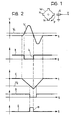
- the signal V is supplied to the input of a threshold comparator circuit with hysteresis, for outputting a signal of the type shown schematically by the waveform B in Figure 2:
- the threshold comparator is arranged so that its output changes state (for example, passing from a high to a low level) when the signal V exceeds a threshold level V, and changes state again when the signal V falls below zero.
- Each rising wave front b of the signal B is thus indicative of a passage of the signal V through zero, see for example Gal & Bibok, Nuclear Instruments and Methods 163 (1979) 535-539.
- the circuit for detecting the passage through zero of the signal V which has just been described has the disadvantage of being very sensitive to the effect of any disturbances picked up by the sensor S. Furthermore, if, for example, the disc W is not perfectly circular or is mounted slightly out of alignment, the signal output by the sensor may show spurious passages through zero.
- the object of the present invention is to provide a circuit for detecting the passage through zero of the signal generated by an electromagnetic sensor of the aforesaid type, which is reliable in operation even in the presence of disturbing pulses, and which is of fairly low cost.
- a detector circuit of the type specified at the beginning characterised in that it further includes:
- an electromagnetic sensor S is connected to a circuit 1 for detecting the passage through zero of the signal V generated by the sensor.
- the circuit 1 includes a threshold comparator 2 (of the type with hysteresis, for example inverting) with an input connected to the output of the sensor S, and the other input connected to a source 3 of a constant reference voltage V,.
- the output of the sensor S is also connected to an integrating circuit 4 of active type made, for example, with the use of an operational amplifier.
- the output of the integrator 4 is connected to a source 6 of a second threshold comparator 5 the other input of which is connected to a source 6 of a constant reference voltage V 2 .
- the outputs of the threshold comparators 2 and 5 are connected to respective inputs of a NOR circuit 7.
- the detector circuit described above operates in the following manner.
- the NOR circuit 7 outputs a signal having the waveform E of Figure 2: the descending front e of the signal E is thus indicative of the passage of the signal V through zero.
- the amplitude of the signal C output by the integrating circuit 4 is proportional to the energy associated with the signal V.
- the threshold comparator 5 and the NOR circuit 7 therefore cause the rising front b of the signal B to be interpreted as indicative of a passage of the signal V through zero only when the corresponding signal output by the sensor S has an energy greater than a minimum value.
Landscapes
- Physics & Mathematics (AREA)
- Nonlinear Science (AREA)
- General Physics & Mathematics (AREA)
- Arrangements For Transmission Of Measured Signals (AREA)
- Transmission And Conversion Of Sensor Element Output (AREA)
- Geophysics And Detection Of Objects (AREA)
- Measurement Of Current Or Voltage (AREA)
- Investigating Or Analyzing Materials By The Use Of Electric Means (AREA)
- Decoration By Transfer Pictures (AREA)
- Pinball Game Machines (AREA)
- Indication And Recording Devices For Special Purposes And Tariff Metering Devices (AREA)
Claims (3)
Priority Applications (1)
| Application Number | Priority Date | Filing Date | Title |
|---|---|---|---|
| AT85830125T ATE42003T1 (de) | 1984-05-31 | 1985-05-27 | Schaltung zur nulldurchgangsfeststellung eines, mittels eines elektromagnetischen fuehlers in form einer sich an einem sensor vorbeidrehenden nockenscheibe, erzeugten signals. |
Applications Claiming Priority (2)
| Application Number | Priority Date | Filing Date | Title |
|---|---|---|---|
| IT67560/84A IT1180067B (it) | 1984-05-31 | 1984-05-31 | Circuito rivelatore del passaggio per lo zero del segnale generato da un sensore elettromagnetico del tipo a ruota fonica e simili |
| IT6756084 | 1984-05-31 |
Publications (2)
| Publication Number | Publication Date |
|---|---|
| EP0166699A1 EP0166699A1 (fr) | 1986-01-02 |
| EP0166699B1 true EP0166699B1 (fr) | 1989-04-05 |
Family
ID=11303445
Family Applications (1)
| Application Number | Title | Priority Date | Filing Date |
|---|---|---|---|
| EP85830125A Expired EP0166699B1 (fr) | 1984-05-31 | 1985-05-27 | Dispositif pour détecter le passage par zéro d'un signal engendré par un détecteur électromagnétique utilisant un disque à cames se tournant à proximité d'un senseur |
Country Status (8)
| Country | Link |
|---|---|
| EP (1) | EP0166699B1 (fr) |
| JP (1) | JPS60262061A (fr) |
| AT (1) | ATE42003T1 (fr) |
| DE (1) | DE3569299D1 (fr) |
| ES (1) | ES8608174A1 (fr) |
| IT (1) | IT1180067B (fr) |
| PT (1) | PT80561B (fr) |
| YU (1) | YU45261B (fr) |
Families Citing this family (8)
| Publication number | Priority date | Publication date | Assignee | Title |
|---|---|---|---|---|
| IT1223867B (it) * | 1988-10-25 | 1990-09-29 | Marelli Autronica | Circuito per il trattamento del segnale generato da un sensore elettromagnetico di rotazione del tipo a riluttanza variabile |
| IT1223866B (it) * | 1988-10-25 | 1990-09-29 | Marelli Autronica | Circuito per il trattamento del segnale generato da un sensore elettromagnetico di rotazione a riluttanza variabile |
| IT1223943B (it) * | 1988-11-25 | 1990-09-29 | Marelli Autronica | Circuito per il trattamento del segnale generato da un sensore elettromagnetico di rotazione del tipo a riluttanza variabile |
| IT1238521B (it) * | 1989-11-07 | 1993-08-18 | Marelli Autronica | Circuito per il trattamento del segnale generato da un sensore elettromagnetico di rotazione a riluttanza variabile |
| US5001364A (en) * | 1989-12-11 | 1991-03-19 | Motorola, Inc. | Threshold crossing detector |
| GB2241335A (en) * | 1990-02-22 | 1991-08-28 | Ford Motor Co | Signal conditioning circuit |
| US9103847B2 (en) * | 2012-08-01 | 2015-08-11 | Freescale Semiconductor, Inc. | Variable reluctance sensor interface with integration based arming threshold |
| JP7173783B2 (ja) * | 2018-08-08 | 2022-11-16 | キヤノン株式会社 | ゼロクロス判別装置および画像形成装置 |
Family Cites Families (4)
| Publication number | Priority date | Publication date | Assignee | Title |
|---|---|---|---|---|
| US3768024A (en) * | 1972-09-25 | 1973-10-23 | Gen Motors Corp | Zero crossover detector circuit |
| DE2640242C2 (de) * | 1975-08-21 | 1985-06-27 | Siemens AG, 1000 Berlin und 8000 München | Schaltungsanordnung zum Erkennen der Nulldurchgänge von Signalen |
| ZA805412B (en) * | 1979-09-14 | 1981-08-26 | Plessey Overseas | Zero-crossing comparators with threshold validation |
| FR2541835B1 (fr) * | 1983-02-24 | 1988-10-07 | Peugeot | Montage d'exploitation de signaux electriques fournis par un capteur a reluctance variable |
-
1984
- 1984-05-31 IT IT67560/84A patent/IT1180067B/it active
-
1985
- 1985-05-27 AT AT85830125T patent/ATE42003T1/de not_active IP Right Cessation
- 1985-05-27 DE DE8585830125T patent/DE3569299D1/de not_active Expired
- 1985-05-27 EP EP85830125A patent/EP0166699B1/fr not_active Expired
- 1985-05-29 YU YU898/85A patent/YU45261B/xx unknown
- 1985-05-30 PT PT80561A patent/PT80561B/pt not_active IP Right Cessation
- 1985-05-30 ES ES543647A patent/ES8608174A1/es not_active Expired
- 1985-05-31 JP JP60116827A patent/JPS60262061A/ja active Pending
Also Published As
| Publication number | Publication date |
|---|---|
| YU89885A (en) | 1988-08-31 |
| ES543647A0 (es) | 1986-06-16 |
| IT8467560A1 (it) | 1985-12-01 |
| PT80561A (en) | 1985-06-01 |
| IT1180067B (it) | 1987-09-23 |
| PT80561B (pt) | 1987-05-06 |
| YU45261B (en) | 1992-05-28 |
| ES8608174A1 (es) | 1986-06-16 |
| ATE42003T1 (de) | 1989-04-15 |
| IT8467560A0 (it) | 1984-05-31 |
| JPS60262061A (ja) | 1985-12-25 |
| EP0166699A1 (fr) | 1986-01-02 |
| DE3569299D1 (en) | 1989-05-11 |
Similar Documents
| Publication | Publication Date | Title |
|---|---|---|
| US4764685A (en) | Method and circuit configuration for processing the output signals of a rotational speed sensor | |
| US5015878A (en) | Circuit for processing the signal generated by a variable-reluctance electromagnetic rotation sensor | |
| EP0602697B1 (fr) | Convertisseur analogique-numérique | |
| US5041769A (en) | DC motor apparatus with an index signal output | |
| US4028686A (en) | Digital detector | |
| EP0166699B1 (fr) | Dispositif pour détecter le passage par zéro d'un signal engendré par un détecteur électromagnétique utilisant un disque à cames se tournant à proximité d'un senseur | |
| JPS62161058A (ja) | モ−タの回転速度検出方法 | |
| US4039946A (en) | Tachometer | |
| JP2746699B2 (ja) | 信号処理回路 | |
| EP0149680A1 (fr) | Dispositif de detection de la vitesse d'un moteur electrique | |
| EP0350184A3 (fr) | Circuit détecteur d'interruption de train d'impulsions | |
| JPH0318759A (ja) | 輪速検出装置 | |
| SU1364918A1 (ru) | Устройство дл измерени механических параметров вращающегос вала | |
| JPS6416919A (en) | Rotational angle detector | |
| SU1497580A1 (ru) | Тахометрический преобразователь | |
| SU1365322A1 (ru) | Силовой след щий электропривод | |
| JPS5722525A (en) | Rotary body balancing device | |
| SU1432332A1 (ru) | Устройство дл измерени угла наклона | |
| JPS6370118A (ja) | 回転数検出回路 | |
| SU667803A1 (ru) | Устройство дл измерени перемещений с интерполированием | |
| SU1688141A1 (ru) | Прибор дл измерени момента трени подшипников качени | |
| RU1505283C (ru) | Устройство дл стабилизации заданной высоты полета | |
| SU1246314A1 (ru) | Электропривод посто нного тока | |
| JPS5736594A (en) | Power device for driving induction motor | |
| SU572706A1 (ru) | Устройство дл измерени колебаний скорости движени магнитного носител |
Legal Events
| Date | Code | Title | Description |
|---|---|---|---|
| PUAI | Public reference made under article 153(3) epc to a published international application that has entered the european phase |
Free format text: ORIGINAL CODE: 0009012 |
|
| AK | Designated contracting states |
Designated state(s): AT BE CH DE FR GB IT LI LU NL SE |
|
| 17P | Request for examination filed |
Effective date: 19860628 |
|
| 17Q | First examination report despatched |
Effective date: 19880513 |
|
| RAP1 | Party data changed (applicant data changed or rights of an application transferred) |
Owner name: MARELLI AUTRONICA S.P.A. |
|
| GRAA | (expected) grant |
Free format text: ORIGINAL CODE: 0009210 |
|
| AK | Designated contracting states |
Kind code of ref document: B1 Designated state(s): AT BE CH DE FR GB IT LI LU NL SE |
|
| REF | Corresponds to: |
Ref document number: 42003 Country of ref document: AT Date of ref document: 19890415 Kind code of ref document: T |
|
| ITF | It: translation for a ep patent filed | ||
| REF | Corresponds to: |
Ref document number: 3569299 Country of ref document: DE Date of ref document: 19890511 |
|
| ET | Fr: translation filed | ||
| PLBE | No opposition filed within time limit |
Free format text: ORIGINAL CODE: 0009261 |
|
| STAA | Information on the status of an ep patent application or granted ep patent |
Free format text: STATUS: NO OPPOSITION FILED WITHIN TIME LIMIT |
|
| 26N | No opposition filed | ||
| ITTA | It: last paid annual fee | ||
| PGFP | Annual fee paid to national office [announced via postgrant information from national office to epo] |
Ref country code: AT Payment date: 19940614 Year of fee payment: 10 |
|
| PGFP | Annual fee paid to national office [announced via postgrant information from national office to epo] |
Ref country code: BE Payment date: 19940620 Year of fee payment: 10 |
|
| PGFP | Annual fee paid to national office [announced via postgrant information from national office to epo] |
Ref country code: CH Payment date: 19940627 Year of fee payment: 10 |
|
| PGFP | Annual fee paid to national office [announced via postgrant information from national office to epo] |
Ref country code: LU Payment date: 19940630 Year of fee payment: 10 |
|
| EPTA | Lu: last paid annual fee | ||
| EAL | Se: european patent in force in sweden |
Ref document number: 85830125.2 |
|
| PG25 | Lapsed in a contracting state [announced via postgrant information from national office to epo] |
Ref country code: LU Free format text: LAPSE BECAUSE OF NON-PAYMENT OF DUE FEES Effective date: 19950527 Ref country code: AT Effective date: 19950527 |
|
| PG25 | Lapsed in a contracting state [announced via postgrant information from national office to epo] |
Ref country code: LI Effective date: 19950531 Ref country code: CH Effective date: 19950531 Ref country code: BE Effective date: 19950531 |
|
| BERE | Be: lapsed |
Owner name: MARELLI AUTRONICA S.P.A. Effective date: 19950531 |
|
| REG | Reference to a national code |
Ref country code: CH Ref legal event code: PL |
|
| PGFP | Annual fee paid to national office [announced via postgrant information from national office to epo] |
Ref country code: NL Payment date: 19980430 Year of fee payment: 14 |
|
| PGFP | Annual fee paid to national office [announced via postgrant information from national office to epo] |
Ref country code: SE Payment date: 19990329 Year of fee payment: 15 |
|
| PGFP | Annual fee paid to national office [announced via postgrant information from national office to epo] |
Ref country code: GB Payment date: 19990420 Year of fee payment: 15 |
|
| PGFP | Annual fee paid to national office [announced via postgrant information from national office to epo] |
Ref country code: DE Payment date: 19990426 Year of fee payment: 15 |
|
| PGFP | Annual fee paid to national office [announced via postgrant information from national office to epo] |
Ref country code: FR Payment date: 19990528 Year of fee payment: 15 |
|
| PG25 | Lapsed in a contracting state [announced via postgrant information from national office to epo] |
Ref country code: NL Free format text: LAPSE BECAUSE OF NON-PAYMENT OF DUE FEES Effective date: 19991201 |
|
| NLV4 | Nl: lapsed or anulled due to non-payment of the annual fee |
Effective date: 19991201 |
|
| PG25 | Lapsed in a contracting state [announced via postgrant information from national office to epo] |
Ref country code: GB Free format text: LAPSE BECAUSE OF NON-PAYMENT OF DUE FEES Effective date: 20000527 |
|
| PG25 | Lapsed in a contracting state [announced via postgrant information from national office to epo] |
Ref country code: SE Free format text: LAPSE BECAUSE OF NON-PAYMENT OF DUE FEES Effective date: 20000528 |
|
| GBPC | Gb: european patent ceased through non-payment of renewal fee |
Effective date: 20000527 |
|
| EUG | Se: european patent has lapsed |
Ref document number: 85830125.2 |
|
| PG25 | Lapsed in a contracting state [announced via postgrant information from national office to epo] |
Ref country code: FR Free format text: LAPSE BECAUSE OF NON-PAYMENT OF DUE FEES Effective date: 20010131 |
|
| REG | Reference to a national code |
Ref country code: FR Ref legal event code: ST |
|
| PG25 | Lapsed in a contracting state [announced via postgrant information from national office to epo] |
Ref country code: DE Free format text: LAPSE BECAUSE OF NON-PAYMENT OF DUE FEES Effective date: 20010403 |