EP0166788A1 - Einspritzmechanismus für spritzgiessmaschine - Google Patents
Einspritzmechanismus für spritzgiessmaschine Download PDFInfo
- Publication number
- EP0166788A1 EP0166788A1 EP85900199A EP85900199A EP0166788A1 EP 0166788 A1 EP0166788 A1 EP 0166788A1 EP 85900199 A EP85900199 A EP 85900199A EP 85900199 A EP85900199 A EP 85900199A EP 0166788 A1 EP0166788 A1 EP 0166788A1
- Authority
- EP
- European Patent Office
- Prior art keywords
- clutch
- injection
- motor
- screw
- energy
- Prior art date
- Legal status (The legal status is an assumption and is not a legal conclusion. Google has not performed a legal analysis and makes no representation as to the accuracy of the status listed.)
- Granted
Links
Images

Classifications
-
- B—PERFORMING OPERATIONS; TRANSPORTING
- B29—WORKING OF PLASTICS; WORKING OF SUBSTANCES IN A PLASTIC STATE IN GENERAL
- B29C—SHAPING OR JOINING OF PLASTICS; SHAPING OF MATERIAL IN A PLASTIC STATE, NOT OTHERWISE PROVIDED FOR; AFTER-TREATMENT OF THE SHAPED PRODUCTS, e.g. REPAIRING
- B29C45/00—Injection moulding, i.e. forcing the required volume of moulding material through a nozzle into a closed mould; Apparatus therefor
- B29C45/17—Component parts, details or accessories; Auxiliary operations
- B29C45/46—Means for plasticising or homogenising the moulding material or forcing it into the mould
- B29C45/47—Means for plasticising or homogenising the moulding material or forcing it into the mould using screws
- B29C45/50—Axially movable screw
- B29C45/5008—Drive means therefor
-
- B—PERFORMING OPERATIONS; TRANSPORTING
- B29—WORKING OF PLASTICS; WORKING OF SUBSTANCES IN A PLASTIC STATE IN GENERAL
- B29C—SHAPING OR JOINING OF PLASTICS; SHAPING OF MATERIAL IN A PLASTIC STATE, NOT OTHERWISE PROVIDED FOR; AFTER-TREATMENT OF THE SHAPED PRODUCTS, e.g. REPAIRING
- B29C45/00—Injection moulding, i.e. forcing the required volume of moulding material through a nozzle into a closed mould; Apparatus therefor
- B29C45/17—Component parts, details or accessories; Auxiliary operations
- B29C2045/1784—Component parts, details or accessories not otherwise provided for; Auxiliary operations not otherwise provided for
- B29C2045/1792—Machine parts driven by an electric motor, e.g. electric servomotor
-
- B—PERFORMING OPERATIONS; TRANSPORTING
- B29—WORKING OF PLASTICS; WORKING OF SUBSTANCES IN A PLASTIC STATE IN GENERAL
- B29C—SHAPING OR JOINING OF PLASTICS; SHAPING OF MATERIAL IN A PLASTIC STATE, NOT OTHERWISE PROVIDED FOR; AFTER-TREATMENT OF THE SHAPED PRODUCTS, e.g. REPAIRING
- B29C45/00—Injection moulding, i.e. forcing the required volume of moulding material through a nozzle into a closed mould; Apparatus therefor
- B29C45/17—Component parts, details or accessories; Auxiliary operations
- B29C45/46—Means for plasticising or homogenising the moulding material or forcing it into the mould
- B29C45/47—Means for plasticising or homogenising the moulding material or forcing it into the mould using screws
- B29C45/50—Axially movable screw
- B29C45/5008—Drive means therefor
- B29C2045/5076—Drive means therefor using a single drive motor for rotary and for axial movements of the screw
-
- B—PERFORMING OPERATIONS; TRANSPORTING
- B29—WORKING OF PLASTICS; WORKING OF SUBSTANCES IN A PLASTIC STATE IN GENERAL
- B29C—SHAPING OR JOINING OF PLASTICS; SHAPING OF MATERIAL IN A PLASTIC STATE, NOT OTHERWISE PROVIDED FOR; AFTER-TREATMENT OF THE SHAPED PRODUCTS, e.g. REPAIRING
- B29C45/00—Injection moulding, i.e. forcing the required volume of moulding material through a nozzle into a closed mould; Apparatus therefor
- B29C45/17—Component parts, details or accessories; Auxiliary operations
- B29C45/76—Measuring, controlling or regulating
- B29C45/7666—Measuring, controlling or regulating of power or energy, e.g. integral function of force
- B29C2045/7673—Recovering energy or power from drive motors
-
- Y—GENERAL TAGGING OF NEW TECHNOLOGICAL DEVELOPMENTS; GENERAL TAGGING OF CROSS-SECTIONAL TECHNOLOGIES SPANNING OVER SEVERAL SECTIONS OF THE IPC; TECHNICAL SUBJECTS COVERED BY FORMER USPC CROSS-REFERENCE ART COLLECTIONS [XRACs] AND DIGESTS
- Y02—TECHNOLOGIES OR APPLICATIONS FOR MITIGATION OR ADAPTATION AGAINST CLIMATE CHANGE
- Y02P—CLIMATE CHANGE MITIGATION TECHNOLOGIES IN THE PRODUCTION OR PROCESSING OF GOODS
- Y02P70/00—Climate change mitigation technologies in the production process for final industrial or consumer products
- Y02P70/10—Greenhouse gas [GHG] capture, material saving, heat recovery or other energy efficient measures, e.g. motor control, characterised by manufacturing processes, e.g. for rolling metal or metal working
Definitions
- the present invention relates to an injection mechanism for moving a screw in an axial direction to inject a molding material in an injection molding apparatus.
- a hydraulic or electric motor is used in a conventional injection mechanism for moving a screw in an axial direction to inject a molten molding material during injection. For this reason, the horse power and size of a motor must be increased in order to perform high-pressure, high-speed injection. However, when the motor size is increased, the injection molding apparatus becomes expensive as a whole. Furthermore, the rotor size of the motor must be increased to prolong the response time due to inertia influence, resulting in inconvenience.
- an injection mechanism in an injection molding apparatus for performing injection by moving a screw forward through a power transmission device for converting rotational movement to linear movement, wherein a rotating shaft of the motor is coupled to the power transmission device through a first clutch and to an energy accumulation device through a second clutch, so that, during an operation excluding injection and metering, the second clutch is operated to couple the energy accumulation device with the motor to cause the energy accumulation device to accumulate energy, and so that, during injection, a driving force of the motor is superposed on energy accumulated in the energy accumulation device to drive the screw so as to perform high-pressure, high-speed injection.
- energy generated by rotation of the motor during an idle time excluding injection and metering times is accumulated in the energy accumulation device.
- the accumulated energy in the energy accumulation device is added to the motor energy. Therefore, high-pressure, high-speed injection can be performed at a high response speed without increasing the motor power.
- the motor size need not be increased, and a compact motor can be used, thus providing an economical advantage.
- Fig. 1 is a schematic view showing an injection mechanism according to a first embodiment of the present invention
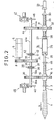
- Fig. 2 is a schematic view showing an injection mechanism according to a second embodiment of the present invention. Best Mode of Carrying Out the Invention
- Fig. 1 shows a first embodiment of the present invention.
- Reference numeral 1 denotes a screw mounted at a distal end of a screw shaft 2.
- a ball screw 4 as a male screw is coaxially mounted on the other end of the screw shaft 2 through a coupler 3 such as a flange.
- Reference numeral 5 denotes a servo motor.
- a sensor 6 is arranged on the servo motor 5 for position detection.
- a drive gear 8 is mounted at the distal end of a motor shaft 7.
- a transmission gear 9 is meshed with the drive gear 8.
- the transmission gear 9 is mounted on a transmission shaft 13 and is coupled to a transmission gear 14 mounted on a transmission shaft 14a through a clutch 12 having clutch plates 10 and 11.
- the transmission gear 9 is meshed with a transmission gear 16 integral with a nut 15 meshed with the ball screw 4.
- Reference numeral 17 denotes an energy accumulation device.
- the energy accumulation device 17 comprises a flywheel.
- the flywheel 17 is mounted on a wheel shaft 18 and is coupled to a transmission gear 23 mounted on a rotating shaft 22 through a clutch 21 having clutch plates 19 and 20.
- the transmission gear 23 is meshed with the drive gear 8.
- the clutch 21 is turned on and the servo motor 5 is operated in the noninjection/nonmetering mode, the drive gear 8 mounted at the distal end of the motor shaft 7 is rotated, so that a rotational force is transmitted to the transmission gear 23 meshed with the drive gear 8.
- the flywheel 17 is rotated through the clutch 21 having the coupled clutch plates 19 and 20.
- the clutch 21 is turned off and the servo motor 5 is stopped until an injection signal is generated.
- the clutches 12 and 21 are simultaneously turned on, the clutch plates 10 and 11 and the clutch plates 19 and 20 are coupled to each other, and at the same time the servo motor 5 is operated.
- the drive gear 8 is rotated at a high speed upon rotation of the servo motor 5 in coordination with the rotational force of the flywheel 17.
- the transmission gear 14 together with the transmission gear 9 is rotated at a high speed.
- the operation gear 16 meshed with the transmission gear 14 is rotated counterclockwise at a high speed. Therefore, the nut 15 integral with the operation gear 16 is rotated counterclockwise at a high speed.
- the ball screw 4 threadably engaged with the nut 15 is moved to the left in Fig. 1, and the screw 1 is also moved together with the ball screw to the left in Fig. 1, thereby injecting a molten molding material at a high pressure and a high speed. Injection control is performed by the sensor 6 mounted on the servo motor 5.
- the clutch 12 is turned on to couple the clutch plates 10 and 11 to each other.
- the clutch 21 is turned off. Every time a drag generated by the molten molding material upon rotation of the screw 1 reaches a predetermined pressure, the servo motor 5 is rotated in the reverse direction. The screw 1 is moved backward to a predetermined position while a back pressure is kept constant.
- the clutch 12 is turned off and at the same time the clutch 21 is turned on.
- the servo motor 5 is rotated in the forward direction, and energy is accumulated in the flywheel 17. The same operation as described above is repeatedly performed.
- the flywheel 17 and the clutch 21 are coupled to the transmission gear 23 meshed with the drive gear 8 driven by the servo motor 5.
- the transmission gear 23 need not be arranged.
- the clutch 21 may be coupled to the transmission gear 9 through the clutch 12 of the transmission shaft 13, so that the clutch 21 can be coupled to the flywheel 17.
- the clutch 12 is turned off and the clutch 21 is operated.
- the rotational force of the servo motor 5 is transmitted to the flywheel 17 through the drive gear 8, the transmission gear 9 and the clutch 21, thereby accumulating energy.
- the clutches 12 and,21 are simultaneously operated.
- Fig. 2 shows a second embodiment of the present invention.
- An energy accumulation device comprises a gas accumulator.
- a screw shaft 2 is mounted integrally with one end of a screw 1.
- a ball screw 4 is mounted coaxially with the rear end of the screw shaft 2 through a coupler 3 such as a flange.
- a piston rod 25 of a gas accumulator 24 is coupled to one end of the ball screw 4 through a coupler 48.
- a shaft 27 is coupled to one end of a cylinder 26 of the gas accumulator 24 filled with a high-pressure gas.
- a ball screw 29 is mounted to the distal end of the shaft 27 through a coupler 28.
- An abutment plate 30 is mounted on the distal end of the ball screw 29.
- An operation gear 16 having a nut 15 meshed with the ball screw 4 is mounted thereon.
- An operation gear 32 having a nut 31 meshed with the ball screw 29 is mounted thereon.
- Reference numeral 33 denotes a shock absorber for damping an impact of the abutment plate 30.
- a servo motor 5 integrally formed with a sensor 6 is coupled to a drive gear 8 mounted at the distal end of a motor shaft 7 in the same manner as in the first embodiment.
- Reference numeral 34 denotes a transmission gear meshed with the drive gear 8.
- the transmission gear 34 is mounted at the center of a transmission shaft 35.
- the operating shaft 35 is coupled to a rotating shaft 39a of a transmission gear 39 meshed with the operation gear 16 through a clutch 38 having clutch plates 36 and 37 near one side of the transmission gear 34.
- a brake plate 40 is mounted integrally at the distal end of the transmission shaft 39a.
- a rotating shaft 44a of a transmission gear 44 meshed with the operation gear 32 is mounted near the other end of the transmission gear 34 through a clutch 43 having clutch plates 41 and 42.
- a brake plate 45 is integrally mounted on the other end of the rotating shaft 44a.
- Reference numerals 46 and 47 denote brake units, respectively.
- the injection process is divided into four states: (i) a state for accumulating energy in the gas accumulator during a noninjection/nonmetering mode; (ii) a state awaiting generation of the accumulated energy; (iii) an injection state; and (iv) a metering state.
- the operation modes of the clutches 38 and 43 and the brake units 46 and 47 in the four states are summarized in the next table.
- ON represents an operative state of the clutch or brake
- OFF represents an inoperative state of the clutch or brake
- the servo motor 5 is driven, the brake unit 46 is turned on, and the clutch 38 is turned on.
- the rotational force of the servo motor 5 is transmitted to the nut 15.
- the clutch 43 is turned off and the brake unit 47 is turned on.
- the rotation of the gear 44 and the nut 32 and axial movement of the ball screw 29 are locked.
- rotation of the servo motor 5 is transmitted to the gears 8 and 34, the clutch 38, the gear 39 and the nut 15, thereby moving the ball screw 4 to the left in Fig. 2.
- the gas accumulator 24 urges the ball screw 4 by accumulated compressed gas energy through the piston rod 25 to the left in Fig. 2.
- the screw 1 coupled to the ball screw 4 is moved at a high speed to the left in Fig. 2 while high-pressure, high-speed injection is being performed, thereby injecting the molten molding material.
- the clutch 38 is turned on, and the clutch 43 and the brake units 46 and 47 are turned off.
- the gear 44 and the nut 31 are kept free.
- the compressed gas energy left in the gas accumulator 24 urges the ball screw 29 to the right in Fig. 2.
- the ball screw 29 causes the nut 31 and the gear 44 to rotate without a load and is moved backward to the right in Fig. 2. In this case, an impact is absorbed by the shock absorber 33.
- the screw 1 is rotated to melt the molding material.
- a pressure generated by melting reaches a predetermined pressure
- the servo motor 5 is rotated in the reverse direction through a predetermined angle.
- the nut is rotated in the reverse direction through the gears 8 and 34, the clutch 38 and the gear 39, and the screw is moved backward by a predetermined distance to the right in Fig. 2.
- the sensor of the servo motor 5 detects that the screw has reached the predetermined position, the motor 5 is stopped and the energy accumulation described above is repeated.
Landscapes
- Engineering & Computer Science (AREA)
- Manufacturing & Machinery (AREA)
- Mechanical Engineering (AREA)
- Injection Moulding Of Plastics Or The Like (AREA)
Applications Claiming Priority (2)
| Application Number | Priority Date | Filing Date | Title |
|---|---|---|---|
| JP241057/83 | 1983-12-22 | ||
| JP58241057A JPS60132722A (ja) | 1983-12-22 | 1983-12-22 | 射出成形機における射出機構 |
Publications (3)
| Publication Number | Publication Date |
|---|---|
| EP0166788A1 true EP0166788A1 (de) | 1986-01-08 |
| EP0166788A4 EP0166788A4 (de) | 1988-03-18 |
| EP0166788B1 EP0166788B1 (de) | 1990-06-13 |
Family
ID=17068663
Family Applications (1)
| Application Number | Title | Priority Date | Filing Date |
|---|---|---|---|
| EP85900199A Expired - Lifetime EP0166788B1 (de) | 1983-12-22 | 1984-12-21 | Einspritzmechanismus für spritzgiessmaschine |
Country Status (5)
| Country | Link |
|---|---|
| US (1) | US4601653A (de) |
| EP (1) | EP0166788B1 (de) |
| JP (1) | JPS60132722A (de) |
| DE (1) | DE3482453D1 (de) |
| WO (1) | WO1985002811A1 (de) |
Cited By (5)
| Publication number | Priority date | Publication date | Assignee | Title |
|---|---|---|---|---|
| DE3937099A1 (de) * | 1988-11-08 | 1990-05-10 | Engel Gmbh Maschbau | Verfahren und vorrichtung zur herstellung von formteilen aus kunststoff |
| EP0760277A1 (de) * | 1995-09-01 | 1997-03-05 | Ferromatik Milacron Maschinenbau GmbH | Elektrischer Antrieb mit hydraulischer Unterstützung in einer Spritzgiessmaschine |
| WO1997034757A1 (de) * | 1996-03-19 | 1997-09-25 | Engel Maschinenbau Gesellschaft Mbh | Einrichtung zum antreiben eines verschiebbar gelagerten bauteils einer spritzgiessmaschine |
| EP2266772A4 (de) * | 2008-03-13 | 2013-07-03 | Univ South China Tech | Elektrisches spritzgiesssystem mit doppelantriebsfunktion und spritzgiessverfahren mit dem system |
| EP2769821A4 (de) * | 2011-10-19 | 2015-07-29 | Toyota Jidoshokki Kk | Injektionsvorrichtung |
Families Citing this family (19)
| Publication number | Priority date | Publication date | Assignee | Title |
|---|---|---|---|---|
| US4755124A (en) * | 1985-02-13 | 1988-07-05 | Mitsubishi Denki Kabushiki Kaisha | Plastic molding device for a semiconductor element |
| US5164203A (en) * | 1985-02-13 | 1992-11-17 | Mitsubishi Denki Kabushiki Kaisha | Plastic molding device for a semiconductor element |
| EP0197341B1 (de) * | 1985-03-13 | 1993-02-17 | Kabushiki Kaisha TOPCON | Vorrichtung und Verfahren zur Koordinatenmessung |
| DE3516311A1 (de) * | 1985-05-07 | 1986-11-13 | Klöckner Ferromatik Desma GmbH, 7831 Malterdingen | Vorrichtung zum direktansohlen an schuhschaefte |
| JPS62124925A (ja) * | 1985-11-27 | 1987-06-06 | Fanuc Ltd | 射出成形機における計量方法 |
| JPH03277521A (ja) * | 1990-03-28 | 1991-12-09 | Mitsubishi Heavy Ind Ltd | 射出成形機の射出駆動装置 |
| US5916602A (en) * | 1997-07-28 | 1999-06-29 | Cincinnati Milacron Inc. | Injection molding machine having a hydraulically operated clamping system |
| EP1083036B1 (de) * | 1999-09-07 | 2002-06-19 | Negri Bossi S.P.A. | Elektrische Injektionsvorrichtung für Spritzgiesspressen für Kunststoffmaterialien |
| US6627134B2 (en) * | 2000-09-05 | 2003-09-30 | Community Enterprises, Llc | Apparatus for molding multilayered articles |
| DE50206474D1 (de) * | 2001-04-19 | 2006-05-24 | Demag Ergotech Gmbh | Plastifiziereinheit mit einem elektromotorischen spindelantrieb für eine spritzgiessmaschine |
| DE10220819C1 (de) * | 2002-05-10 | 2003-04-30 | Demag Ergotech Gmbh | Linearantrieb für ein Einspritzaggregat |
| JP2006515815A (ja) * | 2003-01-27 | 2006-06-08 | コミュニティー エンタープライジズ, エルエルシー | 成形マシンに対しパージ効果性を最大とさせる装置及び方法 |
| DE102004033102A1 (de) * | 2004-07-08 | 2006-02-09 | Bosch Rexroth Aktiengesellschaft | Antriebseinheit |
| US20060093694A1 (en) * | 2004-11-03 | 2006-05-04 | Moog Inc. | Electro-mechanical injection actuator for controllably rotating and translating the feedscrew of a single-stage injection molding machine |
| WO2011116477A1 (en) * | 2010-03-23 | 2011-09-29 | Husky Injection Molding Systems Ltd. | Hybrid injection actuator for an injection molding machine |
| JP5144822B1 (ja) * | 2012-04-17 | 2013-02-13 | 株式会社ソディック | 射出装置 |
| JP6457572B2 (ja) * | 2017-03-13 | 2019-01-23 | ファナック株式会社 | 射出装置 |
| CN107415173B (zh) * | 2017-08-18 | 2019-06-14 | 佛山博莱瑞汽车部件有限公司 | 一种便于拆卸的具有内倒钩结构的注塑模具 |
| US20240149513A1 (en) * | 2021-01-29 | 2024-05-09 | Fanuc Corporation | Injection device |
Family Cites Families (12)
| Publication number | Priority date | Publication date | Assignee | Title |
|---|---|---|---|---|
| GB344831A (en) * | 1929-01-17 | 1931-03-11 | Alsacienne Constr Meca | Security arrangement applicable to machines of various kinds |
| US2913910A (en) * | 1953-03-02 | 1959-11-24 | Us Industries Inc | Ball bearing, screw jack, pumping mechanism |
| US3168838A (en) * | 1962-09-18 | 1965-02-09 | Bendix Corp | Multiplexed servo systems with inertial reaction torque compensation |
| FR1396544A (fr) * | 1964-03-13 | 1965-04-23 | Presse pour le moulage par injection de matières plastiques | |
| CH417863A (de) * | 1964-05-13 | 1966-07-31 | Buehler Ag Geb | Druckgiessmaschine mit hydraulischer Schusseinheit |
| US3359601A (en) * | 1965-04-14 | 1967-12-26 | New Britain Machine Co | Injection-molding machine for plastics |
| US3375553A (en) * | 1966-03-11 | 1968-04-02 | Owens Illinois Inc | Valve device for plastic extruder |
| US3544665A (en) * | 1969-01-24 | 1970-12-01 | Schlumberger Technology Corp | Method and apparatus for manufacturing electrical conductors |
| JPS5414258B2 (de) * | 1972-10-31 | 1979-06-06 | ||
| US3888393A (en) * | 1974-01-22 | 1975-06-10 | Mordeki Drori | Injection molder with ram movable indepently of screw feeder |
| JPS57198319A (en) * | 1981-05-29 | 1982-12-04 | Honda Motor Co Ltd | Motive power reutilization equipment for vehicle with engine |
| CA1196458A (en) * | 1981-10-08 | 1985-11-12 | Yoshihiko Yamazaki | Injection molding machine |
-
1983
- 1983-12-22 JP JP58241057A patent/JPS60132722A/ja active Granted
-
1984
- 1984-12-21 DE DE8585900199T patent/DE3482453D1/de not_active Expired - Lifetime
- 1984-12-21 WO PCT/JP1984/000609 patent/WO1985002811A1/ja not_active Ceased
- 1984-12-21 EP EP85900199A patent/EP0166788B1/de not_active Expired - Lifetime
- 1984-12-21 US US06/772,337 patent/US4601653A/en not_active Expired - Fee Related
Cited By (6)
| Publication number | Priority date | Publication date | Assignee | Title |
|---|---|---|---|---|
| DE3937099A1 (de) * | 1988-11-08 | 1990-05-10 | Engel Gmbh Maschbau | Verfahren und vorrichtung zur herstellung von formteilen aus kunststoff |
| EP0760277A1 (de) * | 1995-09-01 | 1997-03-05 | Ferromatik Milacron Maschinenbau GmbH | Elektrischer Antrieb mit hydraulischer Unterstützung in einer Spritzgiessmaschine |
| WO1997034757A1 (de) * | 1996-03-19 | 1997-09-25 | Engel Maschinenbau Gesellschaft Mbh | Einrichtung zum antreiben eines verschiebbar gelagerten bauteils einer spritzgiessmaschine |
| US5980235A (en) * | 1996-03-19 | 1999-11-09 | Engel Maschinenbau Gesellschaft M.B.H. | Means for driving a displaceably mounted component of an injection moulding machine |
| EP2266772A4 (de) * | 2008-03-13 | 2013-07-03 | Univ South China Tech | Elektrisches spritzgiesssystem mit doppelantriebsfunktion und spritzgiessverfahren mit dem system |
| EP2769821A4 (de) * | 2011-10-19 | 2015-07-29 | Toyota Jidoshokki Kk | Injektionsvorrichtung |
Also Published As
| Publication number | Publication date |
|---|---|
| DE3482453D1 (de) | 1990-07-19 |
| EP0166788A4 (de) | 1988-03-18 |
| JPH0116646B2 (de) | 1989-03-27 |
| EP0166788B1 (de) | 1990-06-13 |
| US4601653A (en) | 1986-07-22 |
| JPS60132722A (ja) | 1985-07-15 |
| WO1985002811A1 (fr) | 1985-07-04 |
Similar Documents
| Publication | Publication Date | Title |
|---|---|---|
| EP0166788B1 (de) | Einspritzmechanismus für spritzgiessmaschine | |
| KR100268358B1 (ko) | 사출성형기용사출장치 | |
| CA1196458A (en) | Injection molding machine | |
| US4573566A (en) | Dual stroke transfer drive | |
| KR100751825B1 (ko) | 전동사출성형기 및 그에 의한 성형방법 | |
| JPS59156726A (ja) | 電動式成形機の制御方法 | |
| CN100584496C (zh) | 双速自动攻丝机床 | |
| EP0350872B1 (de) | Motor-Steuereinrichtung für eine elektrische Spritzgussmaschine | |
| JP3247086B2 (ja) | 電動射出ダイカストマシン | |
| US5935494A (en) | Injection-molding machine for plastic with rotary and linear drive | |
| US6120277A (en) | Hybrid injection molding machine | |
| US5916602A (en) | Injection molding machine having a hydraulically operated clamping system | |
| US3983738A (en) | Crank press drive | |
| KR100574757B1 (ko) | 하이브리드 사출성형장치 | |
| JPH0124615B2 (de) | ||
| JPH03277521A (ja) | 射出成形機の射出駆動装置 | |
| JP2577078B2 (ja) | 射出成形機 | |
| SU707827A1 (ru) | Винтовой пресс | |
| JPH1182657A (ja) | 動力供給装置 | |
| SU1024303A1 (ru) | Гидровинтовой пресс-молот | |
| JPH01316240A (ja) | 電動式射出成形機の低圧型締方法 | |
| JPS59206198A (ja) | 空気圧式スクリュープレス | |
| JPH01301221A (ja) | 電動式射出成形機の強力型締方法 | |
| JP2005131886A (ja) | 成形機 | |
| JPH0140740B2 (de) |
Legal Events
| Date | Code | Title | Description |
|---|---|---|---|
| PUAI | Public reference made under article 153(3) epc to a published international application that has entered the european phase |
Free format text: ORIGINAL CODE: 0009012 |
|
| 17P | Request for examination filed |
Effective date: 19850911 |
|
| AK | Designated contracting states |
Designated state(s): DE FR GB |
|
| A4 | Supplementary search report drawn up and despatched |
Effective date: 19880318 |
|
| 17Q | First examination report despatched |
Effective date: 19890404 |
|
| GRAA | (expected) grant |
Free format text: ORIGINAL CODE: 0009210 |
|
| AK | Designated contracting states |
Kind code of ref document: B1 Designated state(s): DE FR GB |
|
| REF | Corresponds to: |
Ref document number: 3482453 Country of ref document: DE Date of ref document: 19900719 |
|
| ET | Fr: translation filed | ||
| PGFP | Annual fee paid to national office [announced via postgrant information from national office to epo] |
Ref country code: FR Payment date: 19901210 Year of fee payment: 7 |
|
| PLBE | No opposition filed within time limit |
Free format text: ORIGINAL CODE: 0009261 |
|
| STAA | Information on the status of an ep patent application or granted ep patent |
Free format text: STATUS: NO OPPOSITION FILED WITHIN TIME LIMIT |
|
| 26N | No opposition filed | ||
| PG25 | Lapsed in a contracting state [announced via postgrant information from national office to epo] |
Ref country code: FR Effective date: 19920831 |
|
| REG | Reference to a national code |
Ref country code: FR Ref legal event code: ST |
|
| PGFP | Annual fee paid to national office [announced via postgrant information from national office to epo] |
Ref country code: GB Payment date: 19931213 Year of fee payment: 10 |
|
| PG25 | Lapsed in a contracting state [announced via postgrant information from national office to epo] |
Ref country code: GB Effective date: 19941221 |
|
| GBPC | Gb: european patent ceased through non-payment of renewal fee |
Effective date: 19941221 |
|
| PGFP | Annual fee paid to national office [announced via postgrant information from national office to epo] |
Ref country code: DE Payment date: 19951222 Year of fee payment: 12 |
|
| PG25 | Lapsed in a contracting state [announced via postgrant information from national office to epo] |
Ref country code: DE Effective date: 19970902 |