EP0166846A2 - Dispositif pour purifier des gaz d'échappement contenant des halogènes - Google Patents
Dispositif pour purifier des gaz d'échappement contenant des halogènes Download PDFInfo
- Publication number
- EP0166846A2 EP0166846A2 EP85100094A EP85100094A EP0166846A2 EP 0166846 A2 EP0166846 A2 EP 0166846A2 EP 85100094 A EP85100094 A EP 85100094A EP 85100094 A EP85100094 A EP 85100094A EP 0166846 A2 EP0166846 A2 EP 0166846A2
- Authority
- EP
- European Patent Office
- Prior art keywords
- solid body
- gas
- reaction chamber
- reaction
- pipe
- Prior art date
- Legal status (The legal status is an assumption and is not a legal conclusion. Google has not performed a legal analysis and makes no representation as to the accuracy of the status listed.)
- Withdrawn
Links
Images
Classifications
-
- B—PERFORMING OPERATIONS; TRANSPORTING
- B01—PHYSICAL OR CHEMICAL PROCESSES OR APPARATUS IN GENERAL
- B01D—SEPARATION
- B01D53/00—Separation of gases or vapours; Recovering vapours of volatile solvents from gases; Chemical or biological purification of waste gases, e.g. engine exhaust gases, smoke, fumes, flue gases, aerosols
- B01D53/34—Chemical or biological purification of waste gases
- B01D53/46—Removing components of defined structure
- B01D53/68—Halogens or halogen compounds
Definitions
- the invention relates to a device for cleaning halogen-containing pollutants, in particular for cleaning exhaust gases from plants for plasma-chemical etching of semiconductor materials.
- the device can preferably be used in the semiconductor industry, it being possible to use it in the technical fields in which halogen-containing pollutants have to be eliminated in order to protect the environment and to prevent corrosion damage.
- a helical heating device made of iron or an iron compound is provided within a reaction vessel or a reaction chamber and is heated directly by resistance heating.
- the helix has a cross section that decreases over its length in the exhaust gas flow direction.
- the exhaust gas is guided through an inlet connection arranged in the vicinity of the spiral guided through the reaction chamber into the chamber and through an outlet connection removed from this and arranged after the spiral for further removal of the treated exhaust gas.
- the cleaning process takes place when the filament is heated during the passage of the exhaust gas by combining the chlorine contained in the exhaust gas with the iron of the filament.
- the reaction product settles as iron chloride in the reaction chamber and can be removed there during cyclical cleaning processes.
- the aim of the invention is to clean the gaseous pollutants formed during the plasma chemical etching of semiconductor substrates in such a way that no chlorine or fluorine-containing exhaust gases cause damage.
- the invention has for its object to provide a device which makes it possible to clean the exhaust gases resulting from the plasma-chemical etching of semiconductor substrates in such a way that a high gas passage with low energy consumption is possible.
- the object of the invention is achieved in that the solid body of the reaction chamber of a plasma etching system for the production of semiconductor component structures is designed as an axially closed hollow body and is arranged in the gas stream within the reaction chamber.
- a heating device is provided within the solid body, with which the solid body can be heated via electrical resistance heating.
- Radiation protection adapted to the solid body is spaced around the solid body, which in turn is surrounded by a support body and which is axially connected to the housing of the reaction chamber.
- An opening for the supply of a purge gas is provided in the interior of the solid body and a pipe for a reaction gas is provided in the area of the gas supply.
- the reaction chamber has a cooling device, which is either designed as a double-walled housing with inlets and outlets for a cooling medium directly as the reaction chamber wall, or a cooling coil is arranged helically on the outer wall.
- the gas inlet opening of the reaction chamber is provided axially and the gas outlet opening is arranged radially.
- the bottom of the solid body faces the inner opening of the gas inlet connector and the open part is provided at a short distance from a flange cover which seals the reaction chamber.
- the distance between the solid body, the radiation protection and the support body is realized by means of inner and outer supports.
- the heating device is attached to the flange cover and can be moved with it into or out of the solid body.
- the solid body consists of iron, while for fluorine-containing exhaust gases, a solid body made of quartz glass is used.
- Argon is provided as the purge gas for the interior of the solid body, and oxygen is used as the reaction gas in the exhaust gas stream.
- the gas outlet connection for the cleaned exhaust gas is arranged radially on the wall of the reaction chamber at a position remote from the gas inlet opening.
- the gas stream to be cleaned is sucked out of a system for plasma-chemical etching by means of a vacuum generating device and conveyed into the interior thereof through the gas inlet connector of a reaction chamber arranged in the exhaust gas line. Due to the axial arrangement of the support body and the radiation protection arranged at a distance therefrom, the exhaust gas is forced around the heated solid body after it came into contact with the bottom surface thereof facing the gas inlet opening.
- the full length of the solid body is utilized by the length and arrangement of the support body and radiation protection, and the exhaust gas is deflected in its flow direction on the flange cover side and extracted from the remotely located exhaust gas connector.
- the interior of the solid body is flushed with argon, and oxygen is added to the exhaust gas in the area of the gas inlet to increase the reaction effect.
- the chlorine contained in the exhaust gas reacts with the heat of the iron on the wall of the solid body and settles on the cooled inner surface of the reaction chamber as iron chloride.
- the supply of oxygen serves to break down the carbon formed during the temperature-dependent partial decomposition of CC1.
- the solid product is easily removed by opening the flange cover.
- the device enables the complete conversion of the chlorine content in the exhaust gas, while fluorine-containing exhaust gases can be cleaned when using a quartz glass solid body.
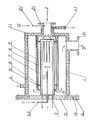
- the device according to the invention essentially consists of a cylindrical hollow body which is arranged in the exhaust gas stream of a plasma etching system between the system and the vacuum pump system and is designed as a reaction chamber 1 and has a bottom 1. 1 with an axially arranged gas inlet opening 2 on one end face.
- the wall of the reaction chamber 1 is double and is provided for a cooling medium which is fed to the cooling space via an inflow 4.
- the drain 4.1 is arranged at a position which is opposite and the most distant from the inflow 4.
- the reaction chamber 1 can be closed with a flange cover 10 by means of a sealing ring 13 and screws 14.
- a further cylindrical hollow body is arranged axially, which is designed as a solid body 7 and is closed on one side with a bottom 1.1.
- the bottom 1.1 is located opposite the inner opening of the gas inlet opening 2, while its open side is arranged at a distance from the flange cover 10.
- a heating device 9 is provided, the coil of which is located near the bottom 1.1 of the solid body 7, the bushings for the electrical connections are located in the flange cover 10, so that when the same is opened, the heating device 9 is completely removed from the solid body 7 can be.
- a pipe 11.2 is provided in the flange cover 10, the opening 11.1 of which is arranged inside the solid body 7, while a connection to a device for supplying a purge gas 11 is made through the other side.
- the solid body 7 is fastened within the reaction chamber 1 in such a way that a hollow cylinder designed as radiation protection 6 is arranged around the solid body 7 by means of inner supports 8 on the Wall of the solid body 7 is supported at a distance and this hollow cylinder of the radiation protection 6 has on its outer wall and, opposite the inner supports 8, outer supports 8.1 which correspond to a further cylinder which is designed as a support body 5 and with the wall of the bottom 1.1 of the reaction chamber 1 is firmly connected.
- a further opening is provided in the area of the gas inlet opening 2 or directly in its gas inlet port 2.1, through which a reaction gas 12 can be supplied to the exhaust gas via a pipe 12.1.
- the solid body 7 consists of iron, argon is used as the purge gas 11 and oxygen is used as the reaction gas 12.
- the purging gas 11 is provided as a shield for the heating coil of the heating device 9 which is freely arranged in the solid body 7 in order to avoid corrosion damage to the same.
- the purging gas 11 is supplied preheated to the solid body 7 in order to avoid temperature losses.
- the treated exhaust gas 3 is removed via an exhaust port 3.1 arranged on the wall of the reaction chamber 1.
- the flange cover 10 is loosened by loosening the screws 14 and the iron chloride can be easily removed from the wall in the interior of the reaction chamber.
- the solid body 7 inserted loosely in the support body 5 by means of the supports 8, 8.1 can also be removed with the radiation protection 6.
- the reaction of the chlorine with the iron is clearly detectable on the solid body 7, from which the time of the exchange and the renewal of the solid body 7 can be derived and carried out. It is also possible to have the consumption of the solid body 7 signaled in good time by means of sensors during operation or to control the exhaust gas flow discharged from the device by means of appropriate measuring devices. If there is evidence of chlorine or chlorine content consequently, the solid body 7 is used up and must be replaced.
- the advantages of the device result in particular from the fact that the chlorine in the exhaust gas from plasma etching systems is completely converted and thus no harmful components are released from the exhaust system into the environment, people are bothered or damaged and corrosion damage is caused.
Landscapes
- Engineering & Computer Science (AREA)
- Chemical & Material Sciences (AREA)
- Health & Medical Sciences (AREA)
- Biomedical Technology (AREA)
- Environmental & Geological Engineering (AREA)
- Analytical Chemistry (AREA)
- General Chemical & Material Sciences (AREA)
- Oil, Petroleum & Natural Gas (AREA)
- Chemical Kinetics & Catalysis (AREA)
- Drying Of Semiconductors (AREA)
- Treating Waste Gases (AREA)
Applications Claiming Priority (2)
| Application Number | Priority Date | Filing Date | Title |
|---|---|---|---|
| DD26385984A DD237951A3 (de) | 1984-06-06 | 1984-06-06 | Vorrichtung zum reinigen halogenhaltiger schadstoffe |
| DD263859 | 1984-06-06 |
Publications (2)
| Publication Number | Publication Date |
|---|---|
| EP0166846A2 true EP0166846A2 (fr) | 1986-01-08 |
| EP0166846A3 EP0166846A3 (fr) | 1987-04-15 |
Family
ID=5557707
Family Applications (1)
| Application Number | Title | Priority Date | Filing Date |
|---|---|---|---|
| EP85100094A Withdrawn EP0166846A3 (fr) | 1984-06-06 | 1985-01-07 | Dispositif pour purifier des gaz d'échappement contenant des halogènes |
Country Status (3)
| Country | Link |
|---|---|
| EP (1) | EP0166846A3 (fr) |
| JP (1) | JPS6157222A (fr) |
| DD (1) | DD237951A3 (fr) |
Cited By (9)
| Publication number | Priority date | Publication date | Assignee | Title |
|---|---|---|---|---|
| EP0176295A3 (fr) * | 1984-09-17 | 1988-01-07 | Randall Mundt | Elimination de matière indésirable d'une conduite de gaz |
| EP0296720A3 (en) * | 1987-06-23 | 1989-08-02 | Kin-Chung Ray Chiu | Plasma extraction reactor and its use for vapor extraction from gases |
| EP0346893A1 (fr) * | 1988-06-15 | 1989-12-20 | Centrotherm Elektrische Anlagen Gmbh + Co. | Dispositif pour purifier des gaz d'échappement d'un procédé CVD |
| WO1993013851A1 (fr) * | 1992-01-16 | 1993-07-22 | Leybold B.V. | Procede, pompe multiple a sec et epurateur a plasma servant a la conversion de gas reactifs |
| US5735919A (en) * | 1995-12-14 | 1998-04-07 | Suntec System Co., Ltd. | Exhaust gas processing system |
| US6041623A (en) * | 1998-08-27 | 2000-03-28 | Lucent Technologies Inc. | Process for fabricating article comprising refractory dielectric body |
| US6576202B1 (en) | 2000-04-21 | 2003-06-10 | Kin-Chung Ray Chiu | Highly efficient compact capacitance coupled plasma reactor/generator and method |
| US9599110B2 (en) | 2011-10-19 | 2017-03-21 | Adixen Vacuum Products | Gas pumping and treatment device |
| US20220299137A1 (en) * | 2021-03-19 | 2022-09-22 | Tokyo Electron Limited | Pipe connection structure and processing apparatus |
Families Citing this family (2)
| Publication number | Priority date | Publication date | Assignee | Title |
|---|---|---|---|---|
| FR2623728B1 (fr) * | 1987-11-30 | 1990-04-06 | Air Liquide | |
| DE4444273C1 (de) * | 1994-12-13 | 1996-06-27 | Umex Gmbh | Vorrichtung zur Reinigung halogenhaltiger Abgase |
Family Cites Families (1)
| Publication number | Priority date | Publication date | Assignee | Title |
|---|---|---|---|---|
| DE2015996A1 (en) * | 1970-03-26 | 1971-10-14 | Richard Kablitz Ges F Oekonomi | Purifying combustion gas contg chlorine |
-
1984
- 1984-06-06 DD DD26385984A patent/DD237951A3/de not_active IP Right Cessation
-
1985
- 1985-01-07 EP EP85100094A patent/EP0166846A3/fr not_active Withdrawn
- 1985-06-06 JP JP60121626A patent/JPS6157222A/ja active Pending
Cited By (14)
| Publication number | Priority date | Publication date | Assignee | Title |
|---|---|---|---|---|
| EP0176295A3 (fr) * | 1984-09-17 | 1988-01-07 | Randall Mundt | Elimination de matière indésirable d'une conduite de gaz |
| EP0296720A3 (en) * | 1987-06-23 | 1989-08-02 | Kin-Chung Ray Chiu | Plasma extraction reactor and its use for vapor extraction from gases |
| EP0346893A1 (fr) * | 1988-06-15 | 1989-12-20 | Centrotherm Elektrische Anlagen Gmbh + Co. | Dispositif pour purifier des gaz d'échappement d'un procédé CVD |
| WO1993013851A1 (fr) * | 1992-01-16 | 1993-07-22 | Leybold B.V. | Procede, pompe multiple a sec et epurateur a plasma servant a la conversion de gas reactifs |
| US5672322A (en) * | 1992-01-16 | 1997-09-30 | Leybold Ag | Method, dry multi-stage pump and plasmascrubber for converting reactive gases |
| US5735919A (en) * | 1995-12-14 | 1998-04-07 | Suntec System Co., Ltd. | Exhaust gas processing system |
| US6041623A (en) * | 1998-08-27 | 2000-03-28 | Lucent Technologies Inc. | Process for fabricating article comprising refractory dielectric body |
| US6576202B1 (en) | 2000-04-21 | 2003-06-10 | Kin-Chung Ray Chiu | Highly efficient compact capacitance coupled plasma reactor/generator and method |
| US6998027B2 (en) | 2000-04-21 | 2006-02-14 | Dryscrub, Etc | Highly efficient compact capacitance coupled plasma reactor/generator and method |
| US7241428B2 (en) | 2000-04-21 | 2007-07-10 | Dryscrub, Etc | Highly efficient compact capacitance coupled plasma reactor/generator and method |
| US9599110B2 (en) | 2011-10-19 | 2017-03-21 | Adixen Vacuum Products | Gas pumping and treatment device |
| TWI610024B (zh) * | 2011-10-19 | 2018-01-01 | 艾迪生真空產品公司 | 泵送並處理氣體之裝置 |
| US20220299137A1 (en) * | 2021-03-19 | 2022-09-22 | Tokyo Electron Limited | Pipe connection structure and processing apparatus |
| US11774017B2 (en) * | 2021-03-19 | 2023-10-03 | Tokyo Electron Limited | Pipe connection structure and processing apparatus |
Also Published As
| Publication number | Publication date |
|---|---|
| DD237951A3 (de) | 1986-08-06 |
| EP0166846A3 (fr) | 1987-04-15 |
| JPS6157222A (ja) | 1986-03-24 |
Similar Documents
| Publication | Publication Date | Title |
|---|---|---|
| DE68919084T2 (de) | Metalloxydierungsanordnung und verfahren. | |
| DE19802404B4 (de) | Vorrichtung zur Gasreinigung sowie Verfahren zur Behandlung eines zu reinigenden Gases | |
| DE3513731C2 (fr) | ||
| EP0702771B1 (fr) | Dispositif d'epuration de gaz brules | |
| DE60132089T2 (de) | Vorrichtung zur behandlung von gasen miitels plasma | |
| EP0166846A2 (fr) | Dispositif pour purifier des gaz d'échappement contenant des halogènes | |
| DE69407933T2 (de) | Verfahren zum Rohrverbinden durch TIG Schweissen | |
| DE4319118A1 (de) | Verfahren und Vorrichtung zur Entsorgung von Fluorkohlenstoffen und anderen fluorhaltigen Verbindungen | |
| DE2647088B2 (de) | Verfahren und Vorrichtung zum Reinigen von Oberflächen | |
| DE19600873A1 (de) | Verfahren und Einrichtung zur Reinigung von schadstoffhaltigen Abgasen durch Verbrennen und chemische Umsetzung mit Hilfe einer Flamme in einer Brennkammer | |
| EP1083978A1 (fr) | Procede d'epuration de gaz de processus utilises | |
| EP0402798A2 (fr) | Dispositif de revêtement | |
| DE3230922A1 (de) | Verfahren zur behandlung von stoffen mit ozon | |
| EP0508338A1 (fr) | Procédé et dispositif pour la photolyse des contaminants organiques à partir de l'eau | |
| EP0347753B1 (fr) | Procédé pour la purification de gaz d'échappement | |
| DE3854081T2 (de) | Verbrennungssystem zur vernichtung schädlicher abfälle. | |
| DE10312309A1 (de) | Verfahren und Vorrichtung zur Reinigung von Abluft | |
| DE19631873C1 (de) | Einrichtung zur Reinigung von schadstoffhaltigen Abgasen in einer Brennkammer mit anschließender Wascheinrichtung | |
| DE3432033C2 (de) | Verfahren und Anordnung zur Entgiftung von F-kohlenstoffhaltigen Abgasen | |
| DE4016514C2 (fr) | ||
| DE19807632A1 (de) | Vorrichtung zum Konzentrieren und Reinigen von Schwefelsäure | |
| EP0487834A1 (fr) | Procédé de lavage oxydant pour purifier des gaz d'échappement | |
| EP0735320B1 (fr) | Procédé et dispositif pour la purification des effluents gazeux nocifs par conversion chimique | |
| EP0340379A2 (fr) | Procédé pour purifier un sol contaminé par des composés organiques hydrophobiques | |
| DE69010418T2 (de) | Verfahren zur Reinigung heisser Flächen von Öfen sowie Einrichtung und Granulat zu dessen Durchführung. |
Legal Events
| Date | Code | Title | Description |
|---|---|---|---|
| PUAI | Public reference made under article 153(3) epc to a published international application that has entered the european phase |
Free format text: ORIGINAL CODE: 0009012 |
|
| AK | Designated contracting states |
Designated state(s): AT CH DE FR IT LI NL |
|
| PUAL | Search report despatched |
Free format text: ORIGINAL CODE: 0009013 |
|
| AK | Designated contracting states |
Kind code of ref document: A3 Designated state(s): AT CH DE FR IT LI NL |
|
| STAA | Information on the status of an ep patent application or granted ep patent |
Free format text: STATUS: THE APPLICATION IS DEEMED TO BE WITHDRAWN |
|
| 18D | Application deemed to be withdrawn |
Effective date: 19870203 |
|
| RIN1 | Information on inventor provided before grant (corrected) |
Inventor name: VOIGT, REINHARD Inventor name: WEBER, ULF Inventor name: FENDLER, REINHARD, DR. Inventor name: BERG, DOROTHEA, DR. Inventor name: LEHMANN, KLAUS-JUERGEN Inventor name: HELBIG, JUERGEN Inventor name: TILLER, HANS-JUERGEN |