EP0166878A2 - Appareil pour faire un test sanguin - Google Patents
Appareil pour faire un test sanguin Download PDFInfo
- Publication number
- EP0166878A2 EP0166878A2 EP85104103A EP85104103A EP0166878A2 EP 0166878 A2 EP0166878 A2 EP 0166878A2 EP 85104103 A EP85104103 A EP 85104103A EP 85104103 A EP85104103 A EP 85104103A EP 0166878 A2 EP0166878 A2 EP 0166878A2
- Authority
- EP
- European Patent Office
- Prior art keywords
- tne
- blood
- droplet
- generating
- test strip
- Prior art date
- Legal status (The legal status is an assumption and is not a legal conclusion. Google has not performed a legal analysis and makes no representation as to the accuracy of the status listed.)
- Granted
Links
Images

Classifications
-
- G—PHYSICS
- G01—MEASURING; TESTING
- G01N—INVESTIGATING OR ANALYSING MATERIALS BY DETERMINING THEIR CHEMICAL OR PHYSICAL PROPERTIES
- G01N21/00—Investigating or analysing materials by the use of optical means, i.e. using sub-millimetre waves, infrared, visible or ultraviolet light
- G01N21/17—Systems in which incident light is modified in accordance with the properties of the material investigated
- G01N21/47—Scattering, i.e. diffuse reflection
- G01N21/4738—Diffuse reflection, e.g. also for testing fluids, fibrous materials
-
- A—HUMAN NECESSITIES
- A61—MEDICAL OR VETERINARY SCIENCE; HYGIENE
- A61B—DIAGNOSIS; SURGERY; IDENTIFICATION
- A61B5/00—Measuring for diagnostic purposes; Identification of persons
- A61B5/145—Measuring characteristics of blood in vivo, e.g. gas concentration or pH-value ; Measuring characteristics of body fluids or tissues, e.g. interstitial fluid or cerebral tissue
- A61B5/14532—Measuring characteristics of blood in vivo, e.g. gas concentration or pH-value ; Measuring characteristics of body fluids or tissues, e.g. interstitial fluid or cerebral tissue for measuring glucose, e.g. by tissue impedance measurement
-
- A—HUMAN NECESSITIES
- A61—MEDICAL OR VETERINARY SCIENCE; HYGIENE
- A61B—DIAGNOSIS; SURGERY; IDENTIFICATION
- A61B5/00—Measuring for diagnostic purposes; Identification of persons
- A61B5/15—Devices for taking samples of blood
- A61B5/150007—Details
- A61B5/150015—Source of blood
- A61B5/150022—Source of blood for capillary blood or interstitial fluid
-
- A—HUMAN NECESSITIES
- A61—MEDICAL OR VETERINARY SCIENCE; HYGIENE
- A61B—DIAGNOSIS; SURGERY; IDENTIFICATION
- A61B5/00—Measuring for diagnostic purposes; Identification of persons
- A61B5/15—Devices for taking samples of blood
- A61B5/150007—Details
- A61B5/150053—Details for enhanced collection of blood or interstitial fluid at the sample site, e.g. by applying compression, heat, vibration, ultrasound, suction or vacuum to tissue; for reduction of pain or discomfort; Skin piercing elements, e.g. blades, needles, lancets or canulas, with adjustable piercing speed
- A61B5/150061—Means for enhancing collection
- A61B5/150068—Means for enhancing collection by tissue compression, e.g. with specially designed surface of device contacting the skin area to be pierced
-
- A—HUMAN NECESSITIES
- A61—MEDICAL OR VETERINARY SCIENCE; HYGIENE
- A61B—DIAGNOSIS; SURGERY; IDENTIFICATION
- A61B5/00—Measuring for diagnostic purposes; Identification of persons
- A61B5/15—Devices for taking samples of blood
- A61B5/150007—Details
- A61B5/150175—Adjustment of penetration depth
- A61B5/150183—Depth adjustment mechanism using end caps mounted at the distal end of the sampling device, i.e. the end-caps are adjustably positioned relative to the piercing device housing for example by rotating or screwing
-
- A—HUMAN NECESSITIES
- A61—MEDICAL OR VETERINARY SCIENCE; HYGIENE
- A61B—DIAGNOSIS; SURGERY; IDENTIFICATION
- A61B5/00—Measuring for diagnostic purposes; Identification of persons
- A61B5/15—Devices for taking samples of blood
- A61B5/150007—Details
- A61B5/150206—Construction or design features not otherwise provided for; manufacturing or production; packages; sterilisation of piercing element, piercing device or sampling device
- A61B5/150305—Packages specially adapted for piercing devices or blood sampling devices
-
- A—HUMAN NECESSITIES
- A61—MEDICAL OR VETERINARY SCIENCE; HYGIENE
- A61B—DIAGNOSIS; SURGERY; IDENTIFICATION
- A61B5/00—Measuring for diagnostic purposes; Identification of persons
- A61B5/15—Devices for taking samples of blood
- A61B5/150007—Details
- A61B5/150343—Collection vessels for collecting blood samples from the skin surface, e.g. test tubes, cuvettes
-
- A—HUMAN NECESSITIES
- A61—MEDICAL OR VETERINARY SCIENCE; HYGIENE
- A61B—DIAGNOSIS; SURGERY; IDENTIFICATION
- A61B5/00—Measuring for diagnostic purposes; Identification of persons
- A61B5/15—Devices for taking samples of blood
- A61B5/150007—Details
- A61B5/150358—Strips for collecting blood, e.g. absorbent
-
- A—HUMAN NECESSITIES
- A61—MEDICAL OR VETERINARY SCIENCE; HYGIENE
- A61B—DIAGNOSIS; SURGERY; IDENTIFICATION
- A61B5/00—Measuring for diagnostic purposes; Identification of persons
- A61B5/15—Devices for taking samples of blood
- A61B5/150007—Details
- A61B5/150374—Details of piercing elements or protective means for preventing accidental injuries by such piercing elements
- A61B5/150381—Design of piercing elements
- A61B5/150412—Pointed piercing elements, e.g. needles, lancets for piercing the skin
-
- A—HUMAN NECESSITIES
- A61—MEDICAL OR VETERINARY SCIENCE; HYGIENE
- A61B—DIAGNOSIS; SURGERY; IDENTIFICATION
- A61B5/00—Measuring for diagnostic purposes; Identification of persons
- A61B5/15—Devices for taking samples of blood
- A61B5/150007—Details
- A61B5/150755—Blood sample preparation for further analysis, e.g. by separating blood components or by mixing
-
- A—HUMAN NECESSITIES
- A61—MEDICAL OR VETERINARY SCIENCE; HYGIENE
- A61B—DIAGNOSIS; SURGERY; IDENTIFICATION
- A61B5/00—Measuring for diagnostic purposes; Identification of persons
- A61B5/15—Devices for taking samples of blood
- A61B5/150007—Details
- A61B5/150801—Means for facilitating use, e.g. by people with impaired vision; means for indicating when used correctly or incorrectly; means for alarming
- A61B5/150809—Means for facilitating use, e.g. by people with impaired vision; means for indicating when used correctly or incorrectly; means for alarming by audible feedback
-
- A—HUMAN NECESSITIES
- A61—MEDICAL OR VETERINARY SCIENCE; HYGIENE
- A61B—DIAGNOSIS; SURGERY; IDENTIFICATION
- A61B5/00—Measuring for diagnostic purposes; Identification of persons
- A61B5/15—Devices for taking samples of blood
- A61B5/151—Devices specially adapted for taking samples of capillary blood, e.g. by lancets, needles or blades
- A61B5/15101—Details
- A61B5/15103—Piercing procedure
- A61B5/15105—Purely manual piercing, i.e. the user pierces the skin without the assistance of any driving means or driving devices
-
- A—HUMAN NECESSITIES
- A61—MEDICAL OR VETERINARY SCIENCE; HYGIENE
- A61B—DIAGNOSIS; SURGERY; IDENTIFICATION
- A61B5/00—Measuring for diagnostic purposes; Identification of persons
- A61B5/15—Devices for taking samples of blood
- A61B5/151—Devices specially adapted for taking samples of capillary blood, e.g. by lancets, needles or blades
- A61B5/15186—Devices loaded with a single lancet, i.e. a single lancet with or without a casing is loaded into a reusable drive device and then discarded after use; drive devices reloadable for multiple use
-
- A—HUMAN NECESSITIES
- A61—MEDICAL OR VETERINARY SCIENCE; HYGIENE
- A61B—DIAGNOSIS; SURGERY; IDENTIFICATION
- A61B5/00—Measuring for diagnostic purposes; Identification of persons
- A61B5/15—Devices for taking samples of blood
- A61B5/157—Devices characterised by integrated means for measuring characteristics of blood
-
- A—HUMAN NECESSITIES
- A61—MEDICAL OR VETERINARY SCIENCE; HYGIENE
- A61B—DIAGNOSIS; SURGERY; IDENTIFICATION
- A61B5/00—Measuring for diagnostic purposes; Identification of persons
- A61B5/74—Details of notification to user or communication with user or patient; User input means
- A61B5/7405—Details of notification to user or communication with user or patient; User input means using sound
-
- G—PHYSICS
- G01—MEASURING; TESTING
- G01N—INVESTIGATING OR ANALYSING MATERIALS BY DETERMINING THEIR CHEMICAL OR PHYSICAL PROPERTIES
- G01N21/00—Investigating or analysing materials by the use of optical means, i.e. using sub-millimetre waves, infrared, visible or ultraviolet light
- G01N21/17—Systems in which incident light is modified in accordance with the properties of the material investigated
- G01N21/47—Scattering, i.e. diffuse reflection
- G01N21/4738—Diffuse reflection, e.g. also for testing fluids, fibrous materials
- G01N2021/4776—Miscellaneous in diffuse reflection devices
- G01N2021/478—Application in testing analytical test strips
Definitions
- This invention relates to biological fluid testing instruments, and is particularly useful in an instrument for use by vision-impaired persons for determining the concentration of a medically significant component of their body fluids, such as glucose content of blood.
- Various types of equipment are known for conducting what is known as reflected-light photometry, in which the reflectivity of a so-called objective area of a test strip is determined.
- the objective area is specifically dedicated for the determination of a certain property, for example, concentration of a medically significant component of a biological fluid such as blood or urine.
- the component which is studied is rendered capable of study through a reaction that occurs on the test strip.
- the objective area undergoes a reflectivity change as a result of the reaction of a reagent material on the objective area with the component of the biological fluid. This change in reflectivity is evaluated to determine the concentration of tne medically significant component in the biological fluid.
- the utilizaticn of test strips and associated instruments to aetermine medically significant quantitative parameters is known. High precision instruments for achieving quantitative determinations of this type are available. There is, for example, the REFLOCHECK blood glucose monitor available from Boehringer Mannhe im GmbH, West Germany.
- an apparatus for sequentially forming droplets of a biological fluid of a controlled, generally uniform size from the body of the user of the apparatus.
- the apparatus includes a first surface across which the biological fluid flows from the body under the influence of gravity.
- the first surface includes a first edge terminating at a point.
- a second surface is provided for collecting the droplets of the biological fluid.
- the second surface is disposed beneath the point to catch a droplet as the biological fluid flows downward along the first surface, collects at the point where it forms into the drooplet of the controlled, generally uniform size, and, owing to gravity and the surface tension of the biological fluid, falls toward the second surface as a generally uniformly sized droplet.
- the first edge of the first surface is a vertically lower edge of the first surface
- tine first surface further includes a second, vertically upper edge.
- the biological fluid is blood and is removed from the body of the user by pricking the skin, "milking" the body surface in the region in which the skin is pricked across the second edge of the first surface to supply to the first surface a small amount of blood which flows downward across the first surface toward the point, where it forms into the droplet of generally uniform size.
- the second surface is the surface of the objective area of a test strip, and contains a reagent for a medically significant component of the body fluid.
- the droplet must be of a controlled, generally uniform size to insure an appropriate reaction rate between the reagent and the medically significant component of the body fluid.
- such an instrument is provided with means for indicating a physical characteristic or parameter of medical significance of a body fluid including means for generating an audible indication of the physical characteristic or parameter.
- the physical characteristic or parameter is glucose content
- the body fluid is blood.
- the instrument comprises means for generating a data signal related to the reflectance of a reacted test strip.
- the means for generating the audible indication of glucose content comprises a speech generator and means for coupling the speech generator to the data signal generator for reporting the reflectance output as glucose content.
- the apparatus further comprises a light source, a photodetector and means for mounting the light source and photodetector vertically above the test strip a distance such that formation of a droplet of blood of a generally uniform size on the test strip interrupts the passage of light between the light source and photodetector.
- the apparatus further includes means responsive to the interruption of light to produce a first audible indication that a droplet of tne generally uniform size has been formed on the test strip. Further according to an illustrative embodiment, the apparatus comprises means for timing an interval following the first audible indication and for producing a second audible indication that the reaction between the reagent on the test strip and the blood glucose has reached a point at which the glucose content is to be read.
- the system of the present invention is housed in a case 10 including a base 12 and a hinged lid 14.
- the base 12 includes compartments for alcohol wipes 16, cotton balls 18, a plug-in power adapter 20, a tool 22 for puncturing the skin of a user, a plurality of heads 24 for use in conjunction with puncture tool 22 to adjust the depth of the puncture, sterile lancettes 26 for use in conjunction with tool 22 and heads 24 to perform the puncture, a container 28 for reagent-carrying test strips, a calendar 30, a test-strip reading unit 32 such as the REFLOCHECK TM blood glucose monitor, and a cassette tape 34 containing directions for the use of the system
- a blood transfer assembly fixture 36 is attached to the base 12 near the front center of the base 12 for easy access by the user.
- the blood transfer assembly fixture 36 includes a mounting base 38 with a flat generally planar forward region 40 and a rear wall 42 which extends along two parallel sides 44, 46 and across the back of the mounting base 38 to define a forwardly opening region 50.
- Base 38 is illustratively constructed from an easily cleanable material such as, for example, ABS synthetic resin.
- Base 38 includes locator pins 52, 54 molded along the opposite parallel sides 44, 46 of the mounting base 38 forward of the forward terminations of wall 42.
- Blood transfer assembly fixture 36 also includes a blood transfer base 56. Tapered holes 61 open into the bottom 62 of the blood transfer base 56, for receiving locator pins 52, 54, respectively to locate base 56 on the fixture base 38. Side walls 58, 60 also include finger grip recesses 64 which facilitate removal of blood transfer base 56 from fixture base 38 for cleaning.
- the top surface of blood transfer base 56 includes a forward generally upwardly concave region 66 and a rearward generally planar region 68. Region 68 lies generally within the region 50 formed by wall 42 when the blood transfer base 56 is positioned on locator pins 52, 54 and moved downwardly into fixture base 38.
- An upwardly concave groove 70 extends rearward from the front of the blood transfer base 56.
- a narrow, flat land region 72 is provided between each side edge of groove 70 and the adjacent upwardly concave portion 66 of the base.
- the blood transfer base 56 includes a stop 74 formed rearward of the rear end of groove 70.
- a "funnel" 76 is hinged to the wall 58 providing the forward upwardly concave region 66 of blood transfer base 56 by a stainless steel hinge pin 78 which is press-fitted through a downwardly extending ear 80 formed on a side wall of the funnel 76, and an aligned hole provided in the side wall 58.
- the opposite side wall ear 82 of funnel 76 extends downward farther onto the opposite side wall 60 forming region 66.
- This opposite side wall 60 is provided with a part-spherical recess 84, illustrated in broken lines in Figs. 2-3, forming one component of a latch mechanism.
- Other components of the latch mechanism include an elongated handle 86 which is molded as part of the funnel 76 on ear 82, and a ball plunger mechanism including a spring 88-loaded ball 90.
- the ball plunger is housed within a generally right circular cylindrical hole which extends axially of the handle 86.
- the ball 90 engages the part-spherical recess 84 when the funnel 76 is pivoted in the direction of the arrow in Fig.
- the funnel 76 is provided with a downwardly extending projection 92 between ears 80, 82, such that, when the funnel 76 is in its downward position and latched, the projection 92 extends to substantially the same vertical height as the land regions 72 on either side of the groove 70.
- the funnel 76 includes a rearwardly facing surface 94 including a lower edge 96 terminating at a point 98 directly above the transverse center of groove 70.
- Surface 94 also includes an upper edge 100 formed by the intersection of surface 94 with an upwardly concave upper surface 102 of the funnel 76.
- the blood transfer assembly 36 works in the following manner: a reagent-bearing test strip 104 is removed from container 28 and inserted longitudinally of blood transfer base 56 to be supported on the lands 72 on either side of groove 70. The strip 104 is inserted into the blood transfer base 56 until it encounters the stop 74 at the rearward end thereof. The funnel 76 is then pivoted downward until the ball 90 engages recess 84, locking the funnel 76 in the downward position. In this position, the projection 92 holds the strip 104 fairly securely against the lands 72, so that the position of the strip 104 is fairly fixed. The skin of the finger of the user is then pricked, using the puncture tool 22, one of heads 24 and one of lancettes 26 in known manner.
- the region of the finger around the opening in the skin is then worked or "milked" across the somewhat finger-shaped upwardly concave surface 102, as indicated by arrow 105 in Fig. 3, to collect blood along edge 100.
- the blood scraped from the skin and collected along edge 100 moves under the influence of gravity down the surface 94 and, owing to gravity and the surface tension of the blood, forms into a substantially uniformly sized droplet at the point 98 directly above the reagent-bearing region 105 of test strip 104.
- the blood droplet of substantially uniform size drops from point 98 onto the reagent-bearing region 105 of strip 104 which is positioned directly beneath point 98 by the lands 72 and stop pin 74.
- the monitoring base 38 is provided with a photoemitter 106 and photodetector 108.
- Photoemitter 1(6 is provided in side wall 46.
- Photodetector 108 is provided in side wall 44.
- the photoemitter 106 and photodetector 108 are aligned axially, are positioned vertically along side walls 44, 46 at sufficient heights to insure that a droplet of the appropriate size will interrupt the current of light passing between the photoemitter 106 and photodetector 108, and are both recessed into their respective side walls 44, 46 to insure minimal interference from ambient light.
- the droplet breaks the current of light from photoemitter 106 to photodetector 108 as it falls onto the reagent-bearinq region of test strip 104. As the droplet spreads, its vertical height decreases slightly, until its surface tension balances the gravitational force tending to flatten the droplet.
- the photodetector 108 typically is one exhibiting some hysteresis.
- the strips 104 generally are dated, since many of the reagents with which test strips are provided can age. Aging can affect the ability of the reagents in test strips to react with medically significant components of biological fluids.
- the calendar 30 of Fig. 1 is provided in recognition of this fact. Calendar 30 includes a number of magnetically backed numerals, four 110, 112, 114, 116 of which can be displayed at any given time on upper surface 118 of base 12. A magnetic strip is provided on surface 118 which cooperates with the backs of the numerals.
- the left-most numeral 110 as viewed in Fig. 1 is the more significant digit of the month in which the test strips 104 expire.
- Numeral 112 is the less significant digit of this month.
- Numeral l14 is the more significant digit of a two-digit year representation.
- Numeral 116 is the less significant digit of the two-digit year representation. The numerals are raised, making them easily readable by users with impaired vision.
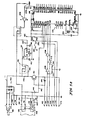
- the base 12 houses the photoemitter 106 and photodetector 108 as previously discussed.
- the illustrative photoemitter 106 is a light-emitting diode (LED) and photodetector 108 is typically an integrated circuit including a phototransistor, an amplifier and a wave-shaping circuit.
- the anode 132 of LED 106 is coupled through a resistor 134 to a VCC positive potential source, illustratively +5V.
- the cathode 136 of LED 106 is coupled to a suitable common circuit terminal, ground.
- a power supply terminal 138 of photodetector 108 is also coupled to the VCC supply.
- the common terminal 140 of photodetector 108 is coupled to ground.
- a capacitor 142 is coupled across terminals 138, 140.
- the output terminal 144 of photodetector 108 is coupled through a resistor 146 to a conductor 148 which provides the DROP DETECT output signal.
- the base 12 is provided with an unregulated battery source 150, illustratively comprising a pair of +9V batteries in parallel.
- the output terminal 152 of battery 150 provides +9V with respect to circuit ground
- a switch 154 controls the availability of +9V at terminal 1 52. If external power is available, the plug-in power adapter 20 of Fig. 1 can be used.
- Adapter 20 is a 120 V AC to +9VDC converter with a plug-in jack 155. Jack 155 disconnects battery 150 from the circuit when the jack is plugged into the switch 154 as shown in broken lines in Fig. 5a.
- the battery 150 also provides power to the blood glucose monitor 32 through terminals 156, 158.
- Fig. 5a also illustrates terminals for signals available from the blood glucose monitor 32, if the REFLOCHECKTM monitor is used.
- the signals available at these terminals include a POWER ON signal available on terminal 160, a DATA signal available on terminal 162, a CLOCK signal available on terminal 164, and a common ground connection at terminal 166.
- a TEST signal is available at terminal 168, and a language signal, LANG, is available at terminal 170.
- a terminal 172 also provides a common ground.
- a small speaker 174 (Fig. 5b) with conductors 176, 178 is mounted in the base 12 for communicating outputs from the system to the user.
- Conductor 152 couples battery voltage through a resistor 180 to the collector of a transistor 182.
- the emitter of transistor 182 is coupled to ground.
- the base of transistor 182 is coupled to the POWER ON terminal 160, and through a capacitor 184 to ground.
- Signal from the collector of transistor 182 is coupled through a series resistor 186 to the gate of a P-channel insulated gate field-effect transistor (IGFET) regulator 190.
- IGFET insulated gate field-effect transistor
- FET 190 may be a type IFRD 9123 FET.
- the source and other gate of FET 190 are coupled to conductor 152.
- the drain of FET 190 is coupled through a capacitor 192 to ground and provides a regulated voltage VA approximately equal to the battery voltage, e.g., +9V.
- the drain of FET 190 is also coupled to an input terminal, pin 1, of an intergrated circuit voltage regulator 194, such as the type LM 7805 CT regulator.
- Pin 2 the ground terminal, of regulator 194 is coupled to the circuit ground.
- the output terminal, pin 3 of regulator 194 is coupled through a capacitor 196 to ground, and forms the regulated VCC terminal of the circuit.
- the TEST terminal 168, the DROP DETECT line 148 and the LANG terminal 170 are coupled through resistors 200, 202, 204, respectively, to VCC.
- the DATA terminal 162 is coupled to an input terminal of ah inverting amplifier 206
- the output terminal of inverting amplifier 206 is coupled to an inverting input terminal of an amplifier 208.
- the input terminal of amplifier 206 is also coupled to ground through a resistor 210.
- the CLOCK terminal 164 is coupled to an input terminal of an inverting amplifier 212.
- the input terminal of amplifier 212 is also coupled to ground through a resistor 214.
- the TEST terminal 168 is also coupled to an input terminal Al, pin 34, of a microcomputer 216, such as the Motorola MC 68705 U3L.
- the Cl input terminal, pin 10, of microcomputer 216 is coupled to the DROP DETECT conductor 148.
- the A6 terminal, pin 39, of microcomputer 216 is coupled to the LANG terminal 170.
- the CO terminal, pin 9, of microcomputer 216 is coupled to the output terminal of amplifier 208.
- the INT terminal, pin 3, of microcomputer 216 is coupled to the output terminal of inverting amplifier 212. Terminals A2, A3, A4 and A7, pins 35, 36, 37, and 40, respectively, of microcomputer 216 are coupled through a resistor 218 to VCC.
- Terminals VPP and VCC, pins 7 and 4, respectively, of microcomputer 216 are also coupled to VCC.
- Terminals VSS and TMR/BOOT, pins 1 and 8, respectively, of microcomputer 216 are coupled to the circuit ground.
- the RST terminal, pin 2 of microcomputer 216 is coupled through a capacitor 220 to ground.
- a 4.0 MHz crystal 222 is coupled across the EXTAL and XTAL terminals, pins 5 and 6, respectively, of microcomputer 216.
- a capacitor 224 is coupled between pin 5 of microcomputer 216 and ground.
- the A5 terminal, pin 38, of microcomputer 216 is coupled to an input terminal of an inverting amplifier 226.
- the input terminal of amplifier 226 is also coupled to ground through a resistor 228.
- the output terminal of amplifier 226 is coupled to a gate electrode of a P-channel IGFET, whose source and other gate are connected to VCC and whose drain provides a standby voltage VSBY.
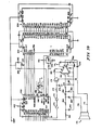
- the B7, B6, B5, B4, B3, B2, Bl, BO, A0, C2 and C3 terminals, pins 32, 31, 30, 29, 28, 27, 26, 25, 33, 11 and 12, respectively, of microcomputer 216 are coupled, respectively, to (Fig.
- speech controller integrated circuit 230 is a type SP0256-AL2 integrated circuit speech controller microprocessor available from General Instruments.
- the VSS terminal of circuit 230 is coupled to ground.
- the SE, TEST and VD1 terminals, pins 19, 22, 23, respectively, of circuit 230 are coupled to VCC.
- the VDD terminal, pin 7, of circuit 230 is coupled to VSBY (Fig. 5a).
- the SER OUT, SER IN, Cl, C2, C3 and ROM DISABLE terminals, pins 12, 21, 4, 5, 6 and 3, respectively, of circuit 230 are coupled, respectively, to the SER IN, SER OUT, Cl, C2, C3 and ROM ENA terminals, pins 25, 9, 15, 14, 13 and 8, respectively, of a serial-to-parallel converter integrated circuit 232 such as the SPR 000 available from General Instruments.
- the VDD and CS1 terminals, pins 26 and 6, respectively, of circuit 232 are coupled to VSBY.
- the VSS and CS2 terminals, pins 1 and 7, respectively, of circuit 232 are coupled to ground.
- the ROM CLK terminal, pin 27, of circuit 232 is coupled to the ROM CLK terminal, pin 26, of speech controller 230.
- Speech ROM capacity is provided by a speech ROM 234, such as the type 27128 speech ROM available from Seeq.
- the connections between the serial-to-parallel converter 232 and speech ROM 234 are as follows: terminals DO-D7, pins 35-28 respectively, of circuit 232 are coupled, respectively, to terminals 00-07 pins 11, 12, 13, 15, 16, 17, 18 and 19, respectively, of speech R OM 234. Terminals AO-A13, pins 24, 23, 22, 21, 20, 19, 18, 17, 16, 12, 11, 5, 3 and 40, respectively, of circuit 232 are coupled, respectively, to terminals AO-A13, pins 10, 9, 8, 7, 6, 5, 4, 3, 25, 24, 21, 23, 2 and 26, respectively, of speech ROM 234. Terminals VPP, VCC and PGM, pins 1, 28 and 27, respectively, of speech ROM 234 are coupled to VSBY. Terminals CE, OE and GND, pins 20, 22, and 14, respectively, of speech ROM 234 are coupled to circuit ground.
- a 3.12 MHz crystal 236 is coupled across terminals OSC1 and OSC2, pins 27, 28, respectively, of speech controller 230. These terminals are also coupled to ground through capacitors 238.
- a parallel circuit including a resistor 240 and diode 242 is coupled between VSBY and the RST terminal, pin 2, of speech controller 230.
- the cathode of diode 242 is coupled to VSBY and its anode is coupled to ground through capacitor 244.
- a similar circuit including a parallel resistor 246 and diode 248 is coupled between VCC and the SBY RST terminal, pin 25, of speech controller 230.
- the cathode of diode 248 is coupled to VCC and its anode is coupled to ground through a capacitor 250.
- the audio frequency analog output of the speech controller circuit 230 appears at its DAC OUT terminal, pin 24.
- This signal is coupled through a multiple-section R-C filter including resistor 252, resistor 254, capacitor 256 and resistor 258 in series, to the + input terminal, pin 3, of an amplifier 260, such as the type LM386-4.
- the junction of resistors 252 and 254 is coupled to ground through a capacitor 262.
- the junction of resistor 254 and capacitor 256 is coupled to ground through a capacitor 264.
- the junction of capacitor 256 and resistor 258 is coupled to ground through a resistor 266.
- Pin 3 of amplifier 260 is coupled to ground through a resistor 268.
- the - input terminal, pin 2, of amplifier 260 is coupled to ground.
- Pins 12, 8 of circuits 216 are coupled to an input terminal of an inverting amplifier 270.
- the output terminal of amplifier 270 is coupled to an inverting input terminal of an amplifier 272.
- the output terminal of amplifier 272 is coupled through a resistor 274 to the base of a muting transistor 276, and through a capacitor 278 to ground.
- the emitter of transistor 276 is coupled to ground. Its collector is coupled to pin 1 of amplifier 260 and through a capacitor 280 to pin 8 of amplifier 260.
- Pin 6 of amplifier 260 is coupled to VA.
- Pin 7 of amplifier 260 is coupled through a capacitor 282 to ground and pin 4 of amplifier 260 is coupled to ground.
- the output terminal, pin 5, of amplifier 260 carries amplified audio information, such as the glucose content as read by the blood glucose monitor 32 and transmitted to the circuitry of Figs. 5a-5b through the DATA terminal 162.
- the speech controller circuitry also generates an audible signal when a droplet of the substantially uniform size has dropped onto the test strip 104 so that the user can stop supplying blood to the strip.
- the speech controller circuitry then times the interval between placement of the blood droplet on the test strip 104 and the end of the reaction interval, at which time the speech controller instructs the user to wipe the blood droplet off the test strip and insert the test strip into the blood glucose monitor 32 for reading of the blood glucose level.
- the various CLK, and other undesired, frequencies generated in the speech controller and related circuitry are removed by the multiple-section R-C filter on the input terminal, pin 3 of amplifier 260. Audio frequency output is provided to the speaker conductors 176, 178 through DC blocking capacitor 284. The output terminal, pin 5, of amplifier 260 is also coupled to ground through a series R-C circuit 286, 288.
- the circuit is provided with a language jumper terminal pair 290, 292.
- Terminal 290 is coupled to ground.
- Terminal 292 is coupled to LANG terminal 170.
- Application of a conductor across terminals 290, 292 grounds terminal A6, pin 39, of microcomputer 216. If the microcomputer 216 and speech controller 230 are programmed to provide speech in multiple languages, such as, for example, English and German, this provides a handy technique for converting from one language to the other.
- Exhibit A is a source listing for microcomputer 216.
- Exhibit B is an object code for speech ROM 234.
Landscapes
- Health & Medical Sciences (AREA)
- Life Sciences & Earth Sciences (AREA)
- Physics & Mathematics (AREA)
- General Health & Medical Sciences (AREA)
- Engineering & Computer Science (AREA)
- Pathology (AREA)
- Veterinary Medicine (AREA)
- Animal Behavior & Ethology (AREA)
- Surgery (AREA)
- Public Health (AREA)
- Biophysics (AREA)
- Molecular Biology (AREA)
- Biomedical Technology (AREA)
- Heart & Thoracic Surgery (AREA)
- Medical Informatics (AREA)
- Hematology (AREA)
- Dermatology (AREA)
- Immunology (AREA)
- General Physics & Mathematics (AREA)
- Biochemistry (AREA)
- Analytical Chemistry (AREA)
- Chemical & Material Sciences (AREA)
- Emergency Medicine (AREA)
- Optics & Photonics (AREA)
- Pain & Pain Management (AREA)
- Diabetes (AREA)
- Manufacturing & Machinery (AREA)
- Investigating Or Analysing Biological Materials (AREA)
- Prostheses (AREA)
Priority Applications (1)
| Application Number | Priority Date | Filing Date | Title |
|---|---|---|---|
| AT85104103T ATE67385T1 (de) | 1984-04-06 | 1985-04-04 | Bluttestapparat. |
Applications Claiming Priority (4)
| Application Number | Priority Date | Filing Date | Title |
|---|---|---|---|
| US59751284A | 1984-04-06 | 1984-04-06 | |
| US597512 | 1984-04-06 | ||
| US597513 | 1984-04-06 | ||
| US06/597,513 US4661319A (en) | 1984-04-06 | 1984-04-06 | Blood transfer assembly |
Publications (3)
| Publication Number | Publication Date |
|---|---|
| EP0166878A2 true EP0166878A2 (fr) | 1986-01-08 |
| EP0166878A3 EP0166878A3 (en) | 1987-10-14 |
| EP0166878B1 EP0166878B1 (fr) | 1991-09-18 |
Family
ID=24391834
Family Applications (1)
| Application Number | Title | Priority Date | Filing Date |
|---|---|---|---|
| EP85104103A Expired - Lifetime EP0166878B1 (fr) | 1984-04-06 | 1985-04-04 | Appareil pour faire un test sanguin |
Country Status (4)
| Country | Link |
|---|---|
| US (2) | US4661319A (fr) |
| EP (1) | EP0166878B1 (fr) |
| AT (1) | ATE67385T1 (fr) |
| DE (1) | DE3584116D1 (fr) |
Cited By (4)
| Publication number | Priority date | Publication date | Assignee | Title |
|---|---|---|---|---|
| EP0256806A3 (en) * | 1986-08-13 | 1988-11-23 | Lifescan Inc | Method and apparatus for the determination of analytes |
| EP0350049A3 (fr) * | 1988-07-06 | 1991-03-20 | Kabushiki Kaisha Toshiba | Procédé et système de génération d'un signal d'alarme dans un analyseur chimique automatique |
| US5448900A (en) * | 1994-05-02 | 1995-09-12 | Whirlpool Corporation | System for automatically opening basket doors of a top loading horizontal axis automatic washer |
| EP2251691A4 (fr) * | 2008-01-16 | 2011-01-26 | Panasonic Corp | Procédé d'analyse d'un échantillon de solution et appareil pour analyser un échantillon de solution |
Families Citing this family (31)
| Publication number | Priority date | Publication date | Assignee | Title |
|---|---|---|---|---|
| US4661319A (en) * | 1984-04-06 | 1987-04-28 | Boehringer Mannheim Diagnostics, Inc. | Blood transfer assembly |
| AU1816888A (en) * | 1987-06-26 | 1989-01-05 | Gerrard Abdool Rayman | Device for testing fluids |
| USD360031S (en) | 1993-02-25 | 1995-07-04 | Davis Martin R | Combined finger cradle and dropper for blood testing machine |
| USD360033S (en) | 1993-08-27 | 1995-07-04 | Davis Martin R | Combined finger cradle and dropper for blood testing machine |
| USD360032S (en) | 1993-08-27 | 1995-07-04 | Davis Martin R | Combined finger cradle and dropper for blood testing machine |
| US6458326B1 (en) | 1999-11-24 | 2002-10-01 | Home Diagnostics, Inc. | Protective test strip platform |
| US6541266B2 (en) | 2001-02-28 | 2003-04-01 | Home Diagnostics, Inc. | Method for determining concentration of an analyte in a test strip |
| US6562625B2 (en) | 2001-02-28 | 2003-05-13 | Home Diagnostics, Inc. | Distinguishing test types through spectral analysis |
| US6525330B2 (en) | 2001-02-28 | 2003-02-25 | Home Diagnostics, Inc. | Method of strip insertion detection |
| IL146776A (en) * | 2001-11-27 | 2010-11-30 | Yoram Alroy | Device for blood sampling under vacuum conditions |
| US7004928B2 (en) | 2002-02-08 | 2006-02-28 | Rosedale Medical, Inc. | Autonomous, ambulatory analyte monitor or drug delivery device |
| CN1270186C (zh) * | 2002-06-03 | 2006-08-16 | 李祖强 | 能够测定多项生理指标的家庭多功能健康检测仪 |
| US7052652B2 (en) | 2003-03-24 | 2006-05-30 | Rosedale Medical, Inc. | Analyte concentration detection devices and methods |
| US7608042B2 (en) * | 2004-09-29 | 2009-10-27 | Intellidx, Inc. | Blood monitoring system |
| US20060281187A1 (en) | 2005-06-13 | 2006-12-14 | Rosedale Medical, Inc. | Analyte detection devices and methods with hematocrit/volume correction and feedback control |
| CA2624059C (fr) * | 2005-09-30 | 2019-04-02 | Intuity Medical, Inc. | Cartouche d'echantillonnage et d'analyse de fluide corporel multi-site |
| US8801631B2 (en) | 2005-09-30 | 2014-08-12 | Intuity Medical, Inc. | Devices and methods for facilitating fluid transport |
| US20070270677A1 (en) * | 2006-05-22 | 2007-11-22 | Steve Thuss | Interactive device for monitoring and reporting glucose levels |
| US8372015B2 (en) * | 2006-08-28 | 2013-02-12 | Intuity Medical, Inc. | Body fluid sampling device with pivotable catalyst member |
| WO2009145920A1 (fr) * | 2008-05-30 | 2009-12-03 | Intuity Medical, Inc. | Dispositif de prélèvement de liquide organique et interface de site de prélèvement |
| DK3639744T3 (da) | 2008-06-06 | 2022-02-21 | Intuity Medical Inc | Blodglukosemåler og fremgangsmåde til anvendelse |
| JP5642066B2 (ja) | 2008-06-06 | 2014-12-17 | インテュイティ メディカル インコーポレイテッド | 体液の試料内に含まれている検体の存在または濃度を決定する検定を行う方法および装置 |
| US8758267B2 (en) * | 2009-03-17 | 2014-06-24 | Nova Biomedical Corporation | Modified lancet carrier for single-use lancet sensor assembly |
| WO2011065981A1 (fr) | 2009-11-30 | 2011-06-03 | Intuity Medical, Inc. | Dispositif et procédé de fourniture de matériau d'étalonnage |
| WO2012048388A1 (fr) | 2010-10-15 | 2012-04-19 | Atomo Diagnostics Pty Limited | Ensemble d'échantillonnage |
| US20130131479A1 (en) | 2010-03-19 | 2013-05-23 | John Michael Kelly | Diagnostic system |
| US10330667B2 (en) | 2010-06-25 | 2019-06-25 | Intuity Medical, Inc. | Analyte monitoring methods and systems |
| US9782114B2 (en) | 2011-08-03 | 2017-10-10 | Intuity Medical, Inc. | Devices and methods for body fluid sampling and analysis |
| AU345335S (en) | 2012-10-03 | 2012-11-02 | Atomo Diagnostics Pty Ltd | Device for collecting and testing a fluid sample |
| JP2016522070A (ja) | 2013-06-21 | 2016-07-28 | インテュイティ メディカル インコーポレイテッド | 可聴フィードバックを用いた分析物モニタリングシステム |
| WO2015075677A1 (fr) | 2013-11-21 | 2015-05-28 | Atomo Diagnostics Pty Limited | Contrôle de fluide dans des dispositifs de test intégrés |
Family Cites Families (12)
| Publication number | Priority date | Publication date | Assignee | Title |
|---|---|---|---|---|
| US2232029A (en) * | 1938-05-25 | 1941-02-18 | Soc Of Chemical Ind | Drop dispensing vessel |
| US2343610A (en) * | 1942-09-07 | 1944-03-07 | Victor Metal Products Corp | Dropper and pourer cap |
| CH336620A (fr) * | 1956-09-10 | 1959-02-28 | Claude Sanz Manuel | Appareil pour transvaser de petites quantités déterminées d'un liquide |
| CH500707A (fr) * | 1968-07-26 | 1970-12-31 | Micromedic Systems Inc | Dispositif pour effectuer une prise de sang percutanée et digitale |
| US3633566A (en) * | 1969-05-15 | 1972-01-11 | Systematics | Blood collecting method and device |
| US3933439A (en) * | 1974-04-29 | 1976-01-20 | Mcdonald Bernard | Blood collection device |
| US4210026A (en) * | 1978-12-29 | 1980-07-01 | Corning Glass Works | Blood sample collecting means |
| US4317473A (en) * | 1979-12-31 | 1982-03-02 | Becton, Dickinson And Company | Fluid flow control assembly |
| FR2508305B1 (fr) * | 1981-06-25 | 1986-04-11 | Slama Gerard | Dispositif pour provoquer une petite piqure en vue de recueillir une goutte de sang |
| US4397956A (en) * | 1981-12-10 | 1983-08-09 | Maggio Edward T | Means for monitoring the status of control of ketoacidosis-prone diabetics |
| EP0097748A1 (fr) * | 1982-06-28 | 1984-01-11 | Gérard Joseph Slama | Dispositif pour provoquer une petite piqure en vue de recueillir une goutte de sang |
| US4661319A (en) * | 1984-04-06 | 1987-04-28 | Boehringer Mannheim Diagnostics, Inc. | Blood transfer assembly |
-
1984
- 1984-04-06 US US06/597,513 patent/US4661319A/en not_active Expired - Lifetime
-
1985
- 1985-04-04 EP EP85104103A patent/EP0166878B1/fr not_active Expired - Lifetime
- 1985-04-04 AT AT85104103T patent/ATE67385T1/de not_active IP Right Cessation
- 1985-04-04 DE DE8585104103T patent/DE3584116D1/de not_active Expired - Lifetime
-
1986
- 1986-10-06 US US06/915,977 patent/US4765344A/en not_active Expired - Lifetime
Cited By (13)
| Publication number | Priority date | Publication date | Assignee | Title |
|---|---|---|---|---|
| SG83640A1 (en) * | 1986-08-13 | 2001-10-16 | Lifescan Inc | Method of operation of reflectance-reading devices |
| EP0473241A3 (en) * | 1986-08-13 | 1992-07-15 | Lifescan Inc | Method of operation of reflectance-reading devices |
| EP0479394A3 (en) * | 1986-08-13 | 1992-07-15 | Lifescan Inc | Method and apparatus for the determination of analytes |
| US5304468A (en) * | 1986-08-13 | 1994-04-19 | Lifescan, Inc. | Reagent test strip and apparatus for determination of blood glucose |
| EP0256806A3 (en) * | 1986-08-13 | 1988-11-23 | Lifescan Inc | Method and apparatus for the determination of analytes |
| US6821483B2 (en) | 1986-08-13 | 2004-11-23 | Lifescan, Inc. | Reagents test strip with alignment notch |
| US6858401B2 (en) | 1986-08-13 | 2005-02-22 | Lifescan, Inc. | Minimum procedure system for the determination of analytes |
| US6881550B2 (en) | 1986-08-13 | 2005-04-19 | Roger Phillips | Method for the determination of glucose employing an apparatus emplaced matrix |
| US6887426B2 (en) | 1986-08-13 | 2005-05-03 | Roger Phillips | Reagents test strip adapted for receiving an unmeasured sample while in use in an apparatus |
| EP0350049A3 (fr) * | 1988-07-06 | 1991-03-20 | Kabushiki Kaisha Toshiba | Procédé et système de génération d'un signal d'alarme dans un analyseur chimique automatique |
| US5448900A (en) * | 1994-05-02 | 1995-09-12 | Whirlpool Corporation | System for automatically opening basket doors of a top loading horizontal axis automatic washer |
| EP2251691A4 (fr) * | 2008-01-16 | 2011-01-26 | Panasonic Corp | Procédé d'analyse d'un échantillon de solution et appareil pour analyser un échantillon de solution |
| US8481330B2 (en) | 2008-01-16 | 2013-07-09 | Panasonic Corporation | Method for analyzing sample solution and apparatus for analyzing sample solution |
Also Published As
| Publication number | Publication date |
|---|---|
| EP0166878B1 (fr) | 1991-09-18 |
| DE3584116D1 (de) | 1991-10-24 |
| US4765344A (en) | 1988-08-23 |
| ATE67385T1 (de) | 1991-10-15 |
| EP0166878A3 (en) | 1987-10-14 |
| US4661319A (en) | 1987-04-28 |
Similar Documents
| Publication | Publication Date | Title |
|---|---|---|
| EP0166878B1 (fr) | Appareil pour faire un test sanguin | |
| US5279294A (en) | Medical diagnostic system | |
| US8016154B2 (en) | Sensor dispenser device and method of use | |
| US4303887A (en) | Electrical liquid conductivity measuring system | |
| AU674474B2 (en) | An analytical system for monitoring a substance to be analyzed in patient-blood | |
| US4301412A (en) | Liquid conductivity measuring system and sample cards therefor | |
| US4685471A (en) | Method and apparatus for predicting and detecting the onset of ovulation | |
| US7658091B2 (en) | Method for the audible output of a piece of information in an analysis system | |
| US20020185385A1 (en) | Underfill detection system for a test sensor | |
| US4770186A (en) | Method and apparatus for predicting and detecting the onset of ovulation | |
| US20090216105A1 (en) | Blood glucose tracking apparatus and methods | |
| US20080145277A1 (en) | Measurement System for Measuring Substance Concentrations in Liquid Media | |
| US20260076592A1 (en) | Methods and apparatus enabling coupling of an electronics unit to a base unit of a continuous analyte monitoring device | |
| JP2002508512A (ja) | 光学検体試験計器構成部分のアライメントシステム | |
| CA2507294A1 (fr) | Dispositif de mesure de l'information d'un organisme et methode de mesure de l'information d'un organisme | |
| EP0122032A2 (fr) | Surveillance de niveau des drogues | |
| GB2069702A (en) | Liquid sample measuring system and sample cards therefor | |
| WO1995031133A1 (fr) | Instrument non invasif de mesure quantitative dans l'infrarouge proche | |
| EP1460516B1 (fr) | Base pour instrument d'analyse portable | |
| US4959196A (en) | Device for blood sampling and analysis | |
| JPH0580215B2 (fr) | ||
| CN219129334U (zh) | 一种用于离心管定位的适配器及样本架 | |
| CN214856640U (zh) | 一种多参数健康检查仪 | |
| JP2005509470A (ja) | 体液成分測定装置 | |
| WO2006072034A1 (fr) | Testeur-metreur de substance a analyser incorporant un affichage ameliore |
Legal Events
| Date | Code | Title | Description |
|---|---|---|---|
| PUAI | Public reference made under article 153(3) epc to a published international application that has entered the european phase |
Free format text: ORIGINAL CODE: 0009012 |
|
| 17P | Request for examination filed |
Effective date: 19850404 |
|
| AK | Designated contracting states |
Designated state(s): AT BE CH DE FR GB IT LI LU NL SE |
|
| PUAL | Search report despatched |
Free format text: ORIGINAL CODE: 0009013 |
|
| AK | Designated contracting states |
Kind code of ref document: A3 Designated state(s): AT BE CH DE FR GB IT LI LU NL SE |
|
| 17Q | First examination report despatched |
Effective date: 19890721 |
|
| GRAA | (expected) grant |
Free format text: ORIGINAL CODE: 0009210 |
|
| AK | Designated contracting states |
Kind code of ref document: B1 Designated state(s): AT BE CH DE FR GB IT LI LU NL SE |
|
| REF | Corresponds to: |
Ref document number: 67385 Country of ref document: AT Date of ref document: 19911015 Kind code of ref document: T |
|
| ITF | It: translation for a ep patent filed | ||
| REF | Corresponds to: |
Ref document number: 3584116 Country of ref document: DE Date of ref document: 19911024 |
|
| ET | Fr: translation filed | ||
| PLBE | No opposition filed within time limit |
Free format text: ORIGINAL CODE: 0009261 |
|
| STAA | Information on the status of an ep patent application or granted ep patent |
Free format text: STATUS: NO OPPOSITION FILED WITHIN TIME LIMIT |
|
| 26N | No opposition filed | ||
| EPTA | Lu: last paid annual fee | ||
| EAL | Se: european patent in force in sweden |
Ref document number: 85104103.8 |
|
| NLS | Nl: assignments of ep-patents |
Owner name: ROCHE DIAGNOSTICS CORPORATION |
|
| REG | Reference to a national code |
Ref country code: GB Ref legal event code: IF02 |
|
| PGFP | Annual fee paid to national office [announced via postgrant information from national office to epo] |
Ref country code: GB Payment date: 20030402 Year of fee payment: 19 |
|
| PGFP | Annual fee paid to national office [announced via postgrant information from national office to epo] |
Ref country code: SE Payment date: 20030404 Year of fee payment: 19 |
|
| PGFP | Annual fee paid to national office [announced via postgrant information from national office to epo] |
Ref country code: FR Payment date: 20030408 Year of fee payment: 19 |
|
| PGFP | Annual fee paid to national office [announced via postgrant information from national office to epo] |
Ref country code: LU Payment date: 20030411 Year of fee payment: 19 Ref country code: AT Payment date: 20030411 Year of fee payment: 19 |
|
| PGFP | Annual fee paid to national office [announced via postgrant information from national office to epo] |
Ref country code: CH Payment date: 20030416 Year of fee payment: 19 |
|
| PGFP | Annual fee paid to national office [announced via postgrant information from national office to epo] |
Ref country code: DE Payment date: 20030417 Year of fee payment: 19 |
|
| PGFP | Annual fee paid to national office [announced via postgrant information from national office to epo] |
Ref country code: NL Payment date: 20030429 Year of fee payment: 19 |
|
| PGFP | Annual fee paid to national office [announced via postgrant information from national office to epo] |
Ref country code: BE Payment date: 20030617 Year of fee payment: 19 |
|
| PG25 | Lapsed in a contracting state [announced via postgrant information from national office to epo] |
Ref country code: LU Free format text: LAPSE BECAUSE OF NON-PAYMENT OF DUE FEES Effective date: 20040404 Ref country code: GB Free format text: LAPSE BECAUSE OF NON-PAYMENT OF DUE FEES Effective date: 20040404 Ref country code: AT Free format text: LAPSE BECAUSE OF NON-PAYMENT OF DUE FEES Effective date: 20040404 |
|
| PG25 | Lapsed in a contracting state [announced via postgrant information from national office to epo] |
Ref country code: SE Free format text: LAPSE BECAUSE OF NON-PAYMENT OF DUE FEES Effective date: 20040405 |
|
| PG25 | Lapsed in a contracting state [announced via postgrant information from national office to epo] |
Ref country code: LI Free format text: LAPSE BECAUSE OF NON-PAYMENT OF DUE FEES Effective date: 20040430 Ref country code: CH Free format text: LAPSE BECAUSE OF NON-PAYMENT OF DUE FEES Effective date: 20040430 Ref country code: BE Free format text: LAPSE BECAUSE OF NON-PAYMENT OF DUE FEES Effective date: 20040430 |
|
| BERE | Be: lapsed |
Owner name: *BOEHRINGER MANNHEIM CORP. Effective date: 20040430 |
|
| PG25 | Lapsed in a contracting state [announced via postgrant information from national office to epo] |
Ref country code: NL Free format text: LAPSE BECAUSE OF NON-PAYMENT OF DUE FEES Effective date: 20041101 |
|
| PG25 | Lapsed in a contracting state [announced via postgrant information from national office to epo] |
Ref country code: DE Free format text: LAPSE BECAUSE OF NON-PAYMENT OF DUE FEES Effective date: 20041103 |
|
| GBPC | Gb: european patent ceased through non-payment of renewal fee | ||
| EUG | Se: european patent has lapsed | ||
| REG | Reference to a national code |
Ref country code: CH Ref legal event code: PL |
|
| PG25 | Lapsed in a contracting state [announced via postgrant information from national office to epo] |
Ref country code: FR Free format text: LAPSE BECAUSE OF NON-PAYMENT OF DUE FEES Effective date: 20041231 |
|
| NLV4 | Nl: lapsed or anulled due to non-payment of the annual fee |
Effective date: 20041101 |
|
| REG | Reference to a national code |
Ref country code: FR Ref legal event code: ST |