EP0166882A1 - Suspension pneumatique réglable en hauteur - Google Patents
Suspension pneumatique réglable en hauteur Download PDFInfo
- Publication number
- EP0166882A1 EP0166882A1 EP85104742A EP85104742A EP0166882A1 EP 0166882 A1 EP0166882 A1 EP 0166882A1 EP 85104742 A EP85104742 A EP 85104742A EP 85104742 A EP85104742 A EP 85104742A EP 0166882 A1 EP0166882 A1 EP 0166882A1
- Authority
- EP
- European Patent Office
- Prior art keywords
- air
- arm
- vehicle
- bracket
- trailing arm
- Prior art date
- Legal status (The legal status is an assumption and is not a legal conclusion. Google has not performed a legal analysis and makes no representation as to the accuracy of the status listed.)
- Granted
Links
Images


Classifications
-
- B—PERFORMING OPERATIONS; TRANSPORTING
- B60—VEHICLES IN GENERAL
- B60G—VEHICLE SUSPENSION ARRANGEMENTS
- B60G17/00—Resilient suspensions having means for adjusting the spring or vibration-damper characteristics, for regulating the distance between a supporting surface and a sprung part of vehicle or for locking suspension during use to meet varying vehicular or surface conditions, e.g. due to speed or load
- B60G17/02—Spring characteristics, e.g. mechanical springs and mechanical adjusting means
- B60G17/04—Spring characteristics, e.g. mechanical springs and mechanical adjusting means fluid spring characteristics
- B60G17/052—Pneumatic spring characteristics
-
- B—PERFORMING OPERATIONS; TRANSPORTING
- B60—VEHICLES IN GENERAL
- B60G—VEHICLE SUSPENSION ARRANGEMENTS
- B60G11/00—Resilient suspensions characterised by arrangement, location or kind of springs
- B60G11/32—Resilient suspensions characterised by arrangement, location or kind of springs having springs of different kinds
- B60G11/34—Resilient suspensions characterised by arrangement, location or kind of springs having springs of different kinds including leaf springs
- B60G11/46—Resilient suspensions characterised by arrangement, location or kind of springs having springs of different kinds including leaf springs and also fluid springs
- B60G11/465—Resilient suspensions characterised by arrangement, location or kind of springs having springs of different kinds including leaf springs and also fluid springs with a flexible wall
-
- B—PERFORMING OPERATIONS; TRANSPORTING
- B60—VEHICLES IN GENERAL
- B60G—VEHICLE SUSPENSION ARRANGEMENTS
- B60G7/00—Pivoted suspension arms; Accessories thereof
- B60G7/02—Attaching arms to sprung part of vehicle
Definitions
- a vehicle suspension with a height-adjustable air suspension in which a lift device is arranged on the rear axle in the direction of travel for lifting when empty.
- This lifting device consists of a pneumatic actuating device which is arranged between the front end of a handlebar designed as a two-armed lever for the wheel axle and the vehicle frame is.
- a device for compensating for the inclination of a vehicle frame in connection with leaf-sprung axles is known.
- This known device consists of an L-shaped lever which engages under the axle body, a lifting cylinder for lifting this lever and a swivel cylinder for pivoting the same lever under the axle body or a construction of the spring connection. Since both of the lifting cylinders are hinged and the swing cylinder separated from each other on the vehicle frame, the lever is a complicated hydraulic or pneunatician formwork do g required for a controlled movement.
- the object of the invention is to create a height-adjustable air suspension with a simply constructed device for compensating for the inclination of a vehicle frame.
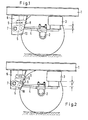
- each trailing arm on the console fixed to the arm is also height-adjustable in that the trailing arm is articulated on a swing arm which is pivotably mounted in the bracket and is short in relation to the trailing arm and is independent between each swing arm and the vehicle frame inflatable, additional air bellows is arranged by the suspension springs.
- a stop should be arranged in each additional air bellows, which determines the height of the articulation point for the trailing arm in normal driving operation.
- each trailing arm 4 is articulated on a rocker arm 5, which in turn is pivotally mounted on an axle 7 fastened in a bracket 6.
- An air bellows 8 is arranged between the rocker 5 and the vehicle frame 1 above the articulation point of the trailing arm 4.
- a further stop 10 for the rocker 5 in its lowest position is provided in the bracket 6 below the articulation point of the trailing arm 4.
- the device described is therefore suitable for changing the inclination of the vehicle frame 1 both in the direction of travel and transversely to the direction of travel.
Landscapes
- Engineering & Computer Science (AREA)
- Mechanical Engineering (AREA)
- Vehicle Body Suspensions (AREA)
Applications Claiming Priority (2)
| Application Number | Priority Date | Filing Date | Title |
|---|---|---|---|
| DE3416861A DE3416861C1 (de) | 1984-05-08 | 1984-05-08 | Hoehenverstellbare Luftfederung |
| DE3416861 | 1984-05-08 |
Publications (2)
| Publication Number | Publication Date |
|---|---|
| EP0166882A1 true EP0166882A1 (fr) | 1986-01-08 |
| EP0166882B1 EP0166882B1 (fr) | 1988-06-15 |
Family
ID=6235165
Family Applications (1)
| Application Number | Title | Priority Date | Filing Date |
|---|---|---|---|
| EP85104742A Expired EP0166882B1 (fr) | 1984-05-08 | 1985-04-19 | Suspension pneumatique réglable en hauteur |
Country Status (3)
| Country | Link |
|---|---|
| EP (1) | EP0166882B1 (fr) |
| DE (2) | DE3416861C1 (fr) |
| ES (1) | ES8607127A1 (fr) |
Cited By (5)
| Publication number | Priority date | Publication date | Assignee | Title |
|---|---|---|---|---|
| FR2678215A1 (fr) * | 1991-06-25 | 1992-12-31 | Renault | Train arriere pour vehicule routier. |
| EP0529544A1 (fr) * | 1991-08-22 | 1993-03-03 | ROCKINGER Spezialfabrik für Anhängerkupplungen GmbH & Co. | Semi-remorque avec dispositif de support actionné par un moteur |
| GB2322837A (en) * | 1996-02-06 | 1998-09-09 | Ernest Martin | Vehicle tilt system |
| WO1999004992A1 (fr) | 1997-07-24 | 1999-02-04 | Claas Saulgau Gmbh | Dispositif de reglage en hauteur et de suspension destine a une machine de mise en bottes des moissons |
| WO2020041847A1 (fr) * | 2018-08-31 | 2020-03-05 | Randon S/A Implementos E Participações | Bras de suspension pneumatique et procédé de montage |
Families Citing this family (1)
| Publication number | Priority date | Publication date | Assignee | Title |
|---|---|---|---|---|
| SE9002782D0 (sv) * | 1990-08-31 | 1990-08-31 | Anders Sjoelund | Hjulupphaengningsanordning |
Citations (8)
| Publication number | Priority date | Publication date | Assignee | Title |
|---|---|---|---|---|
| GB190429655A (en) * | 1904-12-31 | 1905-11-02 | George Johnston | Improvements in or connected with Buffer Devices for Vehicle Springs. |
| US2902291A (en) * | 1956-08-03 | 1959-09-01 | Canadian Car Company Ltd | Vehicle pneumatic suspension system |
| DE2038446A1 (de) * | 1969-08-07 | 1971-02-18 | Dunlop Co Ltd | Fahrzeugaufhaengung |
| DE1964365A1 (de) * | 1969-12-23 | 1971-07-01 | Daimler Benz Ag | Achsaufhaengung fuer Fahrzeuge |
| FR2068115A5 (fr) * | 1969-11-28 | 1971-08-20 | Bennes Marrel | |
| DE1780497A1 (de) * | 1968-09-21 | 1972-01-05 | Hanomag Henschel Fahrzeug | Achsanlenkung fuer zwei- oder mehrachsige Kraftfahrzeuge mit Luftfederung |
| US3794344A (en) * | 1972-07-10 | 1974-02-26 | J Raidel | Vehicle air suspension assembly |
| US4181323A (en) * | 1976-10-01 | 1980-01-01 | Raidel John E | Air spring and parallelogram suspension |
Family Cites Families (2)
| Publication number | Priority date | Publication date | Assignee | Title |
|---|---|---|---|---|
| DE1275888B (de) * | 1961-06-20 | 1968-08-22 | Daimler Benz Ag | Durch ein Pendel gesteuerte Hilfskraftvorrichtung zur Beeinflussung der Neigung eines Fahrzeuges, insbesondere Kraftfahrzeuges |
| FR1417275A (fr) * | 1964-09-29 | 1965-11-12 | Herwaythorn | Dispositif de suspension pneumatique de véhicule automobile |
-
1984
- 1984-05-08 DE DE3416861A patent/DE3416861C1/de not_active Expired
-
1985
- 1985-04-19 EP EP85104742A patent/EP0166882B1/fr not_active Expired
- 1985-04-19 DE DE8585104742T patent/DE3563333D1/de not_active Expired
- 1985-05-06 ES ES542856A patent/ES8607127A1/es not_active Expired
Patent Citations (8)
| Publication number | Priority date | Publication date | Assignee | Title |
|---|---|---|---|---|
| GB190429655A (en) * | 1904-12-31 | 1905-11-02 | George Johnston | Improvements in or connected with Buffer Devices for Vehicle Springs. |
| US2902291A (en) * | 1956-08-03 | 1959-09-01 | Canadian Car Company Ltd | Vehicle pneumatic suspension system |
| DE1780497A1 (de) * | 1968-09-21 | 1972-01-05 | Hanomag Henschel Fahrzeug | Achsanlenkung fuer zwei- oder mehrachsige Kraftfahrzeuge mit Luftfederung |
| DE2038446A1 (de) * | 1969-08-07 | 1971-02-18 | Dunlop Co Ltd | Fahrzeugaufhaengung |
| FR2068115A5 (fr) * | 1969-11-28 | 1971-08-20 | Bennes Marrel | |
| DE1964365A1 (de) * | 1969-12-23 | 1971-07-01 | Daimler Benz Ag | Achsaufhaengung fuer Fahrzeuge |
| US3794344A (en) * | 1972-07-10 | 1974-02-26 | J Raidel | Vehicle air suspension assembly |
| US4181323A (en) * | 1976-10-01 | 1980-01-01 | Raidel John E | Air spring and parallelogram suspension |
Cited By (6)
| Publication number | Priority date | Publication date | Assignee | Title |
|---|---|---|---|---|
| FR2678215A1 (fr) * | 1991-06-25 | 1992-12-31 | Renault | Train arriere pour vehicule routier. |
| EP0529544A1 (fr) * | 1991-08-22 | 1993-03-03 | ROCKINGER Spezialfabrik für Anhängerkupplungen GmbH & Co. | Semi-remorque avec dispositif de support actionné par un moteur |
| GB2322837A (en) * | 1996-02-06 | 1998-09-09 | Ernest Martin | Vehicle tilt system |
| GB2322837B (en) * | 1996-02-06 | 2000-06-14 | Ernest Martin | Vehicle tilt system |
| WO1999004992A1 (fr) | 1997-07-24 | 1999-02-04 | Claas Saulgau Gmbh | Dispositif de reglage en hauteur et de suspension destine a une machine de mise en bottes des moissons |
| WO2020041847A1 (fr) * | 2018-08-31 | 2020-03-05 | Randon S/A Implementos E Participações | Bras de suspension pneumatique et procédé de montage |
Also Published As
| Publication number | Publication date |
|---|---|
| DE3563333D1 (en) | 1988-07-21 |
| ES8607127A1 (es) | 1986-06-01 |
| EP0166882B1 (fr) | 1988-06-15 |
| ES542856A0 (es) | 1986-06-01 |
| DE3416861C1 (de) | 1985-12-19 |
Similar Documents
| Publication | Publication Date | Title |
|---|---|---|
| DE69112685T2 (de) | Blockierungsmechanismus für ein Fahrzeug. | |
| DE4027480C1 (fr) | ||
| DE19838328C1 (de) | Mehrspuriges Fahrzeug mit drei oder vier Rädern | |
| DE3302998C2 (de) | Radaufhängung für in den Fahrzeugkörper einschwenkbare Räder bzw. Radachsen | |
| DE3913697C2 (fr) | ||
| EP2246207B1 (fr) | Remorqueur d'aéroport doté d'une suspension à air | |
| EP0237619B1 (fr) | Suspension de roue pour superstructures de véhicule susceptibles d'étre abaissées, en particulier pour remorques, camions à traction-avant (bus-break), caravanes | |
| DE3013992A1 (de) | Lastfahrzeug mit radgestellen und hebezeug fuer ein raederpaar | |
| EP1123821B1 (fr) | Suspension à cinq bras pour une roue arrière de véhicule | |
| EP4338986B1 (fr) | Procédé pour accoupler une semi-remorque avec une semi-remorque ainsi que semi-remorque avec un semi-remorque et une semi-remorque | |
| EP0166882B1 (fr) | Suspension pneumatique réglable en hauteur | |
| DE4444115C2 (de) | Mehrspuriges Leichtfahrzeug | |
| DE69918012T2 (de) | Vorrichtung zum hochheben der achse eines fahrzeuges | |
| EP1021943B1 (fr) | Epandeur agricole | |
| DE69304236T2 (de) | Radaufhängungsvorrichtung für einen lenkbaren Vorderradsatz eines Nutzfahrzeuges | |
| DE1737686U (de) | Anordnung der federung, insbesondere der luftfederung fuer kraftfahrzeuge. | |
| DE19721130A1 (de) | Ladewagen mit zwei oder mehr Achsen | |
| DE8413888U1 (de) | Fahrzeugrahmen mit Neigungsausgleich | |
| DE1222389B (de) | Vorrichtung zur Abstuetzung der Last aus dem Aufbau und der Ladung von Lastkraftwagen bzw. der Aufliegerlast bei Sattelzuegen auf den Achsen bzw. Radfuehrungsorganen | |
| EP0827848B1 (fr) | Chassis pour véhicule à moteur ou remorques | |
| DE953228C (de) | Anordnung der Luftfederung bei Kraftfahrzeugen | |
| DE4007629A1 (de) | Luftfederachse | |
| DE2653278A1 (de) | Tieflader, insbesondere auflieger fuer den strassentransport von sperrigen lasten, z.b. von glasscheiben in aufrechter stellung | |
| DE3875237T2 (de) | Hintere kraftfahrzeugaufhaengung mit unabhaengigen raedern. | |
| DE4026791A1 (de) | Doppelachsaggregat fuer nutzfahrzeuge, insbesondere lastkraftwagen |
Legal Events
| Date | Code | Title | Description |
|---|---|---|---|
| PUAI | Public reference made under article 153(3) epc to a published international application that has entered the european phase |
Free format text: ORIGINAL CODE: 0009012 |
|
| AK | Designated contracting states |
Designated state(s): DE FR GB IT NL |
|
| 17P | Request for examination filed |
Effective date: 19851217 |
|
| 17Q | First examination report despatched |
Effective date: 19861219 |
|
| GRAA | (expected) grant |
Free format text: ORIGINAL CODE: 0009210 |
|
| AK | Designated contracting states |
Kind code of ref document: B1 Designated state(s): DE FR GB IT NL |
|
| ITF | It: translation for a ep patent filed | ||
| GBT | Gb: translation of ep patent filed (gb section 77(6)(a)/1977) | ||
| REF | Corresponds to: |
Ref document number: 3563333 Country of ref document: DE Date of ref document: 19880721 |
|
| ET | Fr: translation filed | ||
| PLBE | No opposition filed within time limit |
Free format text: ORIGINAL CODE: 0009261 |
|
| STAA | Information on the status of an ep patent application or granted ep patent |
Free format text: STATUS: NO OPPOSITION FILED WITHIN TIME LIMIT |
|
| 26N | No opposition filed | ||
| ITTA | It: last paid annual fee | ||
| PGFP | Annual fee paid to national office [announced via postgrant information from national office to epo] |
Ref country code: GB Payment date: 19930330 Year of fee payment: 9 |
|
| PGFP | Annual fee paid to national office [announced via postgrant information from national office to epo] |
Ref country code: FR Payment date: 19930417 Year of fee payment: 9 |
|
| PGFP | Annual fee paid to national office [announced via postgrant information from national office to epo] |
Ref country code: NL Payment date: 19930430 Year of fee payment: 9 |
|
| PGFP | Annual fee paid to national office [announced via postgrant information from national office to epo] |
Ref country code: DE Payment date: 19930611 Year of fee payment: 9 |
|
| PG25 | Lapsed in a contracting state [announced via postgrant information from national office to epo] |
Ref country code: GB Effective date: 19940419 |
|
| PG25 | Lapsed in a contracting state [announced via postgrant information from national office to epo] |
Ref country code: NL Effective date: 19941101 |
|
| GBPC | Gb: european patent ceased through non-payment of renewal fee |
Effective date: 19940419 |
|
| NLV4 | Nl: lapsed or anulled due to non-payment of the annual fee | ||
| PG25 | Lapsed in a contracting state [announced via postgrant information from national office to epo] |
Ref country code: FR Effective date: 19941229 |
|
| PG25 | Lapsed in a contracting state [announced via postgrant information from national office to epo] |
Ref country code: DE Effective date: 19950103 |
|
| REG | Reference to a national code |
Ref country code: FR Ref legal event code: ST |