EP0166941A2 - Procédé et commande prévus, entre autres, pour empêcher une influence dépendant de la charge sur l'état d'un commutateur - Google Patents
Procédé et commande prévus, entre autres, pour empêcher une influence dépendant de la charge sur l'état d'un commutateur Download PDFInfo
- Publication number
- EP0166941A2 EP0166941A2 EP85106266A EP85106266A EP0166941A2 EP 0166941 A2 EP0166941 A2 EP 0166941A2 EP 85106266 A EP85106266 A EP 85106266A EP 85106266 A EP85106266 A EP 85106266A EP 0166941 A2 EP0166941 A2 EP 0166941A2
- Authority
- EP
- European Patent Office
- Prior art keywords
- switch
- sensor
- voltage
- load
- signal
- Prior art date
- Legal status (The legal status is an assumption and is not a legal conclusion. Google has not performed a legal analysis and makes no representation as to the accuracy of the status listed.)
- Ceased
Links
Images


Classifications
-
- H—ELECTRICITY
- H03—ELECTRONIC CIRCUITRY
- H03K—PULSE TECHNIQUE
- H03K17/00—Electronic switching or gating, i.e. not by contact-making and –breaking
- H03K17/16—Modifications for eliminating interference voltages or currents
-
- H—ELECTRICITY
- H03—ELECTRONIC CIRCUITRY
- H03K—PULSE TECHNIQUE
- H03K17/00—Electronic switching or gating, i.e. not by contact-making and –breaking
- H03K17/51—Electronic switching or gating, i.e. not by contact-making and –breaking characterised by the components used
- H03K17/78—Electronic switching or gating, i.e. not by contact-making and –breaking characterised by the components used using opto-electronic devices, i.e. light-emitting and photoelectric devices electrically- or optically-coupled
- H03K17/79—Electronic switching or gating, i.e. not by contact-making and –breaking characterised by the components used using opto-electronic devices, i.e. light-emitting and photoelectric devices electrically- or optically-coupled controlling bipolar semiconductor switches with more than two PN-junctions, or more than three electrodes, or more than one electrode connected to the same conductivity region
-
- H—ELECTRICITY
- H05—ELECTRIC TECHNIQUES NOT OTHERWISE PROVIDED FOR
- H05B—ELECTRIC HEATING; ELECTRIC LIGHT SOURCES NOT OTHERWISE PROVIDED FOR; CIRCUIT ARRANGEMENTS FOR ELECTRIC LIGHT SOURCES, IN GENERAL
- H05B47/00—Circuit arrangements for operating light sources in general, i.e. where the type of light source is not relevant
- H05B47/10—Controlling the light source
- H05B47/105—Controlling the light source in response to determined parameters
- H05B47/11—Controlling the light source in response to determined parameters by determining the brightness or colour temperature of ambient light
-
- Y—GENERAL TAGGING OF NEW TECHNOLOGICAL DEVELOPMENTS; GENERAL TAGGING OF CROSS-SECTIONAL TECHNOLOGIES SPANNING OVER SEVERAL SECTIONS OF THE IPC; TECHNICAL SUBJECTS COVERED BY FORMER USPC CROSS-REFERENCE ART COLLECTIONS [XRACs] AND DIGESTS
- Y02—TECHNOLOGIES OR APPLICATIONS FOR MITIGATION OR ADAPTATION AGAINST CLIMATE CHANGE
- Y02B—CLIMATE CHANGE MITIGATION TECHNOLOGIES RELATED TO BUILDINGS, e.g. HOUSING, HOUSE APPLIANCES OR RELATED END-USER APPLICATIONS
- Y02B20/00—Energy efficient lighting technologies, e.g. halogen lamps or gas discharge lamps
- Y02B20/40—Control techniques providing energy savings, e.g. smart controller or presence detection
Definitions
- the present invention relates firstly to a control arrangement with a signal sensor and a switch for a load which is controlled by its output and which, when connected / disconnected, etc. Generates signals of the type detected by the sensor, a method for preventing load-related switch state influencing and secondly a method for electronically switching a load circuit by means of series switches, thirdly a method for electronically controlling a series load switch by means of a signal sensor for actuating the switch. Furthermore, the invention relates to an electronic control with a load switch and a sensor, which controls the switch with its output signal, an electronic control with a series switch for a load, and the combinations of the methods and controls mentioned.
- the latter When increasing the amplification downstream of the sensor, however, it must be taken into account that, depending on the controlled load, such as the illuminations mentioned, the latter also emit signals of the type detected by the sensor, here, for example, infrared radiation, so that with the aforementioned high amplification, the load radiation is fed back to the sensor can lead to uncontrolled system switching states, especially with operating transients.
- Such sensors are usually operated in such a way that they detect signal changes and non-stationary signal levels. Therefore, especially when connecting or. Shutdown of the resulting signals, if they are of the type detected by the sensor, dangerous in the above sense.
- a first signal is preferably set for a predetermined period of time when a signal change is detected and is re-established with the time period when further signal changes occur, the influence of the detected signal change on the first signal during a fall back of the first signal further specifiable period of time locks.
- the lighting should remain on for as long as someone is in the room, which leads to repeated signal changes due to detection. Only when no signal change is detected during the first of the specified periods of time is the lighting switched off and the sensor influence blocked for the further specifiable period of time. Thus, radiation changes that occur when the lighting is extinguished and are detected by the sensor have no effect on the switch state. With the latter type of control, all detected signal changes should lead to the load being applied. A signal change caused by this cannot influence the switch status anyway, but it is only necessary to ensure the switch-off behavior in the mentioned sense. However, there can certainly be cases, in particular if stationary signal values are detected by the sensor in a switching-effective manner, in which both load transients have to be deactivated with regard to the switch control.
- loads such as the above-mentioned illuminations operated on the AC circuit
- loads are controlled in series in the load circuit via manual switches without neutral conductor. If you want to switch from these manual switches to electronic switches, for example to control the loads mentioned via infrared sensors, the problem arises of how, in particular when the switch path is closed, the supply voltage for the electronics used is to be provided.
- Another object of the present invention is therefore to propose a method for electronically switching a load circuit by means of a series switch, in which this problem is solved. This is achieved by sequentially opening the switch intermittently when the load is applied and converting the voltage across the switch path to a DC voltage for supplying the switch control. If the load is operated on a DC circuit, for example, the DC voltage is above the latter when the switch path is open. When the switch path is closed, the voltage is above the load. Since an intended electronic circuit is to be provided over the switch section without further cabling, the load is disconnected from the operating network in certain subsequent periods by opening the switch section with a corresponding repetition frequency; a pulsating DC voltage is generated across the switch section that detects and smoothed as DC voltage for the supply of the switch control. Before the load is applied, the supply is ensured, since the switch is then opened anyway. The same principle is used for load circuits operated on alternating current by then phase-cutting the voltage across the switch path with the switch.
- the two problems often arise in combination, firstly, the one that increases the system sensitivity, such as by amplification kung increase, the load operating state can influence the switch state, and secondly, that such a circuit should be used as a series switch without additional wiring. Therefore, the method mentioned under third is formed according to the wording of claim 5. It is preferably assumed that, whether in direct current or alternating current operation, the voltage across the switch path with intermittent switch operation changes from that with the switch open, depending on whether the load is switched on or off.
- This change is detected on the direct voltage obtained directly from the voltage across the switch path, which is higher when the load is switched off than when it is switched on and thus also changes its value when changing from one operating state to another.
- This change indicates that, on the one hand, the load has assumed the new operating state and, on the other hand, any signals that have already been detected and are due to changes in the load state must be blocked by influencing the switch state.
- the DC voltage on the other hand, which is used to supply the control circuit, should be as independent as possible of the load operating state.
- the first DC voltage, the supply voltage, is therefore generated on an AC load circuit, preferably by voltage-limited AC / DC conversion of a signal, preferably tapped with an amplitude limitation, over the switch path.
- the electronic control with a load switch and a sensor, which with its output signal Activates the switch, as mentioned at the beginning, is made insensitive by signals generated in particular in switching transients of the load, of the type detected by the sensor, in that a blocking circuit is provided which, after at least one of the possible changes in state of the actuating signal, has the effect of the sensor for a predetermined period of time interrupts the switch and maintains the assumed switch state.
- the sensor output is preferably routed to a re-usable, monostable device with preferably adjustable time constants, and a further monostable device placed between the sensor and the switch when the device drops out is provided, preferably with likewise adjustable time constants, the output of this monostable device acting on a signal lock in the sensor switch signal path.
- a re-usable, monostable device with preferably adjustable time constants
- a further monostable device placed between the sensor and the switch when the device drops out is provided, preferably with likewise adjustable time constants, the output of this monostable device acting on a signal lock in the sensor switch signal path.
- Another object of the invention is to provide an electronic control system with a series switch for a load of the type mentioned at the outset, taking into account the above-mentioned problems for supplying the control system, which is achieved by training according to the wording of claim 10.
- the clock is preferably used for an AC load circuit circuit designed as a leading edge circuit for the voltage across the switch path.
- the supply voltage AC / DC converter is assigned a voltage limitation, such as a Zener diode circuit.
- the sensor is designed as an IR sensor and its output is routed to the switch via a comparator circuit with an adjustable reference voltage and / or with a reference voltage that is controlled by a second sensor adjustable reference voltage
- the response threshold of the control can be set and, on the other hand, that ambient conditions such as day / night differences can be detected by the second sensor and taken into account by correspondingly changing the reference voltage at the comparator mentioned.
- the sensor act on the switch via a comparator circuit, and that the blocking takes place by influencing its reference voltage.
- a sensor 1 shown as a converter, converts input signals S., such as infrared radiation, on the output side into an electrical signal S el , the latter, possibly amplified, of which is fed to a comparator unit 3, which, when the input signal S el is on this side of a signal pe is an output signal S 3 at a first signal value, otherwise at a second signal value, for example corresponding to logical signal levels '1' and '0'.
- a bistable unit 5 such as a flip-flop is set, with the falling edge of the signal S 3 is reset.
- the output Q of the bistable unit 5 controls a load switch S L in a circuit 7 for a load 9.
- the load switch S L remains closed during ⁇ 11 , corresponding to the control direction entered, for example, even if scatter signals S s fall on the sensor 1 when the load is thereby switched on.
- the Output signal Q triggered a second monostable unit 13 with a preferably adjustable pulse duration ⁇ 13 , which acts logically linked to the set input of unit 5 via an AND unit 15 with the output of comparator 3 with an output pulse drawn in polarity, the latter responding to rising signal edges. If the switch S L has thus been opened when the signal at the output Q has dropped, any rising signal edge at the set input S is blocked during the period ⁇ 13 : The switch S L remains blocked in the open position during this period.
- the unit 5 is not reset even after this, the switch S L remains closed. If, however, the signal S 3 is then at a low signal level, the signal at the reset input R drops when the output pulse of the unit 11 drops and the switch S L is opened. Analogous conditions occur with regard to the set input S: If the signal S 3 is at a low signal level after the time t has elapsed, the input S also remains low, the unit 5 is not set, the switch S L remains open. If, however, the signal S 3 is then at a high signal level, the unit 5 is set at the end of the output pulse of the unit 13. In this way, couplings to the sensor 1 provided, caused by the transient switching on and off of the load 9, are rendered inoperative.
- the electrical impulses of the one and / or the output side give different polarity as a function of signal changes at the sensor input. If such signal changes occur and thus electrical impulses at the electrical sensor output, this is interpreted, for example in the case of infrared sensors for room monitoring, in such a way that a radiation source to be detected, such as a living being, is in the monitored room. In such a state, ie signal changes occur in a predetermined minimum time sequence, a load such as lighting should occur. are otherwise switched off, the output of the sensor 1 is amplified and pulse-shaped at a unit 3a at most, switched to a resettable, monostable unit 17, with a preferably adjustable output pulse duration ⁇ 17 .
- Detected signal changes occur 1 / shorter than T17 at intervals, the switch-closing state at the output of the unit 17, for example, remains.
- the sensor registers both an increase and a decrease in the detected signal, which results in an increase in the information density.
- a monostable unit 19 which acts in analogy to the unit 13 of FIG. 1 and which emits a polar pulse, as shown, of the preferably adjustable time period z 19 .
- an AND unit 21 prevents signal changes which are effective per se and which are detected immediately after opening the switch S L and which can trigger the repeatable monostable unit 17 again.
- FIG. 3 a block diagram is shown to explain the structure of an electronically operated load switch in a load circuit 23.
- the load circuit 23 with a load 25, such as a lamp has, as usual, a switch path AB, which is conventionally closed or closed by a manually operated switch . is opened.
- the aim of the arrangement according to FIG. 3 is to have an electronically acting switch triggered, for example, by to operate a sensor 1 analogous to that shown in FIGS. 1 or 2 without having to provide any further electrical connections beyond the connections AB of the switch path.
- Circuit 23 is initially an AC circuit, such as a circuit operated with AC voltage.
- the load 25 switching signal such as a signal S1 at the output of the sensor 1
- the AC voltage lying across the connections AB is applied to a comparator unit 29 with a variable reference value at an adjustable source 31, and outputs the frequency and in accordance with the comparison of the network signal with the reference signal, output pulses S29, which intermittently close and open the electrically controllable load switch S L.
- the load 25 In the closed state, the load 25 is under voltage, in the open state the AC / DC converter 27, which now converts the cut AC voltage at the connections AB into a DC voltage for the electronics supply.
- the mains voltage is switched off to the comparator 29 in accordance with the sensor output signal S1, as shown schematically with the switch 33.
- circuit 23 is a DC circuit, in principle nothing changes in the functioning of the circuit shown.
- a clock generator 34 is provided which is triggered by the output signal of the sensor 1 and which controls the intermittent activation of the load switch S L.
- AC / DC converters for AC voltage operation for example, a rectifier / smoothing unit, so it will be for G facilitated voltage operation preferably a mean taking circuit as a low pass filter according to the selected cut-off frequency act.
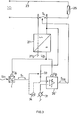
- FIG. 4 shows a preferred embodiment of a sensor-controlled electronic switch, arranged as a series switch in a load circuit, such as an infrared sensor-controlled switch for room lighting.
- the AC load circuit 35 with a load 37, shown here as a lamp, has a switch path AB, in which a manually operated switch is usually arranged.
- a resettable, monostable device 46 With those at the output of the comparator unit 43 appearing impulses is basically triggered a resettable, monostable device 46, the preferably adjustable time constant ⁇ 46 ⁇
- the output signal of the monostable device 46 is fed via a superposition unit 47 to a further comparator circuit 49, the latter of which is supplied with the switch path voltage U AB as a second input.
- the output of the comparator circuit 49 acts electrically controllable switch over the switch path AB, like a triac 51.
- the level of the output signal of the monostable device 46 is shifted in terms of DC at the superposition unit 47.
- the reference value for the comparator unit 49 is set on the adjustable source 53 in such a way that, with an output signal at the unit 46, correspondingly set unit, the switch voltage U AB reaches the reference value at a relatively small phase angle 1 and causes a signal change at the output of the unit 49 . If, on the other hand, the monostable device 46 is not set, the amplitude values of the voltage UAB do not reach the reference value. It goes without saying that, before the switch path voltage U AB is fed to the comparator unit 49, as shown in dashed lines, rectification, at most with attenuation k, can be carried out on an upstream unit 55.
- the control shown up to that point works as follows: If there is a signal change at the input of sensor 41 detected, the pulse S el appears at the sensor output. If the detected signal change is sufficiently large that the sensor output pulse exceeds the reference value U ref at the comparator unit 43, then a pulse U 43 ' also appears at its output, which sets the repeatable monostable device 46. This remains set as long as at time intervals which are smaller than its time constant ⁇ 46 , again signal changes of the specified magnitude are recorded at the sensor 41. By setting the device 46, the comparator unit 49 is set that reference signal which is already at a relatively small phase angle ⁇ of the switch path voltage U AB is reached, in this state, with the triac 51 not yet switched on, the entire mains voltage lies over the path AB.
- the voltage U AB reaches the reference value at the comparator circuit 49, whereupon its output ignites the triac 51. It is known that it remains ignited until the next current is zero-crossing, the mains voltage being above the load 37 during the ignited period of time and practically zero-voltage across the path AB. If the monostable device 46 remains set by a corresponding sequence of detected signal changes, there is thus a continuous phase gating of the voltage U AB , which then assumes the course represented by U ' Aß . In this operating state, ie with load 37 applied, the resulting DC output voltage would drop without additional measures in the case of an AC / DC conversion, as with converter 39.
Landscapes
- Electronic Switches (AREA)
- Circuit Arrangement For Electric Light Sources In General (AREA)
- Power Conversion In General (AREA)
Applications Claiming Priority (2)
| Application Number | Priority Date | Filing Date | Title |
|---|---|---|---|
| CH2726/84 | 1984-06-05 | ||
| CH272684 | 1984-06-05 |
Publications (2)
| Publication Number | Publication Date |
|---|---|
| EP0166941A2 true EP0166941A2 (fr) | 1986-01-08 |
| EP0166941A3 EP0166941A3 (fr) | 1987-10-21 |
Family
ID=4240224
Family Applications (1)
| Application Number | Title | Priority Date | Filing Date |
|---|---|---|---|
| EP85106266A Ceased EP0166941A3 (fr) | 1984-06-05 | 1985-05-22 | Procédé et commande prévus, entre autres, pour empêcher une influence dépendant de la charge sur l'état d'un commutateur |
Country Status (3)
| Country | Link |
|---|---|
| US (1) | US4656351A (fr) |
| EP (1) | EP0166941A3 (fr) |
| JP (1) | JPS612420A (fr) |
Cited By (1)
| Publication number | Priority date | Publication date | Assignee | Title |
|---|---|---|---|---|
| DE3828428C1 (en) * | 1988-08-22 | 1989-11-02 | Honeywell-Schild Ag, Biel, Ch | Voltage supply for proximity switches |
Families Citing this family (1)
| Publication number | Priority date | Publication date | Assignee | Title |
|---|---|---|---|---|
| CN103885354A (zh) * | 2012-12-22 | 2014-06-25 | 鸿富锦精密工业(深圳)有限公司 | 无线开关电路 |
Family Cites Families (4)
| Publication number | Priority date | Publication date | Assignee | Title |
|---|---|---|---|---|
| DE2547514A1 (de) * | 1975-10-23 | 1977-04-28 | Joachim Reich | Daemmerungsschalter |
| DE2751917C2 (de) * | 1977-11-21 | 1984-10-18 | Preh, Elektrofeinmechanische Werke Jakob Preh Nachf. Gmbh & Co, 8740 Bad Neustadt | Elektronische Schaltung zur drahtlosen, fernbedienbaren Helligkeitssteuerung von Leuchtquellen |
| SE428250B (sv) * | 1979-05-31 | 1983-06-13 | Bert Jonsson | Fotoelektrisk anordning for avkenning av foremal |
| US4346427A (en) * | 1979-06-29 | 1982-08-24 | Robert Rothenhaus | Control device responsive to infrared radiation |
-
1984
- 1984-12-14 US US06/681,953 patent/US4656351A/en not_active Expired - Fee Related
-
1985
- 1985-05-22 EP EP85106266A patent/EP0166941A3/fr not_active Ceased
- 1985-06-05 JP JP60122376A patent/JPS612420A/ja active Pending
Cited By (1)
| Publication number | Priority date | Publication date | Assignee | Title |
|---|---|---|---|---|
| DE3828428C1 (en) * | 1988-08-22 | 1989-11-02 | Honeywell-Schild Ag, Biel, Ch | Voltage supply for proximity switches |
Also Published As
| Publication number | Publication date |
|---|---|
| US4656351A (en) | 1987-04-07 |
| JPS612420A (ja) | 1986-01-08 |
| EP0166941A3 (fr) | 1987-10-21 |
Similar Documents
| Publication | Publication Date | Title |
|---|---|---|
| DE3618693C2 (fr) | ||
| EP0985881B1 (fr) | Système de surveillance de flammes | |
| DE3881088T2 (de) | Leistungsversorgung mit automatischer Spannungsanpassung. | |
| EP1247431B1 (fr) | Dispositif et procede pour commander des moyens d'exploitation pour au moins un moyen d'eclairage electrique | |
| DE19748430A1 (de) | Schaltung und Verfahren zum Verhindern eines Lichtbogens bei einem mechanischen Schalter | |
| DE102006024430A1 (de) | Zweikreisiger Wandschalter-Anwesenheits-Sensor und Verfahren für dessen Betrieb | |
| DE3533523C2 (fr) | ||
| EP3183584B1 (fr) | Dispositif de détection d'une tension d'alimentation et procédé de détection d'une tension d'alimentation | |
| DE3603568A1 (de) | Flammen-detektor | |
| DE3931038C2 (fr) | ||
| DE3320975A1 (de) | Elektronisches, vorzugsweise beruehrungslos arbeitendes schaltgeraet | |
| EP0166941A2 (fr) | Procédé et commande prévus, entre autres, pour empêcher une influence dépendant de la charge sur l'état d'un commutateur | |
| EP1121001B1 (fr) | Commutateur électronique | |
| DE10200905B4 (de) | Photoelektrischer Schalter | |
| CH646288A5 (en) | Circuit arrangement for a proximity switch, particularly for sanitary use | |
| CH665297A5 (de) | Anordnung zum ueberwachen von signalen an ausgaengen von steuerschaltungen in verkehrssteuersystemen. | |
| EP2702838B1 (fr) | Ballast électronique pour un appareil d'éclairage | |
| DE2736783C3 (de) | Grenzwert-Meldevorrichtung für Wechselsignale | |
| DE3214669C2 (de) | Anordnung zum Betrieb von Entladungslampen | |
| DE2426318A1 (de) | Stoersichere verzoegerungsschaltung | |
| DE9410088U1 (de) | Steuergerät für wenigstens eine Lichtquelle | |
| DE3511207C2 (fr) | ||
| DE2809993B2 (de) | Flammenwächterschaltung zur Überwachung einer Brennerflamme | |
| DE4214300C1 (en) | Hysteresis reduction method for inductive or capacitive proximity switch - disconnects operating voltage when detected object lies within response range of switch sensor to prevent hysteresis | |
| EP0062288B1 (fr) | Barrière lumineuse à impulsions à connecter directement à une source de courant alternatif |
Legal Events
| Date | Code | Title | Description |
|---|---|---|---|
| PUAI | Public reference made under article 153(3) epc to a published international application that has entered the european phase |
Free format text: ORIGINAL CODE: 0009012 |
|
| AK | Designated contracting states |
Designated state(s): AT BE CH DE FR GB IT LI LU NL SE |
|
| 17P | Request for examination filed |
Effective date: 19860705 |
|
| PUAL | Search report despatched |
Free format text: ORIGINAL CODE: 0009013 |
|
| AK | Designated contracting states |
Kind code of ref document: A3 Designated state(s): AT BE CH DE FR GB IT LI LU NL SE |
|
| 17Q | First examination report despatched |
Effective date: 19890307 |
|
| STAA | Information on the status of an ep patent application or granted ep patent |
Free format text: STATUS: THE APPLICATION HAS BEEN REFUSED |
|
| 18R | Application refused |
Effective date: 19921106 |
|
| APAF | Appeal reference modified |
Free format text: ORIGINAL CODE: EPIDOSCREFNE |
|
| RIN1 | Information on inventor provided before grant (corrected) |
Inventor name: ZUEBLIN, MARCEL Inventor name: REICHLIN, ANTON |