EP0166965A1 - Alimentation de puissance haute tension à haute fréquence - Google Patents
Alimentation de puissance haute tension à haute fréquence Download PDFInfo
- Publication number
- EP0166965A1 EP0166965A1 EP85106599A EP85106599A EP0166965A1 EP 0166965 A1 EP0166965 A1 EP 0166965A1 EP 85106599 A EP85106599 A EP 85106599A EP 85106599 A EP85106599 A EP 85106599A EP 0166965 A1 EP0166965 A1 EP 0166965A1
- Authority
- EP
- European Patent Office
- Prior art keywords
- voltage
- voltage power
- power supply
- frequency
- load
- Prior art date
- Legal status (The legal status is an assumption and is not a legal conclusion. Google has not performed a legal analysis and makes no representation as to the accuracy of the status listed.)
- Withdrawn
Links
- 239000003990 capacitor Substances 0.000 claims abstract description 27
- 230000010355 oscillation Effects 0.000 claims abstract description 10
- 238000004804 winding Methods 0.000 claims description 23
- 238000010304 firing Methods 0.000 claims description 4
- 230000006698 induction Effects 0.000 claims description 4
- WABPQHHGFIMREM-UHFFFAOYSA-N lead(0) Chemical compound [Pb] WABPQHHGFIMREM-UHFFFAOYSA-N 0.000 description 12
- XUIMIQQOPSSXEZ-UHFFFAOYSA-N Silicon Chemical compound [Si] XUIMIQQOPSSXEZ-UHFFFAOYSA-N 0.000 description 9
- 229910052710 silicon Inorganic materials 0.000 description 9
- 239000010703 silicon Substances 0.000 description 9
- 239000000428 dust Substances 0.000 description 7
- 238000000034 method Methods 0.000 description 6
- 230000008859 change Effects 0.000 description 4
- 238000010586 diagram Methods 0.000 description 4
- 150000002500 ions Chemical class 0.000 description 4
- 230000001052 transient effect Effects 0.000 description 4
- 241000149947 Coronarchaica corona Species 0.000 description 2
- 238000010276 construction Methods 0.000 description 2
- 230000001276 controlling effect Effects 0.000 description 2
- 238000001514 detection method Methods 0.000 description 2
- 238000009413 insulation Methods 0.000 description 2
- 238000004519 manufacturing process Methods 0.000 description 2
- 239000002245 particle Substances 0.000 description 2
- 230000002265 prevention Effects 0.000 description 2
- 230000008569 process Effects 0.000 description 2
- 230000009467 reduction Effects 0.000 description 2
- 230000002441 reversible effect Effects 0.000 description 2
- CBENFWSGALASAD-UHFFFAOYSA-N Ozone Chemical compound [O-][O+]=O CBENFWSGALASAD-UHFFFAOYSA-N 0.000 description 1
- HCBIBCJNVBAKAB-UHFFFAOYSA-N Procaine hydrochloride Chemical compound Cl.CCN(CC)CCOC(=O)C1=CC=C(N)C=C1 HCBIBCJNVBAKAB-UHFFFAOYSA-N 0.000 description 1
- 241000289690 Xenarthra Species 0.000 description 1
- PNEYBMLMFCGWSK-UHFFFAOYSA-N aluminium oxide Inorganic materials [O-2].[O-2].[O-2].[Al+3].[Al+3] PNEYBMLMFCGWSK-UHFFFAOYSA-N 0.000 description 1
- 238000006243 chemical reaction Methods 0.000 description 1
- 230000003111 delayed effect Effects 0.000 description 1
- 238000007599 discharging Methods 0.000 description 1
- 230000000694 effects Effects 0.000 description 1
- 230000005684 electric field Effects 0.000 description 1
- 238000011156 evaluation Methods 0.000 description 1
- 230000005284 excitation Effects 0.000 description 1
- 238000001914 filtration Methods 0.000 description 1
- 239000011521 glass Substances 0.000 description 1
- 239000011229 interlayer Substances 0.000 description 1
- 230000004048 modification Effects 0.000 description 1
- 238000012986 modification Methods 0.000 description 1
- 230000003647 oxidation Effects 0.000 description 1
- 238000007254 oxidation reaction Methods 0.000 description 1
- 230000001681 protective effect Effects 0.000 description 1
- 239000002994 raw material Substances 0.000 description 1
- 230000001105 regulatory effect Effects 0.000 description 1
- 230000004044 response Effects 0.000 description 1
- 239000000126 substance Substances 0.000 description 1
Images


Classifications
-
- H—ELECTRICITY
- H03—ELECTRONIC CIRCUITRY
- H03K—PULSE TECHNIQUE
- H03K3/00—Circuits for generating electric pulses; Monostable, bistable or multistable circuits
- H03K3/02—Generators characterised by the type of circuit or by the means used for producing pulses
- H03K3/53—Generators characterised by the type of circuit or by the means used for producing pulses by the use of an energy-accumulating element discharged through the load by a switching device controlled by an external signal and not incorporating positive feedback
- H03K3/57—Generators characterised by the type of circuit or by the means used for producing pulses by the use of an energy-accumulating element discharged through the load by a switching device controlled by an external signal and not incorporating positive feedback the switching device being a semiconductor device
-
- H—ELECTRICITY
- H02—GENERATION; CONVERSION OR DISTRIBUTION OF ELECTRIC POWER
- H02M—APPARATUS FOR CONVERSION BETWEEN AC AND AC, BETWEEN AC AND DC, OR BETWEEN DC AND DC, AND FOR USE WITH MAINS OR SIMILAR POWER SUPPLY SYSTEMS; CONVERSION OF DC OR AC INPUT POWER INTO SURGE OUTPUT POWER; CONTROL OR REGULATION THEREOF
- H02M7/00—Conversion of AC power input into DC power output; Conversion of DC power input into AC power output
- H02M7/42—Conversion of DC power input into AC power output without possibility of reversal
- H02M7/44—Conversion of DC power input into AC power output without possibility of reversal by static converters
- H02M7/48—Conversion of DC power input into AC power output without possibility of reversal by static converters using discharge tubes with control electrode or semiconductor devices with control electrode
- H02M7/505—Conversion of DC power input into AC power output without possibility of reversal by static converters using discharge tubes with control electrode or semiconductor devices with control electrode using devices of a thyratron or thyristor type requiring extinguishing means
- H02M7/515—Conversion of DC power input into AC power output without possibility of reversal by static converters using discharge tubes with control electrode or semiconductor devices with control electrode using devices of a thyratron or thyristor type requiring extinguishing means using semiconductor devices only
- H02M7/523—Conversion of DC power input into AC power output without possibility of reversal by static converters using discharge tubes with control electrode or semiconductor devices with control electrode using devices of a thyratron or thyristor type requiring extinguishing means using semiconductor devices only with LC-resonance circuit in the main circuit
- H02M7/5233—Conversion of DC power input into AC power output without possibility of reversal by static converters using discharge tubes with control electrode or semiconductor devices with control electrode using devices of a thyratron or thyristor type requiring extinguishing means using semiconductor devices only with LC-resonance circuit in the main circuit the commutation elements being in a push-pull arrangement
- H02M7/5236—Conversion of DC power input into AC power output without possibility of reversal by static converters using discharge tubes with control electrode or semiconductor devices with control electrode using devices of a thyratron or thyristor type requiring extinguishing means using semiconductor devices only with LC-resonance circuit in the main circuit the commutation elements being in a push-pull arrangement in a series push-pull arrangement
Definitions
- the present invention relates to a less expensive high-frequency high-voltage power supply for efficiently feeding a high-frequency high-voltage to a large-sized capacitive load such as an ozonizer, an A.C. corona type ionizer, an electric dust collector, etc.
- a high-frequency primary power supply having a low voltage and a high power is constructed by making use of transistors, thyristors, thyratrons, transmitter tubes, etc.
- the output of the primary power supply is fed to a primary side (low voltage side) of a high-frequency high-voltage transformer, and the output on the secondary side (high voltage side) of the transformer is fed to an object load.
- the load circuit becomes nonlinear type, and hence, not only compensation for the capacitance C L in a strict mean becomes impossible, but also even if an inductance L, which can approximately compensate for the capacitance C L at a certain operating point with regard to the current, voltage and frequency, is inserted, the compensation for the capacitance C L would become ineffective in response to slight change of the operating point.
- the compensation for the load capacitance by means of the parallel inductance is also difficult, hence sufficient reduction of the required capacity [KVA] of the high-frequency primary power supply and the high-frequency high-voltage transformer cannot be achieved either, and thus one cannot overcome the shortcoming that solution for the problems of high cost and large loss is difficult.
- the aforementioned object can be achieved by generating a high-frequency high-voltage on the high voltage side with the aid of L-C oscillation without employing the high-frequency primary power supply and the high-frequency high-voltage transformer which would cause a low efficiency and a high cost.
- the high-frequency high-voltage power supply according to the present invention is characterized in that it comprises two D.C. high-voltage power supplies A and B, among the output terminals of the respective D.C. high-voltage power supplies a negative output terminal of one D.C. high-voltage power supply A and a positive output terminal of the other D.C. high-voltage power supply B are connected with each other and then connected to one of high-frequency high-voltage output terminals, tank capacitors respectively having a sufficiently large electrostatic capacitance Co as compared to an electrostatic capacitance C of a load are connected between the output terminals of the respective D.C.
- said high-frequency high-voltage power supply also comprises a first combination of a first thyristor and a first rectifier connected in an anti-parallel relationship to each other and having one end connected to a positive output terminal of said one D.C. high-voltage power supply A and a second combination of a second thyristor and a second rectifier connected in an anti- parallel relationship to each other and having one end connected to a negative output terminal of said the other D.C. high-voltage power supply B, the direction of conduction of said first thyristor being such that the anode of said first thyristor is connected to the positive output terminal of said one D.C.
- said.high-frequency high-voltage power supply further comprises a control device for feeding current pulses having a predetermined frequency alternately to the gates of the respective thyristors to turn on these thyristors alternately; whereby when a capacitive load is connected between said high-frequency high-voltage output terminals, said respective thyristors are alternately-turned on by feeding current pulses
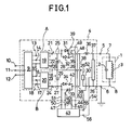
- a region 1 encircled by a dotted line represents an equivalant circuit of a capacitive load which consists of a parallel connection of a capacitor 2 having an electrostatic capacitance C F and a resistor 3 having a high resistance R [ ⁇ ].
- Another region 4 that is also encircled by a dotted line represents a high-frequency high-voltage power supply according to the present invention, and output terminals 5 and 6 of the power supply 4 are connected to the opposite ends of the above-described capacitive load 1 through lead wires 7 and 8, respectively.
- either one of the terminals 5 and 6 could be grounded, and in the illustrated example, the terminal 6 is grounded.
- Reference numeral 9 designates a high-voltage transformer of the commercial frequency having two independent secondary windings for which any one of a single-phase transformer, a three-phase transformer and a multiphase transformer is available, and in the illiustrated example, a three-phase transformer is employed.
- Primary terminals 10, 11 and 12 of the transformer are connected to a three-phase power supply of the commercial frequency, and output terminals 13, 14 and 15, and 16,17 and 18, respectively, of the two secondary windings are connected to input sides of three-phase rectifiers 19 and 20, respectively.
- the terminals 21 and 23 are positive, while the terminals 22 and 24 are negative, and the terminals 22 and 23 are jointly connected.
- the output terminals 21 and 22 are connected via lead wires 25 and 26 to a tank capacitor 28 having a sufficiently large electrostatic capacitance Co as compared to the load capacitance C (more than several times as large as the latter), while the output terminals 23 and 24 are connected via lead wires 26 and 27 to a tank capacitor 29 having a likewise sufficiently large electrostatic capacitance Co as compared to the load capacitance C L , to charge these tank capacitors 28 and 29 with the illustrated polarities.
- the lead wire 26 is connected via a current detector 30 to the output terminal 6 of the high-frequency high-voltage power supply 4, and then it is grounded.
- Reference numerals 31 and 32 and reference numerals 33 and 34 designate pairs of a thyristor and a silicon rectifier connected in an antiparallel relationship with the illustrated directions of conduction.
- One ends of the thyristor 31 and the silicon rectifier 32 are connected via the lead wire 25 to a positive high-voltage end of the tank capacitor 28, while the other ends ofthe"thyristor 31 and the silicon rectifier 32 are connected via a lead wire 35, a resonant inductance 36 and a lead wire 37 to the output terminal 5 of the high-frequency high-voltage power supply 4.
- One ends of the thyristor 33 and the silicon rectifiier 34 are connected via the lead wire 27 to a negative high-voltage end of the tank capacitor 29, while the other ends of the thyristor 33 and the silicon rectifier 34 are connected via a lead wire 38, the above-mentioned resonant inductance 36 and the lead wire 37 to the same output terminal 5.
- Reference numerals 39 and 40 designate gate terminals for turning on the thyristors 31 and 33, respectively, and reference numerals 41 and 42 designate small turn-off inductances inserted in series with the silicon rectifiers 32 and 34, respectively, for ensuring turn-off of the thyristors 31 and 33, respectively.
- Reference numeral 43 designates a thyristor control device for applying control signals to the thyristors 31 and 33, respectively, for making these thyristors alternately conduct at a predetermined frequency f, which control device feeds current pulses alternately from its output terminals 44 and 45 through lead wires 48 and 49 between the gate terminal 39 and the cathode of the thyristor 31 and from its output terminals 46 and 47 through lead wires 50 and 51 between the gate terminal 40 and the cathode of the thyristor 33.
- control device 43 performs protective control such as prevention of short-circuiting of the outputs of the three-phase rectifiers 19 and 20 through the lead wire 38 caused by simultaneous firing of the thyristors 31 and 32 and interruption of the output upon an accident of short-circuiting of the load 1, as will be described later.
- the residual voltage Vr is generated by electric power consumption in the resistive component R of the load and the other circuit loss, and the larger the loss is, the larger becomes the residual voltage Vr.
- a curren pulse i 2 as shown in Fig. 3 is fed as a gate signal from the control device 43 through the terminals 46 and 47 and the lead wires 50 and 51 between the gate terminal 40 and the cathode of the thyristor 33 at a time point t 1 that is delayed by a period T 1 from the time point t 0 , then the thysistor 33 is immediately turned on, and now the charged voltage -V 0 on the tank capacitor 29 is applied to the load 1 via the resonant inductance 36 and the output terminals 5 and 6, hence transient oscillation in the series circuit C 0 - L 0 - C L consisting of the capacitance Co [F] of the tank capacitor 29, the resonant inductance L 0 [H] and the load capacitance C L [F] is commenced.
- a high-frequency high voltage V(t) having a cycle period of that is equal to the time interval of t 0 t 2 as shown in Fig. 4 can be applied to the load, and in association therewith a high-frequency current likewise having a cycle period of T 2 can be fed to the load.
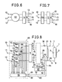
- the peak volue V of the above-mentioned load voltage V(t) can be arbitrarily regulated by varying the primary voltage of the transformer 9 to thereby change the charged voltage v 0 of the tank capacitors 28 and 29, through the method of switching taps of the primary winding or the secondary winding of the transformer 9, inserting a three-phase induction regulator 63 between the transformer 9 and the terminals 10, 11 and 12 as shown in Fig. 6, inserting a three-phase saturable reactor 64 between the transformer 9 and the terminals 10, 11 and 12 as shown in Fig, 7, or inserting any appropriate voltage regulator such as a three-phase anti-parallel thyristor firing pfiace control type voltage regulator 65 or the like as shown in Fig. 8.
- the voltage regulator 65 comprises anti-parallel connections of thyristors 66 and 67, 68 and 69, and 70 and 71 which are connected respectively in the three lead wires for connecting the primary terminals of the transformer 9 with the three-phase A.C. terminals 10, 11 and 12, respectively, and a primary control device 78 for feeding turn-on current pulses to the gates 72-77 of these thyristors 66 ⁇ 71 at appropriate phases of the three-phase A.C. voltage, and it can arbitrarily control the input and output voltages of the transformer 3 and accordingly the output D.C. high voltage Vo of the three-phase rectifiers 19 and 20 not shown in Fig. 8(shown in Fig. 1) by controlling the firing phases in the both positive and negative cycles of the respective phase voltages for turning on the respective thyristors.
- modification could be made such that the current detection signal from the current detector 30 and the voltage detection signal from the voltage detector 52 are fed to the primary side control device 78 via lead wires 79 and 80 and input terminals 81 and 82 to make this control device 78 achieve the above-described determination for accidents, thus the power supply is interrupted on the primary side of the transformer 9 by stopping the feed of the current pulses from the control device 78 to the gates 72-77 of the thyristors 66-71, thereby prevention of a serious accident can be prevented, and also the control device 78 is made to effect display of the accident.
- the output frequency f of the power supply according to the present invention is given by the following equation:
- This frequency f can be varied by varying the frequency of the current pulses fed from the control device 43 to the gates 39 and 40 of the thyristors 31 and 33 to thereby change the cycle period T 1 .
- the cycle period T 1 has the following lower limit: Accordingly, the highest (maximum) frequency f max is given by the following equation: Therefore, in order to increase the maximum frequency f max it is necessary to reduce the inductance value L of the resonant inductance to a small value.
- the means for applying positive and negative D.C. high voltages to the tank capacitors is not limited to the example shown in Fig. 1, but as a matter of course, any type of D.C. power supplies could be employed provided that they are two D .C. high-voltage power supplies or two variable-voltage D.C. high-voltage power supplies.
- any type of rectifier such as a single-phase half-wave rectifier, a single-phase full-wave transformer, a bridge-connection single-phase full-wave rectifier, etc.
- variable-voltage D,C. high-voltage power supply one may use switching of taps on the primary side or the secondary side of the high-voltage transformer 9, or else on the primary side of a single-phase or three-phase high-voltage transformer, one may use a single-phase or three-phase induction regulator, an antotransformer, a saturable reactor type voltage regulator in which a primary current of the high-voltage transformer is varied by means of a saturable reactor, an anti- parallel connection thyristor phase-control type voltage regulator in which thyristors connected in an anti-parallel relationship are inserted and the primary current of the high-voltage transformer is varied by controlling the turn-on phases of the thyristors, or the like.
- Fig.9 shows another prefersed embodiment of the present invention adapted for the case where the load 1 has a relatively small capacitance (Simce the construction of the high-fregnency high-voltage power supply 4 is similar to that shown in Fig. 1 , further illustration thereof has been omitted.)
- this enbodiment aims at raising an electric power efficiency by making use of thyristors having a relatively small output power and by assuring to obtain a necessary high voltage with the aid of a step-up transformer connected between the output of the thyristors and the load 1. More particularly, output terminals 5 and 6 of the high-frequency high-voltage power supply 4 are connected to the load 1 by the intermediary of a step-up transformer 83.
- Fig. 10 shows still another prefersed embodiment of the present invention adepted for the case where the load 1 has a relatively small capacitance.
- connection between the three-phase rectifier 19 and the tank capacitor 28 is identical to that shown in Fig. 1, the polarity of the connection between the three-phase rectifier 20 and the tank capacitor 29 is reversed, resonant inductances 36 and 36' are provided in the respective thyristor circuits, output terminals 5 and 5' of high-frequency high voltages and another output terminal 6 to which negative output terminals 22 and 23 of the D.C. high-voltage power supplies A and B are connected in common, are connected respectively to the opposite ends and a center tap of a primary winding of a step-up transformer 84, and the load 1 is connected to a secondary winding of the step-up transformer 84.
- the novel high-frequency high-voltage power supply according to the present invention is generally available for any load so long as the load is a capacitive load.
- the power supply can be used for a high-frequency corona type ionizer, in which a corona discharge electrode and a non-corona opposite electrode, or corona discharge electrodes themselves are opposed to each other as insulated from each other, a high-frequency high voltage is applied between these electrode to generate high-frequency A.C. corona discharge, resulting in production of plasma consisting of ions of the both positive and negative polarities to be used for removing electric charge from a body or charging a body by extracting positive or nagative monopolar ions from that plasma with the aid of an applied D.C.
- the high-frequency high voltage power supply according to the present invention can be used for discharge-chemical apparatuses, in which production of ozone, oxidation of NO or S0 2 , and other various discharge-chemical reactions are induced by passing a raw material gas through a discharge z'one of high-frequency corona discharge that is generated by means of the above-described electrode construction, high-frequency silent discharge that is generated by applying a high-frequency high voltage between opposed electrodes which are insulated from each other via a dielectric and a relatively small gap of gas space, high-frequency creaping discharge that is generated by applying a high-frequency high voltage between a corona discharge electrode disposed on a front surface of a dielectric such as glass or high-purity alumina and a broad two-dimensional induction electrode disposed on the back surface of the same dielectric or within the same dielectric, or the like.
- a plurality of such ionizers in combination can be used as the so-called high-frequency excitation type boxer charger, in which a charging alternating voltage of sinusoidal or rectangular waveform at a relatively low frequency (50-500 Hz) is applied between two adjacent ionizers among the plurality of ionizers in combination, a high-frequency high voltage is applied between the opposed electrodes of one of the adjacent ionizers only when the one ionizer takes a predetermined positive or negateve polarity with respect to the other of the adjacent ionizers to generate plasma (the high-frequency high voltage being not applied to the other ionizer), the above-described application of the high-frequency high voltage is alternately repeated for the adjacent ionizers in every half period of the aforementioned charging alternating voltage, thereby ions of the above-referred predetermined polarity are extracted
- the high-frequency power supply according to the present invention can be applied arbitrarily to every application other then the above-described ones, which necessitates to apply a high-frequency high voltage to a capacitive load.
Landscapes
- Engineering & Computer Science (AREA)
- Power Engineering (AREA)
- Generation Of Surge Voltage And Current (AREA)
- Ac-Ac Conversion (AREA)
Applications Claiming Priority (2)
| Application Number | Priority Date | Filing Date | Title |
|---|---|---|---|
| JP114350/84 | 1984-06-04 | ||
| JP59114350A JPH0720379B2 (ja) | 1984-06-04 | 1984-06-04 | 高周波高圧電源 |
Publications (1)
| Publication Number | Publication Date |
|---|---|
| EP0166965A1 true EP0166965A1 (fr) | 1986-01-08 |
Family
ID=14635547
Family Applications (1)
| Application Number | Title | Priority Date | Filing Date |
|---|---|---|---|
| EP85106599A Withdrawn EP0166965A1 (fr) | 1984-06-04 | 1985-05-29 | Alimentation de puissance haute tension à haute fréquence |
Country Status (3)
| Country | Link |
|---|---|
| US (1) | US4644457A (fr) |
| EP (1) | EP0166965A1 (fr) |
| JP (1) | JPH0720379B2 (fr) |
Cited By (2)
| Publication number | Priority date | Publication date | Assignee | Title |
|---|---|---|---|---|
| CN104393766A (zh) * | 2014-12-16 | 2015-03-04 | 福建龙净环保股份有限公司 | 一种除尘用叠加式电源控制系统 |
| CN105978392A (zh) * | 2016-06-07 | 2016-09-28 | 张家口市杰星电子科技有限公司 | 一种厨房油烟净化器专用智能高压电源 |
Families Citing this family (6)
| Publication number | Priority date | Publication date | Assignee | Title |
|---|---|---|---|---|
| KR20060010230A (ko) * | 2004-07-27 | 2006-02-02 | 삼성전자주식회사 | 이온발생장치 |
| US20080097723A1 (en) * | 2006-09-11 | 2008-04-24 | Universidad Tecnica Federico Santa Maria | Intelligent monitoring system and method for mill drives in mineral grinding processes |
| CN103944389B (zh) * | 2014-04-04 | 2016-02-10 | 南京国电环保科技有限公司 | 一种新型的谐振变换器 |
| US9917463B2 (en) * | 2015-09-25 | 2018-03-13 | General Electric Company | System and method for discharging a thyristor-switched capacitor |
| CN106655870B (zh) * | 2016-11-01 | 2018-12-28 | 南京航空航天大学 | 一种脉冲电压优化的脉冲电源电路 |
| CN108718158A (zh) * | 2018-07-15 | 2018-10-30 | 浙江大维高新技术股份有限公司 | 脉冲电晕放电等离子体电源倍频电路 |
Citations (5)
| Publication number | Priority date | Publication date | Assignee | Title |
|---|---|---|---|---|
| US3953779A (en) * | 1974-05-30 | 1976-04-27 | Francisc Carol Schwarz | Electronic control system for efficient transfer of power through resonant circuits |
| FR2415412A1 (fr) * | 1978-01-20 | 1979-08-17 | Siemens Ag | Generateur pour appareil de radiodiagnostic comportant un onduleur alimentant son transformateur a haute tension |
| GB2045019A (en) * | 1979-03-06 | 1980-10-22 | Siemens Ag | High voltage generator |
| FR2453533A1 (fr) * | 1979-04-04 | 1980-10-31 | Wabco Westinghouse Spa | Convertisseur electrique statique autoresonant |
| EP0034075A2 (fr) * | 1980-01-24 | 1981-08-19 | Merlin Gerin | Dispositif d'alimentation statique d'un électrofiltre de dépoussiérage électrostatique |
Family Cites Families (10)
| Publication number | Priority date | Publication date | Assignee | Title |
|---|---|---|---|---|
| US3569819A (en) * | 1969-01-16 | 1971-03-09 | Gen Electric | Recovery system for short circuits through switching devices in power circuits |
| DE2123912A1 (de) * | 1971-05-14 | 1972-11-23 | Multiblitz Dr.-Ing. D.A. Mannesmann Gmbh & Co Kg, 5050 Porz | Schaltungsanordnung zum Aufladen eines Speicherkondensators |
| JPS5456135A (en) * | 1977-10-13 | 1979-05-04 | Ishikawajima Harima Heavy Ind | High voltage pulse generator |
| JPS5495946A (en) * | 1978-01-13 | 1979-07-28 | Nichicon Capacitor Ltd | Capacitorrtype welder |
| US4180853A (en) * | 1978-08-23 | 1979-12-25 | United Technologies Corporation | Two-stage commutation circuit for an inverter |
| US4173779A (en) * | 1978-12-08 | 1979-11-06 | Westinghouse Electric Corp. | Single-pole commutation circuit |
| US4255783A (en) * | 1979-05-30 | 1981-03-10 | United Technologies Corporation | Selective commutation circuit for an inverter |
| US4286317A (en) * | 1979-08-16 | 1981-08-25 | Bbc Brown, Boveri & Co. Ltd. | Forced commutation power converter arrangement in reverse voltage free circuit configuration |
| US4336585A (en) * | 1980-12-23 | 1982-06-22 | United Technologies Corporation | Selective commutation for an inverter |
| NL8103474A (nl) * | 1981-07-23 | 1983-02-16 | Hollandse Signaalapparaten Bv | Energieomzetter. |
-
1984
- 1984-06-04 JP JP59114350A patent/JPH0720379B2/ja not_active Expired - Lifetime
-
1985
- 1985-05-29 EP EP85106599A patent/EP0166965A1/fr not_active Withdrawn
- 1985-05-30 US US06/739,169 patent/US4644457A/en not_active Expired - Lifetime
Patent Citations (5)
| Publication number | Priority date | Publication date | Assignee | Title |
|---|---|---|---|---|
| US3953779A (en) * | 1974-05-30 | 1976-04-27 | Francisc Carol Schwarz | Electronic control system for efficient transfer of power through resonant circuits |
| FR2415412A1 (fr) * | 1978-01-20 | 1979-08-17 | Siemens Ag | Generateur pour appareil de radiodiagnostic comportant un onduleur alimentant son transformateur a haute tension |
| GB2045019A (en) * | 1979-03-06 | 1980-10-22 | Siemens Ag | High voltage generator |
| FR2453533A1 (fr) * | 1979-04-04 | 1980-10-31 | Wabco Westinghouse Spa | Convertisseur electrique statique autoresonant |
| EP0034075A2 (fr) * | 1980-01-24 | 1981-08-19 | Merlin Gerin | Dispositif d'alimentation statique d'un électrofiltre de dépoussiérage électrostatique |
Cited By (2)
| Publication number | Priority date | Publication date | Assignee | Title |
|---|---|---|---|---|
| CN104393766A (zh) * | 2014-12-16 | 2015-03-04 | 福建龙净环保股份有限公司 | 一种除尘用叠加式电源控制系统 |
| CN105978392A (zh) * | 2016-06-07 | 2016-09-28 | 张家口市杰星电子科技有限公司 | 一种厨房油烟净化器专用智能高压电源 |
Also Published As
| Publication number | Publication date |
|---|---|
| US4644457A (en) | 1987-02-17 |
| JPH0720379B2 (ja) | 1995-03-06 |
| JPS60257775A (ja) | 1985-12-19 |
Similar Documents
| Publication | Publication Date | Title |
|---|---|---|
| US4051045A (en) | Ozone generating apparatus | |
| US4128768A (en) | Ozone generating apparatus | |
| US3986098A (en) | Power conversion system | |
| EP0661100B1 (fr) | Dépoussiereur électrique | |
| CN104115389B (zh) | 功率转换装置 | |
| US4567541A (en) | Electric power source for use in electrostatic precipitator | |
| US4123664A (en) | Ozone generating apparatus | |
| US5135725A (en) | Ozone generator equipment and methods | |
| WO1994016820A1 (fr) | Procede de regulation de l'alimentation en courant d'un electrofiltre | |
| US4644457A (en) | High-frequency high-voltage power supply | |
| US5278492A (en) | Controllable AC power supply for an ozonator | |
| US3242415A (en) | Inverters | |
| US6160726A (en) | Power converter including positive bus ground | |
| US5091069A (en) | Ozone generation methods | |
| US3497792A (en) | High voltage to low voltage inverters | |
| US3530357A (en) | Current rectifying system for high voltage | |
| US5187652A (en) | Turn-off circuit | |
| US4706182A (en) | RF high-voltage power supply | |
| US4909812A (en) | Device for power supply of gas-cleaning electrical precipitators | |
| JP3594723B2 (ja) | 電源装置 | |
| JP2718958B2 (ja) | 電解用サイリスタ整流装置 | |
| JP2808737B2 (ja) | 電力用直流変換装置 | |
| SU1444926A1 (ru) | Система электропитани технологических установок | |
| SU998037A1 (ru) | Источник питани дл дуговой сварки | |
| SU886167A1 (ru) | Статический преобразователь частоты |
Legal Events
| Date | Code | Title | Description |
|---|---|---|---|
| PUAI | Public reference made under article 153(3) epc to a published international application that has entered the european phase |
Free format text: ORIGINAL CODE: 0009012 |
|
| AK | Designated contracting states |
Designated state(s): DE FR GB |
|
| 17P | Request for examination filed |
Effective date: 19860623 |
|
| 17Q | First examination report despatched |
Effective date: 19880210 |
|
| STAA | Information on the status of an ep patent application or granted ep patent |
Free format text: STATUS: THE APPLICATION IS DEEMED TO BE WITHDRAWN |
|
| 18D | Application deemed to be withdrawn |
Effective date: 19890404 |
|
| RIN1 | Information on inventor provided before grant (corrected) |
Inventor name: MASUDA, SENICHI |