EP0167014A2 - Procédé de traitement de noir de carbone fluidisé par des gaz et appareil de fluidisation pour son application - Google Patents
Procédé de traitement de noir de carbone fluidisé par des gaz et appareil de fluidisation pour son application Download PDFInfo
- Publication number
- EP0167014A2 EP0167014A2 EP85107048A EP85107048A EP0167014A2 EP 0167014 A2 EP0167014 A2 EP 0167014A2 EP 85107048 A EP85107048 A EP 85107048A EP 85107048 A EP85107048 A EP 85107048A EP 0167014 A2 EP0167014 A2 EP 0167014A2
- Authority
- EP
- European Patent Office
- Prior art keywords
- soot
- fluidized bed
- treatment
- light
- measuring section
- Prior art date
- Legal status (The legal status is an assumption and is not a legal conclusion. Google has not performed a legal analysis and makes no representation as to the accuracy of the status listed.)
- Granted
Links
Images
Classifications
-
- B—PERFORMING OPERATIONS; TRANSPORTING
- B01—PHYSICAL OR CHEMICAL PROCESSES OR APPARATUS IN GENERAL
- B01J—CHEMICAL OR PHYSICAL PROCESSES, e.g. CATALYSIS OR COLLOID CHEMISTRY; THEIR RELEVANT APPARATUS
- B01J8/00—Chemical or physical processes in general, conducted in the presence of fluids and solid particles; Apparatus for such processes
- B01J8/18—Chemical or physical processes in general, conducted in the presence of fluids and solid particles; Apparatus for such processes with fluidised particles
- B01J8/1809—Controlling processes
-
- C—CHEMISTRY; METALLURGY
- C09—DYES; PAINTS; POLISHES; NATURAL RESINS; ADHESIVES; COMPOSITIONS NOT OTHERWISE PROVIDED FOR; APPLICATIONS OF MATERIALS NOT OTHERWISE PROVIDED FOR
- C09C—TREATMENT OF INORGANIC MATERIALS, OTHER THAN FIBROUS FILLERS, TO ENHANCE THEIR PIGMENTING OR FILLING PROPERTIES ; PREPARATION OF CARBON BLACK ; PREPARATION OF INORGANIC MATERIALS WHICH ARE NO SINGLE CHEMICAL COMPOUNDS AND WHICH ARE MAINLY USED AS PIGMENTS OR FILLERS
- C09C1/00—Treatment of specific inorganic materials other than fibrous fillers; Preparation of carbon black
- C09C1/44—Carbon
- C09C1/48—Carbon black
- C09C1/56—Treatment of carbon black ; Purification
-
- B—PERFORMING OPERATIONS; TRANSPORTING
- B01—PHYSICAL OR CHEMICAL PROCESSES OR APPARATUS IN GENERAL
- B01J—CHEMICAL OR PHYSICAL PROCESSES, e.g. CATALYSIS OR COLLOID CHEMISTRY; THEIR RELEVANT APPARATUS
- B01J2208/00—Processes carried out in the presence of solid particles; Reactors therefor
- B01J2208/00008—Controlling the process
- B01J2208/0061—Controlling the level
-
- C—CHEMISTRY; METALLURGY
- C01—INORGANIC CHEMISTRY
- C01P—INDEXING SCHEME RELATING TO STRUCTURAL AND PHYSICAL ASPECTS OF SOLID INORGANIC COMPOUNDS
- C01P2006/00—Physical properties of inorganic compounds
- C01P2006/80—Compositional purity
Definitions
- the invention relates to a process for the treatment of fluidized carbon blacks in a fluidized bed with gases at a preferably elevated temperature, an apparatus for carrying out this method and a limit indicator which can be used in the apparatus for indicating a predetermined level of a fluidized bed.
- Carbon blacks are often aftertreated for various purposes, be it to bring about certain changes in properties, drive off impurities or to specifically reduce the soot. Soot, for example.
- carbon blacks can also contain polycyclic hydrocarbons absorbed on their surface, which can be extracted with solvents and quantified. Too high a content of these extractable substances can interfere considerably in some applications, so that there is a need to lower the content of extractable components beforehand. This can e.g. B. according to DE-OS 31 18 907 by treatment with hot air and / or water vapor.
- the so-called fluidized bed process has generally proven to be particularly advantageous for aftertreatment with gaseous treatment agents, because the powdered state of the starting material is retained and the fluidized bed process ensures an optimal mass transfer.
- So'is z. B. in GB-PS 895 990 describes a process for the oxidation of soot, in which the starting material is reacted with a mixture of nitrogen oxides and air in cocurrent within a reaction zone.
- a disadvantage of this procedure is that the soot is exposed to the risk of overheating, which can lead to ignition and smoldering fire. This is on it due that fresh, reactive R USS comes directly with the fresh oxidant in contact.
- Another disadvantage is that the soot that has largely reacted at the end of the reaction zone only comes into contact with an atmosphere in which the oxidizing agent has already been depleted. A gradient of activity runs across the reaction path, which is too high at the beginning and too low at the end.
- the device based on the dielectric measuring path proved to be unusable because of the electrical conductivity of the carbon black and the unavoidable deposits on the insulators of the electrodes.
- the invention is therefore based on the object, a suitable method for the treatment of fluidized carbon black with gases at preferably elevated temperature in a fluidized bed to provide, which enables the counter-flow principle and an apparatus for carrying out this V ER- driving with a usable for level control signal / control -Develop facility.
- the process according to the invention is characterized in that the soot and the treatment gases lead to the setting of a desired activity profile in the sense of a reaction rate and temperature distribution in the treatment section which is as uniform as possible in countercurrent, the mass flows of soot and treatment gases are kept constant and the mass flow of the starting soot or controls the treated soot with the help of an optical-electrical level signal so that the height of the fluidized bed is kept at a predetermined level.
- the optical-electrical level indicator provided in the method according to the invention uses the light absorption by the fluidized soot to generate an electrical signal.
- the new method allows two advantageous modes of operation.
- the first provides that the treated soot is discharged in a constant mass flow and the starting soot is fed in in such an amount that the level of the fluidized bed is kept constant.
- the second mode of operation is that the initial soot is introduced in a mass flow which is constant over time and the treated soot is discharged in such an amount that the level of the fluidized bed is kept constant.
- the former has the advantage of more favorable behavior in the event of a malfunction, in which, if the soot discharge fails, overfilling of the treatment vessel is avoided with certainty and a potential safety risk is thus eliminated.
- Another object of the invention is an apparatus for performing the method according to the invention. It consists of a vertical cylindrical treatment vessel, a fluidization part arranged at the lower end of it, consisting of a truncated cone-shaped jacket running downward from the cylinder cross-section, a conical displacement body inserted into the truncated cone and tapering upwards, at least one essentially tangential at the deepest point of the fluidization part opening inlet pipe for the treatment gas and a calming part arranged above the treatment vessel with outlet pipe for the exhaust gas and is characterized by an axially inserted into the displacement body, opening in its tapered end, connected with a lock, a soot discharge pipe opening at the head of the calming part and with a lock connected soot supply as well as an optical-electric limit value controlling the upper level of the fluidized bed at the transition between the treatment vessel and the sedative section about.
- a further subject of the invention is a limit indicator which can advantageously be used in the apparatus according to the invention, but which can otherwise be used universally to indicate a predetermined level of a preferably hot fluidized bed composed of light-absorbing particles. It provides a technical prerequisite for the implementation of countercurrent processes of the type discussed.
- the new limit indicator is characterized by a hairpin-shaped one light guide interrupted by a measuring section, which is connected at one end of the leg to a light source and at the other end of the leg to a light receiver generating an electrical signal, the limit indicator being mountable relative to the fluidized bed in such a way that its part having the measuring section projects into the fluidized bed but lead the rear leg sections out of the fluidized bed to the light source or receiver.
- the limit transmitter In order to be able to periodically remove a possible build-up of solid matter at the light guide ends of the measuring section zone, the limit transmitter according to an advantageous embodiment of the invention is provided with a line leading to the measuring section, which is provided with at least one outlet opening directed towards the light guide ends on the measuring section for flushing gas pulses.
- the smoothest possible formation of the light guide ends on the measuring section has proven to be a hindrance to the approach. This can be done by measures such as fine sanding, polishing or smooth melting.
- a particularly effective variant of the limit transmitter according to the invention provides that the light-guiding light guide leg tapered at the measuring section for the light bundling and / or that its light exit surface is convex. As a result, the emerging luminous flux is more concentrated and light losses are reduced.
- Lamps can be used as the light source, on the light of which the light-sensitive element used, for. B. a F otowiderstand or appeals to a photocell or a phototransistor. If necessary, filters can be installed in front of the light-sensitive element which only allow light of a certain wavelength to pass through.
- the legs of the hairpin-shaped light guide emerge from the fluidized bed in their rear section and each end in a chamber of a measuring head, which is arranged outside the treatment vessel and receives the light source and light receiver in each of the chambers.
- the two chambers are light-tight against each other. Additional components for signal processing can be accommodated in the chamber for the light receiver.
- the light guide legs led out gas-tight from the measuring head and optionally the flushing gas line are surrounded by a protective tube, which in turn is attached gas-tight to the treatment vessel at the desired point and opens into it.
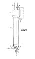
- the fluidized bed apparatus consists of a vertically standing cylindrical treatment vessel 1.
- This has a fluidization part at its lower end, which consists of a truncated cone-shaped jacket 2 that runs downwards from the cylinder cross section, a conical displacement body inserted into the truncated cone and tapering upwards 3 and at least one at the lowest point of the fluidization part essentially tangentially opening inlet pipe 4 for the treatment gas.
- a calming part 5 with an outlet pipe 6 for the exhaust gas is arranged above the treatment vessel 1.
- the calming part 5 advantageously has a somewhat larger cross section than the treatment vessel 1 in order to lower the flow rate of the carrier gas below the sinking rate of the fluidized soot particles.
- a soot discharge tube 8 connected axially to a lock 7 is inserted. It opens into the tapered end of the displacement body 3.
- a soot supply 10 connected to a metering lock 9 opens.
- the lock 9 is fed with soot from a bunker arranged above it. In the case of loading from a lower soot bunker, the soot is metered into a pneumatic conveying device by means of the lock 9 and in a separating device connected to the soot supply 10, e.g. B. a cyclone, separated from the flow and fed into the head part 5 of the apparatus.
- an optical-electrical sensor 11 is provided at the transition between treatment vessel 1 and sedative part 5 brings, which converts the optical density at the measuring point into electrical voltage.
- This sensor 11 which is switched as a limit value transmitter, controls the metering lock 9.
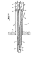
- a particularly advantageous and reliable embodiment of the limit indicator which is an independent object of the invention, consists of a hairpin-shaped light guide 12 which has an interruption 13 serving as a measuring section on one leg.
- the two legs of the interrupted light guide end in a measuring head 14 consisting of two light-tight chambers.
- One of the chambers contains a light source 15, from which one leg end of the light guide 12 is exposed to light.
- a light receiver 16 which is connected to the second leg end of the light guide.
- a measuring amplifier for amplifying the light-dependent electrical signal of the light receiver is also expediently accommodated in the measuring head.
- the two legs of the light guide 12 are located in guide tubes 17 and 18.
- the light guide legs are locked by seals 19 and the guide tubes are sealed gas-tight.
- the light guide 12 and the guide tubes 17 and 18 are surrounded by a common protective tube 20, which is provided with a flange 21 or a similar device, with the aid of which the measuring probe is attached to the container wall in a gas-tight manner, that the measuring section 13 comes to rest in the interior of the container, but the measuring head 14 is located outside the container.
- its surface is e.g. B. formed particularly smooth by polishing or smooth melting.
- the limit transmitter can contain a purge line 22, which at its end has at least one outlet opening 23 directed towards the measuring section 13, with the aid of which purging gas pulses can be periodically applied to the measuring section.
- the process for treating fluidized soot in countercurrent with gases can be carried out in such a way that the treated soot is discharged from the fluidized bed in a time-constant mass flow and the starting soot is fed in in such an amount that the level of the fluidized bed is kept constant.
- the soot can also be introduced into the fluidized bed via the lock 9 in a time-constant mass flow.
- the soot discharge by means of the lock 7 is controlled by the limit switch 11 in such a way that the lock 7 is started when the limit switch 11 is immersed in the fluidized bed and is stopped or slowed down when the level of the fluidized bed is below the height determined by the limit switch sinks.
Landscapes
- Chemical & Material Sciences (AREA)
- Organic Chemistry (AREA)
- Engineering & Computer Science (AREA)
- Combustion & Propulsion (AREA)
- Chemical Kinetics & Catalysis (AREA)
- Devices And Processes Conducted In The Presence Of Fluids And Solid Particles (AREA)
- Pigments, Carbon Blacks, Or Wood Stains (AREA)
Applications Claiming Priority (2)
| Application Number | Priority Date | Filing Date | Title |
|---|---|---|---|
| DE19843423580 DE3423580A1 (de) | 1984-06-27 | 1984-06-27 | Verfahren zur behandlung von fluidisiertem russ mit gasen, fliessbettapparatur zur durchfuehrung des verfahrens und in der apparatur verwendbarer grenzwertgeber |
| DE3423580 | 1984-06-27 |
Publications (3)
| Publication Number | Publication Date |
|---|---|
| EP0167014A2 true EP0167014A2 (fr) | 1986-01-08 |
| EP0167014A3 EP0167014A3 (en) | 1987-09-09 |
| EP0167014B1 EP0167014B1 (fr) | 1990-01-24 |
Family
ID=6239210
Family Applications (1)
| Application Number | Title | Priority Date | Filing Date |
|---|---|---|---|
| EP85107048A Expired - Lifetime EP0167014B1 (fr) | 1984-06-27 | 1985-06-07 | Procédé de traitement de noir de carbone fluidisé par des gaz et appareil de fluidisation pour son application |
Country Status (4)
| Country | Link |
|---|---|
| US (2) | US4647444A (fr) |
| EP (1) | EP0167014B1 (fr) |
| JP (1) | JPS6119667A (fr) |
| DE (1) | DE3423580A1 (fr) |
Families Citing this family (17)
| Publication number | Priority date | Publication date | Assignee | Title |
|---|---|---|---|---|
| DE3721476C1 (de) * | 1987-06-30 | 1988-12-22 | Asea Brown Boveri | Verfahren zum Regeln der Wirbelschichthoehe in einem Pyrolysereaktor sowie Anordnung zur Durchfuehrung des Verfahrens |
| DE3816045A1 (de) * | 1987-09-11 | 1989-05-24 | Flowtec Ag | Lichtleitereinrichtung, insbesondere fuer massendurchflussmesser |
| US4940007A (en) * | 1988-08-16 | 1990-07-10 | A. Ahlstrom Corporation | Fast fluidized bed reactor |
| FI91971C (fi) * | 1992-04-10 | 1994-09-12 | Borealis Holding As | Leijupetireaktori |
| JP2518994B2 (ja) * | 1992-04-22 | 1996-07-31 | 富士通株式会社 | 半導体装置 |
| US5435972A (en) * | 1992-10-22 | 1995-07-25 | The United States Of America As Represented By The United States Department Of Energy | Fluidization quality analyzer for fluidized beds |
| US6301546B1 (en) * | 1999-01-22 | 2001-10-09 | Exxon Research And Engineering Company | Process for detecting and monitoring changes in properties of fluidized bed solids by pressure difference fluctuation measurement |
| ES2220481T3 (es) * | 1999-06-16 | 2004-12-16 | Marine Biotech Incorporated | Reactor de lecho fluidizado y procedimiento para el tratamiento de fluidos. |
| DE10211098A1 (de) * | 2002-03-14 | 2003-10-02 | Degussa | Verfahren zur Herstellung von nachbehandeltem Ruß |
| US20040140812A1 (en) * | 2003-01-21 | 2004-07-22 | Ademir Scallante | Arrangements containing electrical assemblies and methods of cleaning such electrical assemblies |
| EP1616914A1 (fr) * | 2004-07-12 | 2006-01-18 | Matter Engineering AG | Appareil pour la production de noir de carbone |
| JP4274124B2 (ja) * | 2005-01-11 | 2009-06-03 | 株式会社Ihi | 循環流動層燃焼装置の流動媒体循環量計測方法及び装置 |
| DE102005037336A1 (de) * | 2005-08-04 | 2007-02-08 | Degussa Ag | Kohlenstoffmaterial |
| DE102007060307A1 (de) * | 2007-12-12 | 2009-06-18 | Evonik Degussa Gmbh | Verfahren zur Nachbehandlung von Ruß |
| DE102008044116A1 (de) * | 2008-11-27 | 2010-06-02 | Evonik Degussa Gmbh | Pigmentgranulat, Verfahren zu dessen Herstellung und Verwendung |
| DE102010002244A1 (de) | 2010-02-23 | 2011-08-25 | Evonik Carbon Black GmbH, 63457 | Ruß, Verfahren zu seiner Herstellung und seine Verwendung |
| GB201811076D0 (en) * | 2018-07-05 | 2018-08-22 | Sensient Colors Uk Ltd | Nanoparticle dispersions |
Family Cites Families (21)
| Publication number | Priority date | Publication date | Assignee | Title |
|---|---|---|---|---|
| US2445327A (en) * | 1944-08-02 | 1948-07-20 | Hydrocarbon Research Inc | Fluidizing process for gasifying carbonaceous solids |
| US2761769A (en) * | 1952-07-17 | 1956-09-04 | Gulf Research Development Co | Fluidized catalytic apparatus |
| US2864674A (en) * | 1954-07-12 | 1958-12-16 | Phillips Petroleum Co | Process and apparatus for recovery of powdered materials such as carbon black |
| US2953437A (en) * | 1956-12-21 | 1960-09-20 | Phillips Petroleum Co | Process for treating carbon black pellets |
| DE1196808B (de) * | 1957-05-08 | 1965-07-15 | Degussa | Verfahren zum oxydativen Nachbehandeln von trockenem Russ |
| US3251337A (en) * | 1963-07-16 | 1966-05-17 | Robert E Latta | Spiral fluidized bed device and method for coating particles |
| US3318720A (en) * | 1963-10-14 | 1967-05-09 | Phillips Petroleum Co | Oxidation of carbon black |
| AT263405B (de) * | 1965-04-29 | 1968-07-25 | Hectronic Ag | Lichtelektrischer Flüssigkeitsdetektor |
| GB1187567A (en) * | 1966-03-31 | 1970-04-08 | Gas Council | Apparatus for use in producing a Fluidised Bed |
| DE2139865B2 (de) * | 1971-08-09 | 1976-12-02 | Ulrich, Helmut, Dipl.-Chem., 8000 München | Fuellstandsanzeiger oder zustandsdetektor mit einem durch eine trennwand hindurchgefuehrten, im wesentlichen geraden lichtleiterstab |
| US4138471A (en) * | 1976-06-01 | 1979-02-06 | J. M. Huber Corporation | Process for reducing the polycyclic aromatic hydrocarbon content of carbon black |
| US4080927A (en) * | 1976-10-06 | 1978-03-28 | General Atomic Company | Fluidized bed-gas coater apparatus |
| JPS53114861U (fr) * | 1977-02-19 | 1978-09-12 | ||
| GB2036326B (en) * | 1978-10-20 | 1983-08-17 | Klinger Ag | Liquid level sensor |
| JPS5588452U (fr) * | 1978-12-15 | 1980-06-18 | ||
| DE3118907A1 (de) * | 1981-05-13 | 1982-12-02 | Degussa Ag, 6000 Frankfurt | Verfahren zur entfernung von extrahierbaren bestandteilen aus russen |
| US4423006A (en) * | 1981-05-20 | 1983-12-27 | Uop Inc. | Fluid catalyst regeneration apparatus |
| US4468567A (en) * | 1981-05-21 | 1984-08-28 | Showa Electric Wire & Cable Co., Ltd. | Liquid level detecting device and method for producing the same |
| IT1150650B (it) * | 1982-03-10 | 1986-12-17 | Montedison Spa | Reattore a letto fluido |
| US4421523A (en) * | 1982-05-11 | 1983-12-20 | The United States Of America As Represented By The Department Of Energy | Control of bed height in a fluidized bed gasification system |
| US4453950A (en) * | 1982-09-20 | 1984-06-12 | The United States Of America As Represented By The United States Department Of Energy | Coal gasification system with a modulated on/off control system |
-
1984
- 1984-06-27 DE DE19843423580 patent/DE3423580A1/de active Granted
-
1985
- 1985-06-07 EP EP85107048A patent/EP0167014B1/fr not_active Expired - Lifetime
- 1985-06-21 US US06/747,609 patent/US4647444A/en not_active Expired - Fee Related
- 1985-06-26 JP JP60138087A patent/JPS6119667A/ja active Granted
-
1986
- 1986-01-14 US US06/818,590 patent/US4755358A/en not_active Expired - Fee Related
Also Published As
| Publication number | Publication date |
|---|---|
| JPH0125514B2 (fr) | 1989-05-18 |
| EP0167014A3 (en) | 1987-09-09 |
| EP0167014B1 (fr) | 1990-01-24 |
| US4647444A (en) | 1987-03-03 |
| DE3423580C2 (fr) | 1988-09-29 |
| US4755358A (en) | 1988-07-05 |
| DE3423580A1 (de) | 1986-01-02 |
| JPS6119667A (ja) | 1986-01-28 |
Similar Documents
| Publication | Publication Date | Title |
|---|---|---|
| EP0167014B1 (fr) | Procédé de traitement de noir de carbone fluidisé par des gaz et appareil de fluidisation pour son application | |
| DE2057528C3 (de) | Vorrichtung zur Durchführung von Reaktionen in Flüssigkeiten in Gegenwart von suspendierten Feststoffteilchen sowie Verwendung dieser Vorrichtung | |
| DE2227176A1 (de) | Verfahren zum Reinigen von quecksilberhaltigen Gasen | |
| DE2116481A1 (de) | Verfahren und Vorrichtung zum Bestrahlen von Flüssigkeiten | |
| EP0035973B1 (fr) | Dispositif pour le nettoyage en discontinu de gaz brut chargé de poussière | |
| DE3139078C2 (fr) | ||
| DE2506394A1 (de) | Wirbelschichtreaktor zur thermischen regenerierung von beladenen aktivkohlen | |
| DE2405669A1 (de) | Vorrichtung zum reinigen von abgas oder abluft | |
| DE7817177U1 (de) | Vorrichtung zur regenerierung von aktivkohle | |
| DE3909288C2 (de) | Verfahren zum Glaseinschmelzen von flüssigem radioaktivem Abfall | |
| EP0740110B1 (fr) | Procédé et appareil pour le traitement de résidus solides de combustion d'un incinérateur | |
| DE2436792A1 (de) | Verfahren zur reinigung von abwaessern mittels aktivkohle | |
| DE3815082C2 (fr) | ||
| DE2749399C2 (de) | Vorrichtung zum thermischen Regenerieren von beladenen Adsorbentien | |
| DE2901529C2 (de) | Verfahren und Vorrichtung zur kontinuierlichen Entfernung von unerwünschten Bestandteilen aus Feststoffpartikeln mit einem Lösungsmittel im Gegenstrom | |
| DE972373C (de) | Abscheidevorrichtung zur Rueckgewinnung fester Schwebteilchen aus Gas oder Dampf mit einer Staubkammer und einem nachgeschalteten Zyklon mit Spuelaustrag | |
| DE3021037C2 (de) | Vorrichtung und Verfahren zum Entladen eines Wirbelschichtofens für die Beschichtung von Hochtemperaturreaktor (HTR)-Brennstoffen | |
| EP0620037A2 (fr) | Procédé et dispositif pour la purification de l'air | |
| EP0180074A1 (fr) | Incinérateur | |
| DE2411006C2 (de) | Vorrichtung zur Gasphasenumsetzung von Wasserstoff und Sauerstoff | |
| EP0623378A1 (fr) | Procédé d'épuration de gaz d'échappement et dispositif mettant en oeuvre ce procédé | |
| EP0147617B1 (fr) | Appareil et procédé pour la régénération d'adsorbants carbonacés chargés, secs et sous forme pulvérulente | |
| DE2246806C2 (de) | Verfahren zur Reinigung von Abgasen | |
| DE4234111C2 (de) | Verfahren und Vorrichtung zur Reinigung kontaminierter Böden | |
| DE4126058A1 (de) | Verfahren zur dekontaminierung von mit fluechtigen organischen verbindungen belastetem material |
Legal Events
| Date | Code | Title | Description |
|---|---|---|---|
| PUAI | Public reference made under article 153(3) epc to a published international application that has entered the european phase |
Free format text: ORIGINAL CODE: 0009012 |
|
| 17P | Request for examination filed |
Effective date: 19850607 |
|
| AK | Designated contracting states |
Designated state(s): FR GB IT NL |
|
| EL | Fr: translation of claims filed | ||
| TCNL | Nl: translation of patent claims filed | ||
| ITCL | It: translation for ep claims filed |
Representative=s name: BARZANO' E ZANARDO ROMA S.P.A. |
|
| PUAL | Search report despatched |
Free format text: ORIGINAL CODE: 0009013 |
|
| AK | Designated contracting states |
Kind code of ref document: A3 Designated state(s): FR GB IT NL |
|
| 17Q | First examination report despatched |
Effective date: 19881025 |
|
| GRAA | (expected) grant |
Free format text: ORIGINAL CODE: 0009210 |
|
| AK | Designated contracting states |
Kind code of ref document: B1 Designated state(s): FR GB IT NL |
|
| ET | Fr: translation filed | ||
| ITF | It: translation for a ep patent filed | ||
| GBT | Gb: translation of ep patent filed (gb section 77(6)(a)/1977) | ||
| PLBE | No opposition filed within time limit |
Free format text: ORIGINAL CODE: 0009261 |
|
| STAA | Information on the status of an ep patent application or granted ep patent |
Free format text: STATUS: NO OPPOSITION FILED WITHIN TIME LIMIT |
|
| 26N | No opposition filed | ||
| PGFP | Annual fee paid to national office [announced via postgrant information from national office to epo] |
Ref country code: GB Payment date: 19910528 Year of fee payment: 7 |
|
| PGFP | Annual fee paid to national office [announced via postgrant information from national office to epo] |
Ref country code: FR Payment date: 19910627 Year of fee payment: 7 |
|
| ITTA | It: last paid annual fee | ||
| PGFP | Annual fee paid to national office [announced via postgrant information from national office to epo] |
Ref country code: NL Payment date: 19910630 Year of fee payment: 7 |
|
| PG25 | Lapsed in a contracting state [announced via postgrant information from national office to epo] |
Ref country code: GB Effective date: 19920607 |
|
| PG25 | Lapsed in a contracting state [announced via postgrant information from national office to epo] |
Ref country code: NL Effective date: 19930101 |
|
| GBPC | Gb: european patent ceased through non-payment of renewal fee |
Effective date: 19920607 |
|
| NLV4 | Nl: lapsed or anulled due to non-payment of the annual fee | ||
| PG25 | Lapsed in a contracting state [announced via postgrant information from national office to epo] |
Ref country code: FR Effective date: 19930226 |
|
| REG | Reference to a national code |
Ref country code: FR Ref legal event code: ST |