EP0167086A2 - Echangeur de chaleur Joule-Thomson et cryostat - Google Patents
Echangeur de chaleur Joule-Thomson et cryostat Download PDFInfo
- Publication number
- EP0167086A2 EP0167086A2 EP85107821A EP85107821A EP0167086A2 EP 0167086 A2 EP0167086 A2 EP 0167086A2 EP 85107821 A EP85107821 A EP 85107821A EP 85107821 A EP85107821 A EP 85107821A EP 0167086 A2 EP0167086 A2 EP 0167086A2
- Authority
- EP
- European Patent Office
- Prior art keywords
- tube
- orifice
- fibrous material
- joule
- heat exchanger
- Prior art date
- Legal status (The legal status is an assumption and is not a legal conclusion. Google has not performed a legal analysis and makes no representation as to the accuracy of the status listed.)
- Ceased
Links
Images
Classifications
-
- F—MECHANICAL ENGINEERING; LIGHTING; HEATING; WEAPONS; BLASTING
- F25—REFRIGERATION OR COOLING; COMBINED HEATING AND REFRIGERATION SYSTEMS; HEAT PUMP SYSTEMS; MANUFACTURE OR STORAGE OF ICE; LIQUEFACTION SOLIDIFICATION OF GASES
- F25B—REFRIGERATION MACHINES, PLANTS OR SYSTEMS; COMBINED HEATING AND REFRIGERATION SYSTEMS; HEAT PUMP SYSTEMS
- F25B9/00—Compression machines, plants or systems, in which the refrigerant is air or other gas of low boiling point
- F25B9/02—Compression machines, plants or systems, in which the refrigerant is air or other gas of low boiling point using Joule-Thompson effect; using vortex effect
-
- F—MECHANICAL ENGINEERING; LIGHTING; HEATING; WEAPONS; BLASTING
- F25—REFRIGERATION OR COOLING; COMBINED HEATING AND REFRIGERATION SYSTEMS; HEAT PUMP SYSTEMS; MANUFACTURE OR STORAGE OF ICE; LIQUEFACTION SOLIDIFICATION OF GASES
- F25B—REFRIGERATION MACHINES, PLANTS OR SYSTEMS; COMBINED HEATING AND REFRIGERATION SYSTEMS; HEAT PUMP SYSTEMS
- F25B2309/00—Gas cycle refrigeration machines
- F25B2309/02—Gas cycle refrigeration machines using the Joule-Thompson effect
- F25B2309/022—Gas cycle refrigeration machines using the Joule-Thompson effect characterised by the expansion element
-
- F—MECHANICAL ENGINEERING; LIGHTING; HEATING; WEAPONS; BLASTING
- F25—REFRIGERATION OR COOLING; COMBINED HEATING AND REFRIGERATION SYSTEMS; HEAT PUMP SYSTEMS; MANUFACTURE OR STORAGE OF ICE; LIQUEFACTION SOLIDIFICATION OF GASES
- F25B—REFRIGERATION MACHINES, PLANTS OR SYSTEMS; COMBINED HEATING AND REFRIGERATION SYSTEMS; HEAT PUMP SYSTEMS
- F25B2500/00—Problems to be solved
- F25B2500/01—Geometry problems, e.g. for reducing size
Definitions
- This invention pertains to cryogenic refrigeration systems, most commonly referred to as cryostats, used in cryo-electronic systems such as cooling infra-red detectors and the like. These systems are useful in both fixed ground operations and in airborne detection systems. Such systems produce refrigeration by expansion of gas through an orifice which is the well-known Joule-Thomson effect or cooling cycle.
- An effective flow restrictor can be achieved in a Joule-Thomson (JT) heat exchanger by inserting a fine fibrous material (composed of individual fibers) into the high pressure tube at what would normally be the outlet and crushing or deforming the tube over the fiber to create the flow restrictor. Fibers or a fibrous or non-fibrous hydrophilic material can also be inserted in other portions of the high pressure tube to absorb water and minimize the migration of ice crystals to the flow restrictor and prevent ice blockage within the restrictor. Furthermore.
- JT Joule-Thomson
- Joule-Thomson coolers In order to develop small Joule-Thomson coolers to deliver refrigeration for cooling an object such as an infra-red detector, one of the most difficult problems to overcome was development of a low flow Joule-Thomson (JT) flow restrictor which is not prone to blockage of its necessarily tiny passages. Blockage comes about by virtue of water vapor in the refrigeration gas (e.g. argon), which as the temperature of the gas decreases on its way toward the JT orifice, the water freezes with the resulting ice crystals tending to block the necessarily small JT orifice.
- the refrigeration gas e.g. argon
- cryostats with a fixed orifice are limited to a 0.004 inch (0.1 mm) minimum inside diameter JT flow restrictor tube. Tubes smaller than this are easily blocked by minute, unavoidable impurities in the gas stream.
- a 0.004 inch (0.1 mm) tube used as a flow restriction in the JT system requires a comparatively large gas flow in order to maintain the pressure drop required for JT operation.
- the large gas flow dictates a large heat exchanger, the smallest current JT refrigerators being 1.1 inch long.
- a lower flow rate refrigerator could be achieved if a sub-miniature demand flow JT valve mechanism were available or if a high flow impedance could be developed which is not prone to flow blockage by impurities.
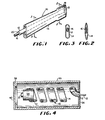
- the heat exchanger 10 includes an inner or high pressure tube 12 disposed within an outer or low pressure tube 14. End 13 of low pressure tube 19 is sealed as by soldering. Disposed within high pressure tube 12 is an elongated fibrous material 16. As shown in Figure 2, the end 18 of tube 12 which will be designated the orifice end is crushed over the thread to provide the flow restrictor. As shown in Figure 3, the low pressure tube 14 is deformed along at least a portion of its length and preferably all of its length to provide intimate contact between the low pressure tube 14 and the high pressure tube 12 to enhance heat transfer between the two.
- the heat exchanger of Figure 1 is preferably constructed from stainless steel tubing and the preferred fiber is a mercerized cotton or other hydrophilic material (fibers, zeolite resins and the like). although fine fibers of silk. glass, metal or plastic would work. If cotton fiber or other hydrophilic material is disposed through the length of the high pressure tube, it can act to absorb moisture in that region where the gas has not been cooled enough to cause ice to form. Furthermore, cotton or any other fiber can serve to prevent migration of ice crystals to the orifice after they are formed upstream of the orifice. Lastly. all fibers can be used in conjunction with deformation of the end of the high pressure tube to form an orifice with an effective flow restrictor.
- the end 20 of the high pressure tube 12 is connected to a source of high pressure gas such as argon. As the gas moves from end 20 toward end 18 of the high pressure tube, it is cooled. Condensable impurities in the gas (e.g. water) condense to form a mist of ice crystals in the gas and/or form a deposit on the tube walls.
- the fibers in the heat exchange section prevent the migration of the ice crystals to the flow restrictor.
- the function of the fiber in the flow restrictor (crushed section of the tube as shown in Figure 2) is to:
- a device is constructed wherein the high pressure tube 12 is 0.022 inches (0.56 mm) OD by 0.0115 inches (0.24 mm) ID, which is filled with parallel lengths of fine cotton thread (size 50).
- the gas after passing through the crushed section at end 18 ( Figure 2) is at a low pressure and moves from the right to the left through the low pressure tube 14 0.04 inches (1.0 mm) OD by 0.03 inches (0.75 mm) ID.
- the low pressure tube has been deformed or crushed in order to be put in good thermal contact with the inner high pressure tube in order to effect pre-cooling of the high pressure fluid as it travel to the orifice end 18 of tube 12.
- FIG 4 shows a Joule-Thomson heat exchanger 10 according to the present invention disposed inside of a vacuum housing 30 to be used as a cryostat to cool an infra-red detector 32.
- a portion of helically wound heat exchanger 10 is disposed around and in intimate contact with an infra-red detector heat station 34.
- Heat station 34 can be fixed to the inner wall of housing 30 by supports (not shown) which have low heat conductivity properties.
- Heat exchanger 10 is supported by being soldered to cover 36 of housing 30.
- Housing 30 has disposed on its forward end 38 an infra-red window.
- Heat exchanger 10 includes a high pressure tube 12 which on one end extends beyond low pressure tube 14 outwardly of housing 30 to facilitate connecting tube 12 to a source of high pressure fluid, e.g., argon.
- Tube 12 on the other end, terminates in a Joule-Thomson orifice 17 adjacent heat station 34.
- the heat exchanger 10 terminates at heat station 34 so that the heat station 34 can be effectively cooled and transmit refrigeration to I-R detector 32.
- a refrigerator of this type was found to cool the heat station 34 to less than 100°K for one hour when supplied by gas at 1600 psi (10.9 H P a) or greater. Gas flows of 4 standard cubic centimeters per second or greater of argon were required.
Landscapes
- Engineering & Computer Science (AREA)
- Physics & Mathematics (AREA)
- Mechanical Engineering (AREA)
- Thermal Sciences (AREA)
- General Engineering & Computer Science (AREA)
- Devices That Are Associated With Refrigeration Equipment (AREA)
- Containers, Films, And Cooling For Superconductive Devices (AREA)
Applications Claiming Priority (2)
| Application Number | Priority Date | Filing Date | Title |
|---|---|---|---|
| US06/625,925 US4653284A (en) | 1984-06-29 | 1984-06-29 | Joule-Thomson heat exchanger and cryostat |
| US625925 | 2000-07-26 |
Publications (2)
| Publication Number | Publication Date |
|---|---|
| EP0167086A2 true EP0167086A2 (fr) | 1986-01-08 |
| EP0167086A3 EP0167086A3 (fr) | 1986-11-12 |
Family
ID=24508202
Family Applications (1)
| Application Number | Title | Priority Date | Filing Date |
|---|---|---|---|
| EP85107821A Ceased EP0167086A3 (fr) | 1984-06-29 | 1985-06-24 | Echangeur de chaleur Joule-Thomson et cryostat |
Country Status (4)
| Country | Link |
|---|---|
| US (1) | US4653284A (fr) |
| EP (1) | EP0167086A3 (fr) |
| JP (1) | JPS6129658A (fr) |
| CA (1) | CA1259499A (fr) |
Cited By (3)
| Publication number | Priority date | Publication date | Assignee | Title |
|---|---|---|---|---|
| EP0229666A1 (fr) * | 1986-01-14 | 1987-07-22 | Apd Cryogenics Inc. | Echangeur de chaleur à tubes enroulés parallèlement |
| EP0239375A3 (fr) * | 1986-03-24 | 1988-11-17 | British Aerospace Public Limited Company | Dispositif d'alimentation en fluide décontaminé et systèmes cryogéniques utilisant un tel dispositif |
| EP0167161B1 (fr) * | 1984-07-05 | 1989-11-08 | Apd Cryogenics Inc. | Echangeur de chaleur à tubes enroulés parallèlement |
Families Citing this family (4)
| Publication number | Priority date | Publication date | Assignee | Title |
|---|---|---|---|---|
| US5060481A (en) * | 1989-07-20 | 1991-10-29 | Helix Technology Corporation | Method and apparatus for controlling a cryogenic refrigeration system |
| US5687574A (en) * | 1996-03-14 | 1997-11-18 | Apd Cryogenics, Inc. | Throttle cycle cryopumping system for Group I gases |
| US5787713A (en) * | 1996-06-28 | 1998-08-04 | American Superconductor Corporation | Methods and apparatus for liquid cryogen gasification utilizing cryoelectronics |
| US6173577B1 (en) | 1996-08-16 | 2001-01-16 | American Superconductor Corporation | Methods and apparatus for cooling systems for cryogenic power conversion electronics |
Family Cites Families (18)
| Publication number | Priority date | Publication date | Assignee | Title |
|---|---|---|---|---|
| DE308199C (fr) * | ||||
| US1711270A (en) * | 1926-09-28 | 1929-04-30 | Copeland Products Inc | Refrigerating system |
| US2073863A (en) * | 1936-02-01 | 1937-03-16 | Crosley Radio Corp | Capillary tube device |
| FR973633A (fr) * | 1941-10-21 | 1951-02-13 | Barberis & Neveux Ets | Détendeur, notamment pour installations frigorigènes |
| US2448315A (en) * | 1945-02-14 | 1948-08-31 | Gen Motors Corp | Combination restrictor and heat exchanger |
| US2548643A (en) * | 1946-11-09 | 1951-04-10 | Gen Electric | Refrigerant flow controlling device |
| US2909908A (en) * | 1956-11-06 | 1959-10-27 | Little Inc A | Miniature refrigeration device |
| GB863961A (en) * | 1959-01-23 | 1961-03-29 | Hymatic Eng Co Ltd | Improvements relating to gas liquefiers |
| US3048021A (en) * | 1959-02-17 | 1962-08-07 | Itt | Joule-thomson effect gas liquefier |
| US3006157A (en) * | 1960-05-04 | 1961-10-31 | Union Carbide Corp | Cryogenic apparatus |
| US3063260A (en) * | 1960-12-01 | 1962-11-13 | Specialties Dev Corp | Cooling device employing the joule-thomson effect |
| US3205679A (en) * | 1961-06-27 | 1965-09-14 | Air Prod & Chem | Low temperature refrigeration system having filter and absorber means |
| FR1412604A (fr) * | 1963-09-06 | 1965-10-01 | Little Inc A | Tube de transport de fluides cryogènes comportant un appareil de liquéfaction |
| US3320755A (en) * | 1965-11-08 | 1967-05-23 | Air Prod & Chem | Cryogenic refrigeration system |
| US3714796A (en) * | 1970-07-30 | 1973-02-06 | Air Prod & Chem | Cryogenic refrigeration system with dual circuit heat exchanger |
| US3728868A (en) * | 1971-12-06 | 1973-04-24 | Air Prod & Chem | Cryogenic refrigeration system |
| US4237699A (en) * | 1979-05-23 | 1980-12-09 | Air Products And Chemicals, Inc. | Variable flow cryostat with dual orifice |
| IT1122400B (it) * | 1979-08-02 | 1986-04-23 | Medical Const Service Mcs | Dispositivo perfezionato per trattamenti di criochirurgia e relativo complesso scambiatore ad alto rendimento |
-
1984
- 1984-06-29 US US06/625,925 patent/US4653284A/en not_active Expired - Fee Related
-
1985
- 1985-06-24 CA CA000484999A patent/CA1259499A/fr not_active Expired
- 1985-06-24 EP EP85107821A patent/EP0167086A3/fr not_active Ceased
- 1985-06-27 JP JP14147185A patent/JPS6129658A/ja active Pending
Cited By (3)
| Publication number | Priority date | Publication date | Assignee | Title |
|---|---|---|---|---|
| EP0167161B1 (fr) * | 1984-07-05 | 1989-11-08 | Apd Cryogenics Inc. | Echangeur de chaleur à tubes enroulés parallèlement |
| EP0229666A1 (fr) * | 1986-01-14 | 1987-07-22 | Apd Cryogenics Inc. | Echangeur de chaleur à tubes enroulés parallèlement |
| EP0239375A3 (fr) * | 1986-03-24 | 1988-11-17 | British Aerospace Public Limited Company | Dispositif d'alimentation en fluide décontaminé et systèmes cryogéniques utilisant un tel dispositif |
Also Published As
| Publication number | Publication date |
|---|---|
| US4653284A (en) | 1987-03-31 |
| CA1259499A (fr) | 1989-09-19 |
| JPS6129658A (ja) | 1986-02-10 |
| EP0167086A3 (fr) | 1986-11-12 |
Similar Documents
| Publication | Publication Date | Title |
|---|---|---|
| US2909908A (en) | Miniature refrigeration device | |
| US3018643A (en) | Cryogenic refrigerating means | |
| US4726194A (en) | Transfer system | |
| US3320755A (en) | Cryogenic refrigeration system | |
| US2991633A (en) | Joule-thomson effect cooling system | |
| US4653284A (en) | Joule-Thomson heat exchanger and cryostat | |
| US4484458A (en) | Apparatus for condensing liquid cryogen boil-off | |
| US4694662A (en) | Condensing sub-cooler for refrigeration systems | |
| US2955439A (en) | Heat pump including drain pan heating means | |
| US3055191A (en) | Cooling device | |
| US3898856A (en) | Water chilling method and apparatus | |
| US3064451A (en) | Cooling head for small chambers | |
| US3350895A (en) | Defrost means for non-reversible refrigeration systems | |
| US2481968A (en) | Refrigerant flow controlling device | |
| US2430938A (en) | Means for and method of defrosting refrigerating apparatus | |
| US4887433A (en) | Liquefied gas transfer line having at least one bypass for the vapors of said gas | |
| US3635039A (en) | Vapor traps | |
| CA2256768C (fr) | Systeme de refrigeration avec echangeur de chaleur a rendement ameliore | |
| JPS5986276A (ja) | クライオスタツト | |
| US4030900A (en) | Cooling device | |
| US2492054A (en) | Refrigeration thermostatic control | |
| US3037360A (en) | Production of cold refrigerant gas | |
| KR20000010862U (ko) | 냉동 공조기용 관체노즐 | |
| US2056016A (en) | Flow controlling device for refrigerating systems | |
| FR2320510A1 (fr) | Installation de refrigeration |
Legal Events
| Date | Code | Title | Description |
|---|---|---|---|
| PUAI | Public reference made under article 153(3) epc to a published international application that has entered the european phase |
Free format text: ORIGINAL CODE: 0009012 |
|
| AK | Designated contracting states |
Designated state(s): DE FR GB IT |
|
| PUAL | Search report despatched |
Free format text: ORIGINAL CODE: 0009013 |
|
| AK | Designated contracting states |
Kind code of ref document: A3 Designated state(s): DE FR GB IT |
|
| 17P | Request for examination filed |
Effective date: 19870206 |
|
| 17Q | First examination report despatched |
Effective date: 19871012 |
|
| STAA | Information on the status of an ep patent application or granted ep patent |
Free format text: STATUS: THE APPLICATION HAS BEEN REFUSED |
|
| 18R | Application refused |
Effective date: 19890325 |
|
| RIN1 | Information on inventor provided before grant (corrected) |
Inventor name: STEYERT, WILLIAM ALBERT |