EP0167116A2 - Schlauchschelle mit Spannschloss - Google Patents
Schlauchschelle mit Spannschloss Download PDFInfo
- Publication number
- EP0167116A2 EP0167116A2 EP85107981A EP85107981A EP0167116A2 EP 0167116 A2 EP0167116 A2 EP 0167116A2 EP 85107981 A EP85107981 A EP 85107981A EP 85107981 A EP85107981 A EP 85107981A EP 0167116 A2 EP0167116 A2 EP 0167116A2
- Authority
- EP
- European Patent Office
- Prior art keywords
- tensioning
- housing base
- band
- strap
- hose clamp
- Prior art date
- Legal status (The legal status is an assumption and is not a legal conclusion. Google has not performed a legal analysis and makes no representation as to the accuracy of the status listed.)
- Granted
Links
Images

Classifications
-
- F—MECHANICAL ENGINEERING; LIGHTING; HEATING; WEAPONS; BLASTING
- F16—ENGINEERING ELEMENTS AND UNITS; GENERAL MEASURES FOR PRODUCING AND MAINTAINING EFFECTIVE FUNCTIONING OF MACHINES OR INSTALLATIONS; THERMAL INSULATION IN GENERAL
- F16L—PIPES; JOINTS OR FITTINGS FOR PIPES; SUPPORTS FOR PIPES, CABLES OR PROTECTIVE TUBING; MEANS FOR THERMAL INSULATION IN GENERAL
- F16L33/00—Arrangements for connecting hoses to rigid members; Rigid hose-connectors, i.e. single members engaging both hoses
- F16L33/02—Hose-clips
- F16L33/08—Hose-clips in which a worm coacts with a part of the hose-encircling member that is toothed like a worm-wheel
-
- Y—GENERAL TAGGING OF NEW TECHNOLOGICAL DEVELOPMENTS; GENERAL TAGGING OF CROSS-SECTIONAL TECHNOLOGIES SPANNING OVER SEVERAL SECTIONS OF THE IPC; TECHNICAL SUBJECTS COVERED BY FORMER USPC CROSS-REFERENCE ART COLLECTIONS [XRACs] AND DIGESTS
- Y10—TECHNICAL SUBJECTS COVERED BY FORMER USPC
- Y10T—TECHNICAL SUBJECTS COVERED BY FORMER US CLASSIFICATION
- Y10T24/00—Buckles, buttons, clasps, etc.
- Y10T24/14—Bale and package ties, hose clamps
- Y10T24/1412—Bale and package ties, hose clamps with tighteners
- Y10T24/1427—Worm and tooth
-
- Y—GENERAL TAGGING OF NEW TECHNOLOGICAL DEVELOPMENTS; GENERAL TAGGING OF CROSS-SECTIONAL TECHNOLOGIES SPANNING OVER SEVERAL SECTIONS OF THE IPC; TECHNICAL SUBJECTS COVERED BY FORMER USPC CROSS-REFERENCE ART COLLECTIONS [XRACs] AND DIGESTS
- Y10—TECHNICAL SUBJECTS COVERED BY FORMER USPC
- Y10T—TECHNICAL SUBJECTS COVERED BY FORMER US CLASSIFICATION
- Y10T24/00—Buckles, buttons, clasps, etc.
- Y10T24/14—Bale and package ties, hose clamps
- Y10T24/1412—Bale and package ties, hose clamps with tighteners
- Y10T24/1427—Worm and tooth
- Y10T24/1429—Pivotal worm band clamp
-
- Y—GENERAL TAGGING OF NEW TECHNOLOGICAL DEVELOPMENTS; GENERAL TAGGING OF CROSS-SECTIONAL TECHNOLOGIES SPANNING OVER SEVERAL SECTIONS OF THE IPC; TECHNICAL SUBJECTS COVERED BY FORMER USPC CROSS-REFERENCE ART COLLECTIONS [XRACs] AND DIGESTS
- Y10—TECHNICAL SUBJECTS COVERED BY FORMER USPC
- Y10T—TECHNICAL SUBJECTS COVERED BY FORMER US CLASSIFICATION
- Y10T24/00—Buckles, buttons, clasps, etc.
- Y10T24/14—Bale and package ties, hose clamps
- Y10T24/1412—Bale and package ties, hose clamps with tighteners
- Y10T24/1441—Tangential screw
Definitions
- the invention relates to a hose clamp according to the preamble of claim 1.
- the one end region of the tensioning strap is fastened to the bottom of the U-shaped housing of the turnbuckle by projecting tabs arranged on the front and back of the housing bottom through punched-outs in the tensioning strap and onto the tensioning strap are bent.
- This mounting of the tensioning strap is often unsatisfactory in cases of high tensioning forces of the tensioning strap, since this can result in the tensioning strap being torn out of its fastenings on the housing base and the hose clamp thereby becoming unusable.
- This form-fitting anchoring of the tension band in the housing base allows particularly high tension forces to be transmitted to the housing base and there is no longer the risk of the anchorage of the tensioning strap being torn out on the housing base.
- the anchoring according to the invention withstands considerably higher clamping forces than the previously known anchoring according to DE-OS 31 30 112.
- the measure according to the invention thus enables the use of considerably increased tensioning forces of the tensioning strap without the risk of the anchorage of the tensioning strap being torn out on the housing base.
- the measure according to the invention is structurally simple and inexpensive and extremely reliable. Also the assembly of the strap on
- Housing bottom can be carried out extremely simply and inexpensively, since the connection of the tensioning strap to the housing bottom at its offset in the transverse slot of the housing bottom is form-fitting and therefore only inserting the tensioning strap into the transverse slot of the housing bottom is necessary here.
- the metallic strap can preferably be made of steel, but in some cases other metals, such as brass or the like, are also suitable.
- the strap can also expediently be elastically flexible. However, it is also possible and in many cases expedient if the tensioning strap is essentially inelastic and flexible.
- the thickness of the tensioning band can, for example, expediently be 0.4 to 1.5 mm and its width expediently 5 to 20 mm. However, it can also have greater or lesser thicknesses and widths.
- the tensioning strap To mount the tensioning strap on the housing base, it can be expediently inserted through the transverse slot until the crossbar of its angled portion comes to rest in the transverse slot. You can then secure the strap against pulling out of the cross slot.
- This securing can expediently take place in that a narrow tab with the housing base is arranged in one piece on the housing base, which extends through a hole-shaped punching out of the tensioning band and onto the Top of the strap is bent.
- this flap does not need to participate in the transfer of the tensioning force of the tensioning strap to the housing base, so that it can easily penetrate the hole of the tensioning strap assigned to it with all-round play in it, which is even particularly expedient.
- This tension band then does not need to have any perforations for this protection against swiveling up, likewise not if one provides for the end region of the tension band held on the housing base to be bent in a hook shape around the rear end of the housing base by approximately 180 °, which gives the tension band particularly good hold on the housing base in Connection with the bend of the strap results.
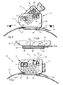
- the hose clamp 10 shown in the drawing has a quick-release fastener in the form of a quick-action lock 11, which consists of a housing 12 and a hinged cover 13 with a tensioning screw 14 rotatably mounted in the hinged cover 13.
- the tension band 17, which has a conventional helical toothing, is anchored with its one end region 19 to the housing base 18 of the housing 12 which is U-shaped in front view.
- This anchorage has a transverse slot 26 in the housing base 18, the length of which is somewhat greater than the constant width of this tensioning strap 17 over the entire length of the tensioning strap 17.
- the width of this transverse slot 26 is slightly larger than the constant thickness of the tension band.
- This transverse slot 26 extends perpendicular to the longitudinal direction of the tension band 17 and serves for the positive anchoring of this tension band end region 19 in such a way that this tension band end region has an offset (cranking) 23 on this transverse slot 26, which is formed by two opposing, right-angled bends of the tension band extending over the full width of the unperforated tension band, the spacing of which from one another is approximately the thickness of the housing base 18 and thus approximately corresponds to the height of the transverse slot 26.
- the transverse web 24 of the tensioning band formed by the offset 23 comes to lie in this transverse slot 26 and is directed approximately perpendicular to the longitudinal direction of the housing base 18.
- This crosspiece 24 thus has the same width and thickness as the adjoining longitudinal regions 21 and 22 of the tensioning band, of which the longitudinal region 22 on the underside 45 of the housing base 18 facing away from the free end 99 'of this tensioning band end region 19, relative to the crosspiece 24 and the longitudinal region 21 leading from the crosspiece 24 to this free end 19 'rests on the upper side 46 of the housing base located inside the housing.
- the U-shaped housing 12 of the turnbuckle has two longitudinal side walls 38, 39 which run parallel to one another and are angled at right angles to the housing base 18.
- the clear interior between them has a width that is slightly larger than the width of the tension band 17.
- the transverse slot 26 in the housing base extends from one longitudinal side wall 38 to the other longitudinal side wall 39, so that the tension band 17 can penetrate it over its full width. As long as the tensioning strap 17 is not tensioned, the cross piece 24 lies loosely in the transverse slot 26 of the housing base 18.
- the tensioning band is tensioned, then the tensioning region 19 is pulled in the direction of the arrow A and as a result the transverse web 24, thereby holding this tensioning band on the housing base 18, against the longitudinal side wall on the right in relation to FIG. 4 28 of the transverse slot 26 pressed and thereby transmits the entire clamping force exerted on this end region 19 in the direction of arrow A onto the housing base 18, so that the tensile connection required for holding the tensioning band 17 during its tensioning between the tensioning band end region 19 and the housing base 18 through this the cranked region 23 of the tension band end region 19 penetrating the transverse slot 26 is effected.
- This fuse is, in this embodiment of a flap 16 which is integrally formed on the housing bottom 18, namely at its the end 19 'of the S pannbandendbe- rich 19 adjacent end, and the tab 16 penetrating a hole-shaped punched-out 15 of the tension band and is bent onto the upper side of the tension band end region 19 resting on the housing base 18, as shown in FIGS. 3 and 4.
- This backup does not have the task of transmitting clamping forces of the clamping band 17 to the housing base 18, and therefore the tab 16 can easily penetrate the punching 15 of the clamping band 17 with circumferential play on all sides.
- the tensioning strap 17 leads from its end area 19 back to the housing 12 in a circle and the other free end 20 of this tensioning strap 17 is passed through the housing 12 above the anchored tensioning strap end area 19 and the tensioning strap can thus be opened with the hinged lid 13 (FIG. 2 ) pull through the housing 12 by hand.
- this tightening strap 17 comprises a hose or the like to be fastened on a connecting piece or the like, one can already tighten the tightening strap 17 by hand as far as possible when the hinged lid 13 is folded up, and then one folds the hinged lid 13 out of the position shown in FIG Open position shown in the closed position shown in Fig. 1 down, whereby the thread of the worm 14 comes into engagement with the teeth of the strap 17 and now the strap 17 can no longer be moved by hand, but only by turning the worm 14.
- the tensioning screw 14 is rotatably supported in the hinged cover 13 by the hinged cover 13 being U-shaped in side view and the screws sharp penetrates a bearing bore of the rear leg 32 of this hinged cover 13 and furthermore the neck of the worm 14, which is reduced in diameter compared to the thread of the tensioning worm 14 and its head, is inserted into a bearing slot of the front leg 25 of the hinged cover 13 which is open on the underside and the two forming this bearing slot Webs are bent towards each other below the neck, so that the neck is rotatably mounted in this longitudinal slot of the front leg 25 and can no longer get out of it.
- the head of the screw 14 has a slot for a screwdriver. Other head designs are also possible, preferably with a hexagon socket.
- the two longitudinal side walls 38, 39 of the housing 12 each have an upwardly open indentation 30 for tabs 37 projecting laterally from both longitudinal sides of the upper central web of the hinged cover 13, which, when the hinged cover 13 is closed, into the both indentations 30 come to rest.
- the hinged lid 13 has on its rear leg 32 two projections projecting laterally from this leg 32, which form bearing pins 41 which engage in elongated holes 42 of the two longitudinal side walls 38, 39 for pivoting mounting and for longitudinally displaceable mounting of the hinged lid 13.
- These two slots 42 extend in the longitudinal direction of the housing 12, ie in the direction of movement of the tensioning band 17th
- the two indentations 30 each have a rectangular undercut 34 for the two tabs 37 at their ends adjacent to the pivot bearing of the hinged lid 13, into which the two tabs 37 can engage for locking the hinged lid 13, ie for securing against inadvertent opening of the hinged lid 13.
- the fuse (tab 16) or another fuse can also be omitted in some cases, especially if the user wants to have the possibility of simply changing the tensioning strap 17 by pulling this tensioning strap out of the transverse slot 26 and inserting a new, for example shorter or longer tensioning strap or a tensioning strap of higher strength into the transverse slot 26 of the housing base 18.
- the packaging volume of such hose clamps can also be reduced and the storage simplified by separate packaging of the turnbuckles 11 and the tensioning straps 17.
- FIG. 5 The partial section shown in FIG. 5 through a turnbuckle housing 12 with the end region 19 of the associated tensioning band 17 anchored to it differs from that according to FIG. 4 in that the flap 16 is omitted on the housing base 18 and, accordingly, this tensioning band end region 19, which through the transverse slot 26 in the housing bottom 18 extending through bent portion 23, also does not have the perforation 15 of the embodiment of FIG. 4, but as shown, is bent around the rear end 18 'of the housing bottom 18 by a hook shape by 180 °.
- the tensioning band 17 thus rests with a region 43 on the approximately flat upper side 46 of the housing base 18 and is then bent over the rear end 18 ′ of the housing base 18 and lies with the bent region 44 against the correspondingly also flat underside 45 of the housing base 18 .
- This bent region 44 extends approximately to the transverse slot 24, so that this bent region 44 of the tightening strap 17 is approximately aligned with the area 22 of the tightening strap 17 which is located directly in front of the offset 23 and also abuts the underside 45 of the housing base 18.
- This hook-shaped bending of the tension band 17 around the rear end of the housing base 18 results in a structurally simple manner particularly good hold of the offset 23 in the cross section 26 and enables particularly high tension forces in the direction of arrow A without risk of the tension band end region 19 detaching from the housing base 18.
- This tension band can therefore withstand particularly high forces.
- the tensioning band 17 is arranged on the housing base 18 in such a way that it extends in the direction of the rear end 18 ′ of the housing base 18 to the transverse slot 26 of the housing base 18 penetrating from the bottom 45 of this housing base 18.
- FIG. 6 in an exemplary embodiment that shows a modification of the exemplary embodiment in FIG. 5, to provide that the tensioning band 17 in the direction of the rear end 18 ′ of the housing base 18 to the transverse slot 26 of the housing base 18 coming from the top 46 of this housing base 18 penetrates.
- the tension band 17 is also as in the embodiment pure according F.
- the hook 49 caused by the areas 43, 44 or 43 ', 44' and their connection can also cooperate in absorbing tensile forces acting in the direction of arrow A of the tensioning strap 17, so that then the tensile force does not essentially have to be absorbed solely by the offset 23, but the hook 49 can also play a significant part in this, which further increases the applicable tensile forces.
- the tension band end region 19 also does not require any perforation and is therefore not weakened.
- the bent areas 44 or 43 'of the tensioning band 17 can at least in many cases also be shorter than shown, for example, have relatively large distances from the transverse slot 26, which saves material.
- long sections 44 and 43 'of the tension band are particularly advantageous for anchoring them to the housing base 18.
- F ig. 5 also results in particularly good placement of the instep strap 17 to the respective hose when the area 44 of the tensioning strap reaches up to approximately the transverse slot 26, preferably up to close to the crosspiece 24 or up to the abutment of this crosspiece 24 of the offset 23 of the tensioning strap.
Landscapes
- Engineering & Computer Science (AREA)
- General Engineering & Computer Science (AREA)
- Mechanical Engineering (AREA)
- Clamps And Clips (AREA)
- Load-Engaging Elements For Cranes (AREA)
- Supports For Pipes And Cables (AREA)
- Forklifts And Lifting Vehicles (AREA)
Abstract
Description
- Die Erfindung betrifft eine Schlauchschelle gemäß dem Oberbegriff des Anspruches 1.
- Bei einem bekannten Spannschloß dieser Art (DE-OS 31 30 112) ist der eine Endbereich des Spannbandes am Boden des U-förmigen Gehäuses des Spannschlosses dadurch befestigt, indem vorder- und rückseitig am Gehäuseboden angeordnete Lappen durch Ausstanzungen im Spannband hindurchragen und auf das Spannband umgebogen sind. Diese Halterung des Spannbandes befriedigt in Fällen großer Spannkräfte des Spannbandes oft nicht, da es hierbei dazu kommen kann, daß das Spannband aus seinen Befestigungen am Gehäuseboden herausgerissen wird und dadurch die Schlauchschelle unbrauchbar wird.
- Es ist deshalb eine Aufgabe der Erfindung, bei einer Schlauchschelle gemäß dem Oberbegriff des Anspruches 1 eine Verankerung des betreffenden Spannbandendbereiches am Gehäuseboden des Spannschlosses auf baulich einfache, betriebssichere Weise zu schaffen, die sich für hohe Spannkräfte des Spannbandes eignet.
- Diese Aufgabe wird erfindungsgemäß durch eine Schlauchschelle gemäß Anspruch 1 gelöst.
- Der in dem Querschlitz des Gehäusebodens des Spannschlosses befindliche, durch zweifachegegensinnige Abwinklung abgekröpfte Bereich des Spannbandes braucht nicht durch eine Ausstanzung unterbrochen undentsprechend nicht geschwächt zu sein und kann deshalb über die volle Breite des Spannbandes die auf diesen Endbereich des Spannbandes beim Spannen des Spannbandes einwirkende Spannkraft auf den Gehäuseboden übertragen. Diese formschlüssige Verankerung des Spannbandes im Gehäuseboden läßt besonders hohe Spannkräfte auf den Gehäuseboden übertragen und es besteht nicht mehr wie bisher die Gefahr des Ausreißens der Verankerung des Spannbandes am Gehäuseboden. Die erfindungsgemäße Verankerung hält erheblich höhere Spannkräfte als die vorbekannte Verankerung nach der DE-OS 31 30 112 aus. Da das Spannband an seiner mit der Spannschnecke zusammenwirkenden Verzahnung durch diese Verzahnung meist geschwächt ist, kommt es eher zum Ausreißen der Verzahnung des Spannbandes als zum Ausreißen der Verankerung des Spannbandes am Gehäuseboden. Die erfindungsgemäße Maßnahme ermöglicht also die Anwendung erheblich erhöhter Spannkräfte des Spannbandes ohne Gefahr des Ausreißens der Verankerung des Spannbandes am Gehäuseboden. Dabei ist die erfindungsgemäße Maßnahme baulich einfach und kostengünstig und äußerst betriebssicher. Auch die Montage des Spannbandes am
- Gehäuseboden läßt sich äußerst einfach und kostengünstig durchführen, da die Verbindung des Spannbandes mit dem Gehäuseboden an seiner Abkröpfung im Querschlitz des Gehäusebodens formschlüssig ist und hier deshalb nur Einstecken des Spannbandes in den Querschlitz des Gehäusebodens erforderlich ist.
- Das metallische Spannband kann vorzugsweise aus Stahl bestehen, doch kommen in manchen Fällen auch andere Metalle infrage, wie Messing oder dergl. Das Spannband kann ferner zweckmäßig elastisch biegsam sein. Es ist jedoch auch möglich und in vielen Fällen zweckmäßig, wenn das Spannband im wesentlichen unelastisch biegsam ist.
- Die Dicke des Spannbandes kann bspw. zweckmäßig 0,4 bis 1,5 mm und seine Breite zweckmäßig 5 bis 20 mm betragen. Es kann jedoch auch noch größere oder auch geringere Dicken und Breiten aufweisen.
- Zur Montage des Spannbandes am Gehäuseboden kann man es zweckmäßig durch den Querschlitz hindurchstecken, bis der Quersteg seiner Abkröpfung in dem Querschlitz zu liegen kommt. Man kann dann das Spannband gegen Herausziehen aus dem Querschlitz sichern. Diese Sicherung kann zweckmäßig dadurch erfolgen, daß am Gehäuseboden ein schmaler Lappen mit dem Gehäuseboden einstückig angeordnet ist, der durch eine lochförmige Ausstanzung des Spannbandes hindurchgeführt und auf die Spannbandoberseite umgebogen wird. Dieser Lappen braucht jedoch am übertragen der Spannkraft des Spannbandes auf den Gehäuseboden überhaupt nicht teilzunehmen, so daß er ohne weiteres das ihm zugeordnete Loch des Spannbandes mit allseitigem Spiel in ihm durchdringen kann, was sogar besonders zweckmäßig ist. Er braucht also nur dazu zu dienen, den am Gehäuseboden verankerten Spannbandendbereich gegen Hochschwenken vom Gehäuseboden zu sichern, damit er nicht vom Gehäuseboden wegschwenkt. Diese Sicherung gegen Wegschwenken dieses Spannbandendbereiches vom Gehäuseboden kann auch auf andere Weise bewirkt sein, bspw. oft zweckmäßig durch je eine U-förmige Ausstanzung in den Gehäuselängsseitenwänden - oder nur in einer der beiden Gehäuselängsseitenwände -, wobei die beiden Schenkel des "U" etwa bis zum übergang von der betreffenden Gehäuselängsseitenwand in den Gehäuseboden reichen und dann der durch das "U" gebildete Lappen der betreffenden Gehäuselängsseitenwand auf das Spannband umgebogen ist. Dieses Spannband braucht dann für diese Sicherung gegen Hochschwenken ebenfalls keine Lochung aufzuweisen, desgleichen nicht, wenn man vorsieht, den am Gehäuseboden gehaltenen Endbereich des Spannbandes um das rückwärtige Ende des Gehäusebodens um ungefähr 180° hakenförmig umzubiegen, was besonders guten Halt des Spannbandes am Gehäuseboden in Verbindung mit der Abkröpfung des Spannbandes ergibt.
- In der Zeichnung ist ein Ausführungsbeispiel der Erfindung dargestellt. Es zeigen:
- Fig. 1 eine ausschnittsweise Seitenansicht einer Schlauchschelle gemäß einem Ausführungsbeispiel der Erfindung bei geschlossenem Klappdeckel,
- Fig. 2 eine Seitenansicht der Schlauchschelle entsprechend Fig. 1, jedoch bei geöffnetem Klappdeckel,
- Fig. 3 einen Teilschnitt durch das Spannschloßgehäuse der Fig. 1, gesehen entlang der Schnittlinie 3-3, in vergrößerter Darstellung, wobei auch der am Gehäuseboden verankerte Endbereich des Spannbandes mit dargestellt ist,
- Fig. 4 einen Schnitt durch Fig. 3, gesehen entlang der Schnittlinie 4-4,
- Fig. 5 Teilschnitte ähnlich dem nach Fig. 4 durch
- und 6 Spannschloßgehäuse mit am Gehäuseboden verankerten Spannbandendbereichen gemäß weiteren Ausführungsbeispielen der Erfindung.
- Die in der Zeichnung dargestellte Schlauchschelle 10 weist einen Schnellverschluß in Form eines Schnellspannschlosses 11 auf, das aus einem Gehäuse 12 und einem Klappdeckel 13 mit im Klappdeckel 13 drehbar gelagerter Spannschnecke 14 besteht. Das eine übliche Schrägverzahnung aufweisende Spannband 17 ist mit seinem einen Endbereich 19 am Gehäuseboden 18 des in Vorderansicht U-förmigen Gehäuses 12 verankert. Diese Verankerung weist einen Querschlitz 26 im Gehäuseboden 18 auf, dessen Länge etwas größer als die über die ganze Länge des Spannbandes 17 konstante Breite dieses Spannbandes 17 ist. Die Breite dieses Querschlitzes 26 ist etwas größer als die konstante Dicke des Spannbandes. Dieser Querschlitz 26 erstreckt sich senkrecht zur Längsrichtung des Spannbandes 17 und dient der formschlüssigen Verankerung dieses Spannbandendbereiches 19 in der Weise, indem dieser Spannbandendbereich an diesem Querschlitz 26 eine Abkröpfung (Kröpfung)23 aufweist,die durch zwei gegensinnige, rechtwinklige, sich über die volle Breite des hier ungelochten Spannbandes erstreckende Abwinklungen des Spannbandes gebildet ist, deren Abstand voneinander ungefähr der Dicke des Gehäusebodens 18 und damit ungefähr der Höhe des Querschlitzes 26 entspricht. Hierdurch kommt in diesen Querschlitz 26 der durch die Abkröpfung 23 gebildete Quersteg 24 des Spannbandes zu liegen, der ungefähr senkrecht zur Längsrichtung des Gehäusebodens 18 gerichtet ist. Dieser Quersteg 24 hat also dieselbe Breite und Dicke wie die an ihn angrenzenden Längsbereiche 21 und 22 des Spannbandes, von denen der von dem freien Ende 99' dieses Spannbandendbereiches 19, bezogen auf den Quersteg 24, abgewendete Längsbereich 22 an der Unterseite 45 des Gehäusebodens 18 und der vom Quersteg 24 zu diesem freien Ende 19' führende Längsbereich 21 auf der im Gehäuseinneren befindlichen Oberseite 46 des Gehäusebodens aufliegt.
- Das U-förmige Gehäuse 12 des Spannschlosses weist zwei Längsseitenwände 38, 39 auf, die zueinander parallel verlaufen und zum Gehäuseboden 18 rechtwinklig abgewinkelt sind. Der lichte Innenraum zwischen ihnen hat eine Breite, die etwas größer als die Breite des Spannbandes 17 ist. Der Querschlitz 26 im Gehäuseboden erstreckt sich von der einen Längsseitenwand 38 bis zur anderen Längsseitenwand 39, so daß das Spannband 17 ihn auf seiner vollen Breite durchdringen kann. Solange das Spannband 17 nicht gespannt ist, liegt der Quersteg 24 locker im Querschlitz 26 des Gehäusebodens 18. Wenn dagegen das Spannband gespannt wird, dann wird der Spannendbereich 19 in Richtung des Pfeiles A gezogen und hierdurch wird der Quersteg 24,dieses Spannband hierdurch am Gehäuseboden 18 haltend, an die bezogen auf Fig.4 rechte Längsseitenwand 28 des Querschlitzes 26 angedrückt und überträgt hierdurch die gesamteaaf diesen Endbereich 19 in Richtung des Pfeiles A ausgeübte Spannkraft auf den Gehäuseboden 18, so daß hierdurch die zum Halten des Spannbandes 17 bei dessen Spannen erforderliche zugfeste Verbindung zwischen dem Spannbandendbereich 19 und dem Gehäuseboden 18 durch den den Querschlitz 26 durchdringenden abgekröpften Bereich 23 des Spannbandendbereiches 19 bewirkt wird.
- Da der abgekröpfte Bereich 23 des Spannbandendbereiches 19 mit dem Gehäuseboden 18 nicht fest verbunden ist, ist noch eine Sicherung gegen Wegschwenken des Spannbandendbereiches 19 vom Gehäuseboden 18 vorhanden, die also praktisch nur dazu dient, sicherzustellen, daß der Quersteg 24 im Querschlitz 26 verbleibt. Diese Sicherung besteht in diesem Ausführungsbeispiel aus einem Lappen 16, der einstückig an dem Gehäuseboden 18 mit angeformt ist, und zwar an seinem dem Ende 19' des Spannbandendbe- reiches 19 benachbarten Ende, und dieser Lappen 16 durchdringt eine lochförmige Ausstanzung 15 des Spannbandes und ist auf die Oberseite des auf dem Gehäuseboden 18 aufliegenden Spannbandendbereiches 19,wie in Fig. 3 und 4 dargestellt, umgebogen. Diese Sicherung hat nicht die Aufgabe, Spannkräfte des Spannbandes 17 auf den Gehäuseboden 18 zu übertragen, und deshalb kann der Lappen 16 die Ausstanzung 15 des Spannbandes 17 ohne weiteres mit allseitigem Umfangsspiel durchdringen.
- Das Spannband 17 führt von seinem Endbereich 19 aus in einem Kreis zum Gehäuse 12 zurück und das andere freie Ende 20 dieses Spannbandes 17 ist durch das Gehäuse 12 oberhalb des verankerten Spannbandendbereiches 19 hindurchgeführt und man kann so das Spannband bei hochgeklapptem Klappdeckel 13 (Fig. 2) beliebig von Hand durch das Gehäuse 12 hindurchziehen.
- Wenn dieses Spannband 17 einen auf einem Stutzen oder dergl. zu befestigenden Schlauch oder dergl. umfaßt, kann man bei hochgeklapptem Klappdeckel 13 das Spannband 17 bereits von Hand so weit wie möglich anziehen, und dann klappt man den Klappdeckel 13 aus der in Fig.2 dargestellten Offenstellung in die in Fig. 1 dargestellte Geschlossenstellung nach unten, wodurch das Gewinde der Spannschnecke 14 in Eingriff mit der Verzahnung des Spannbandes 17 kommt und nunmehr das Spannband 17 nicht mehr von Hand, sondern nur noch durch Drehen der Spannschnecke 14 bewegt werden kann.
- Die Spannschnecke 14 ist im Klappdeckel 13 dadurch drehbar gelagert, indem der Klappdeckel 13 in Seitenansicht U-förmig ausgebildet ist und die Schneckenspitze durchdringt eine Lagerbohrung des rückwärtigen Schenkels 32 dieses Klappdeckels 13 und ferner ist der gegenüber dem Gewinde der Spannschnecke 14 und deren Kopf im Durchmesser verkleinerte Hals der Schnecke 14 in einen untenseitig offenen Lagerschlitz des vorderen Schenkels 25 des Klappdeckels 13 eingesetzt und die diesen Lagerschlitz bildenden beiden Stege sind unterhalb des Halses aufeinander zu gebogen, so daß der Hals in diesem Längsschlitz des vorderen Schenkels 25 drehbar gelagert ist und aus ihm nicht mehr herausgelangen kann. Der Kopf der Schnecke 14 weist einen Schlitz für einen Schraubendreher auf. Auch andere Kopfgestaltungen sind möglich, vorzugsweise mit Innensechskant.
- Obenseitig nahe des bezogen auf Fig. 1 rechtsseitigen Gehäuselängsendes weisen die beiden Längsseitenwände 38, 39 des Gehäuses 12 je eine nach oben offene Einbuchtung 30 für von beiden Längsseiten des oberen Mittelsteges des Klappdeckels 13 seitlich abstehende Lappen 37 auf, die bei geschlossenem Klappdeckel 13 in die beiden Einbuchtungen 30 zu liegen kommen.
- Der Klappdeckel 13 weist an seinem rückwärtigen Schenkel 32 zwei von diesem Schenkel 32 seitlich abstehende Vorsprünge auf, die Lagerzapfen 41 bilden, die in Langlöcher 42 der beiden Längsseitenwände 38, 39 zur Schwenklagerung und zur längsverschieblichen Lagerung des Klappdeckels 13 eingreifen. Diese beiden Langlöcher 42 erstrecken sich in Längsrichtung des Gehäuses 12, d.h. in der Bewegungsrichtung des Spannbandes 17.
- Die beiden Einbuchtungen 30 weisen an ihren dem Schwenklager des Klappdeckels 13 benachbarten Enden je eine rechteckförmige Hinterschneidung 34 für die beiden Lappen 37 auf, in die die beiden Lappen 37 zur Arretierung des Klappdeckels 13, d.h. zur Sicherung gegen unbeabsichtigtes Aufklappen des Klappdeckels 13 eingreifen können.
- Wenn man diese Schlauchschelle 10 durch Drehen der Spannschnecke 14 auf dem sie durchdringenden Schlauch spannt, dann zieht das Spannband 17 seine Abkröpfung 23 in Richtung des Pfeiles A, wodurch der Quersteg 24 an die bezogen auf Fig. 4 rechtsseitige Längsseitenwand 28 des Querschlitzes 26,hierdurch diese Spannkraft (Pfeil A) allein oder im wesentlichen auf den Boden 18 des Gehäuses 12 in dessen Längsrichtung übertragend, angepreßt wird. Da das Spannband im Bereich dieses Querschlitzes 26 ungeschwächt ist und diese Abkröpfung sich über die volle Breite des Spannbandes erstreckt, findet hier optimale Übertragung der Spannkraft A auf den Gehäuseboden 18 ohne Gefahr des Ausreißens dieser Verankerung statt.
- Die Sicherung (Lappen 16) oder eine sonstige Sicherung kann man auch in manchen Fällen zweckmäßig weglassen, insbesondere dann, wenn der Benutzer die Möglichkeit des einfachen Auswechselns des Spannbandes 17 durch Herausziehen dieses Spannbandes aus dem Querschlitz 26 und Einstecken eines neuen, bspw. kürzeren oder längeren Spannbandes oder eines Spannbandes höherer Festigkeit in den Querschlitz 26 des Gehäusebodens 18 haben will. Auch kann durch getrennte Verpackung der Spannschlösser 11 und der Spannbänder 17 das Verpackungsvolumen solcher Schlauchschellen verringert werden und die Lagerhaltung vereinfacht werden.
- Der in Fig. 5 dargestellte Teilschnitt durch ein Spannschloßgehäuse 12 mit dem an ihm verankerten Endbereich 19 des zugeordneten Spannbandes 17 unterscheidet sich von dem nach Fig. 4 dadurch, daß am Gehäuseboden 18 der Lappen 16 weggelassen ist und entsprechend dieser Spannbandendbereich 19, der den durch den Querschlitz 26 im Gehäuseboden 18 hindurchreichenden abgekröpften Bereich 23 aufweist, auch nicht die Lochung 15 der Ausführungsform nach Fig. 4 aufweist, sondern wie dargestellt, um das rückwärtige Ende 18' des Gehäusebodens 18 um 180° hakenförmig umgebogen ist. Damit liegt das Spannband 17 mit einem Bereich 43 auf der ungefähr ebenen Oberseite 46 des Gehäusebodens 18 auf und ist dann um das rückwärtige Ende 18' des Gehäusebodens 18 umgebogen und liegt mit dem umgebogenen Bereich 44 an der entsprechend ebenfalls ebenen Unterseite 45 des Gehäusebodens 18 an. Dieser umgebogene Bereich 44 reicht bis ungefähr zu dem Querschlitz 24, so daß dieser umgebogene Bereich 44 des Spannbandes 17 ungefähr mit dem unmittelbar vor der Abkröpfung 23 befindlichen, ebenfalls an der Unterseite 45 des Gehäusebodens 18 anliegenden Bereich 22 des Spannbandes 17 fluchtet. Der Zug, dem der dargestellte Spannbandabschnitt beim Spannen der Schlauchschelle 10 ausgesetzt ist, ist wiederum mit dem Pfeil A bezeichnet. Dieses hakenförmige Umbiegen des Spannbandes 17 um das rückwärtige Ende des Gehäusebodens 18 ergibt auf baulich einfache Weise besonders guten Halt der Abkröpfung 23 im Querschnitt 26 und ermöglicht besonders hohe Spannkräfte in Richtung des Pfeiles A ohne Gefahr des Ablösens des Spannbandendbereiches 19 vom Gehäuseboden 18. Dieses Spannband kann deshalb besonders hohe Kräfte aushalten.
- In dem Ausführungsbeispiel nach Fig. 5 wie auch in den Ausführungsbeispielen nach den Fig. 1 bis 3 ist das Spannband 17 jeweils so am Gehäuseboden 18 angeordnet, daß es in Richtung auf das rückwärtige Ende 18' des Gehäusebodens 18 zu den Querschlitz 26 des Gehäusebodens 18 von der Unterseite 45 dieses Gehäusebodens 18 kommend durchdringt. Es ist jedoch auch möglich, wie es in Fig. 6 an einem Ausführungsbeispiel dargestellt ist, das eine Abwandlung des Ausführungsbeispieles nach Fig. 5 zeigt, vorzusehen, daß das Spannband 17 in Richtung auf das rückwärtige Ende 18'des Gehäusebodens 18 zu den Querschlitz 26 des Gehäusebodens 18 von der Oberseite 46 dieses Gehäusebodens 18 kommend durchdringt. In diesem Ausführungsbeispiel ist ferner das Spannband 17 wie im Ausführungsbeispiel nach Fig. 5 um das rückwärtige Ende 18' des Gehäusebodens um 180° umgebogen und kann ebenfalls zweckmäßig bis ungefähr zum Querschlitz 26 des Gehäusebodens reichen. Hierdurch liegt der Spannbandbereich 44' an der Unterseite 45 und der Spannbandbereich 43' an der Oberseite 46 des Gehäusebodens 18 flach an. Bei beiden Ausführungsformen nach Fig. 5 und 6 wird der um 180° umgebogene Endabschnitt 44 bzw. 43' des Spannbandes 17 gegen Aufbiegen im Falle der Ausführungsform nach Fig. 5 durch den vom Spannband 17 umfaßten und Schlauch gehindert/in dem Falle der Ausführungsform nach Fig. 6 durch den über den umgebogenen Bereich 43' des Spannbandes 17 zu liegen kommenden, nicht dargestellten Spannbandbereich, der die mit der betreffenden Spannschnecke kämmende Verzahnung aufweist. Bei diesen Ausführungsformen nach Fig. 5 und 6 kann der durch die Bereiche 43, 44 bzw. 43', 44' und ihre Verbindung bewirkte Haken 49 auch an der Aufnahme von in Richtung des Pfeiles A wirkenden Zugkräften des Spannbandes 17 mitwirken, so daß dann die Zugkraft nicht im wesentlichen allein von der Abkröpfung 23 aufgenommen werden muß, sondern auch der Haken 49 hieran erheblich mitwirken kann, was die anwendbaren Zugkräfte noch weiter erhöht. Auch benötigt der Spannbandendbereich 19 keine Lochung und ist damit ungeschwächt. Die umgebogenen Bereiche 44 bzw. 43' des Spannbandes 17 können zumindest in vielen Fällen auch kürzer als dargestellt sein, bspw. relativ große Abstände vom Querschlitz 26 haben, wodurch Material eingespart wird. Doch sind lange Abschnitte 44 bzw. 43' des Spannbandes für dessen Verankerung am Gehäuseboden 18 besonders vorteilhaft. Im Falle der Fig. 5 ergibt sich auch besonders gute Anlage des Spannbandes 17 an den jeweiligen Schlauch, wenn der Bereich 44 des Spannbandes bis ungefähr zum Querschlitz 26, vorzugsweise bis nahe an den Quersteg 24 oder bis zum Anstoßen an diesen Quersteg 24 der Abkröpfung 23 des Spannbandes erreicht.
Claims (12)
Priority Applications (1)
| Application Number | Priority Date | Filing Date | Title |
|---|---|---|---|
| AT85107981T ATE51696T1 (de) | 1984-06-30 | 1985-06-27 | Schlauchschelle mit spannschloss. |
Applications Claiming Priority (2)
| Application Number | Priority Date | Filing Date | Title |
|---|---|---|---|
| DE8419624U | 1984-06-30 | ||
| DE19848419624U DE8419624U1 (de) | 1984-06-30 | 1984-06-30 | Schlauchschelle mit spannschloss |
Publications (3)
| Publication Number | Publication Date |
|---|---|
| EP0167116A2 true EP0167116A2 (de) | 1986-01-08 |
| EP0167116A3 EP0167116A3 (en) | 1987-03-25 |
| EP0167116B1 EP0167116B1 (de) | 1990-04-04 |
Family
ID=6768374
Family Applications (1)
| Application Number | Title | Priority Date | Filing Date |
|---|---|---|---|
| EP85107981A Expired - Lifetime EP0167116B1 (de) | 1984-06-30 | 1985-06-27 | Schlauchschelle mit Spannschloss |
Country Status (4)
| Country | Link |
|---|---|
| US (1) | US4677712A (de) |
| EP (1) | EP0167116B1 (de) |
| AT (1) | ATE51696T1 (de) |
| DE (2) | DE8419624U1 (de) |
Cited By (2)
| Publication number | Priority date | Publication date | Assignee | Title |
|---|---|---|---|---|
| FR2594900A1 (fr) * | 1986-02-21 | 1987-08-28 | Anser | Collier de serrage |
| EP0849520A1 (de) * | 1996-12-19 | 1998-06-24 | Hans Oetiker AG Maschinen- und Apparatefabrik | Schlauchschelle |
Families Citing this family (5)
| Publication number | Priority date | Publication date | Assignee | Title |
|---|---|---|---|---|
| DE8814404U1 (de) * | 1988-11-18 | 1989-02-16 | Rennhak, Wolfgang, 8401 Hagelstadt | Spannschelle |
| IT1272894B (it) * | 1995-01-12 | 1997-07-01 | Scubapro Europ | Erogatore per autorestiratori subacquei. |
| DE19718776C2 (de) * | 1997-05-03 | 1999-05-27 | Oetiker Hans Maschinen | Schlauchschelle |
| FI118421B (fi) * | 2005-04-15 | 2007-11-15 | Easy D Oy | Menetelmä ajonhallintalaitteen kiinnittämiseksi ajoneuvoon, ajonhallintalaite sekä kiinnityskappale |
| CA3262179A1 (en) * | 2022-07-15 | 2024-01-18 | Tridon Mpc Industries B.V. | NECKLACE |
Family Cites Families (24)
| Publication number | Priority date | Publication date | Assignee | Title |
|---|---|---|---|---|
| US2383920A (en) * | 1943-10-02 | 1945-08-28 | Carroll W Prochaska | Hose clamp |
| US2405913A (en) * | 1944-03-13 | 1946-08-13 | Tinnerman Products Inc | Fastening device |
| US2504836A (en) * | 1945-06-08 | 1950-04-18 | Breese Corp Inc | Hose clamp |
| US2825113A (en) * | 1955-02-07 | 1958-03-04 | Edward E Schaefer | Hose clamp |
| FR1263975A (fr) * | 1960-05-04 | 1961-06-19 | Collier de serrage | |
| US3116529A (en) * | 1961-10-11 | 1964-01-07 | Gemi Metallwarenfabrik | Strap clamp |
| DE1256014B (de) * | 1962-08-30 | 1967-12-07 | Wolfgang Henning | Spannschelle |
| US3175271A (en) * | 1961-10-25 | 1965-03-30 | Murray Corp | Clamping device |
| DE1880182U (de) * | 1963-05-02 | 1963-10-03 | Gerhard Klutke | Schlauchklemme. |
| FR1485511A (fr) * | 1965-03-23 | 1967-06-23 | Collier de serrage | |
| FR1445626A (fr) * | 1965-06-01 | 1966-07-15 | Perfectionnement aux colliers de serrage | |
| FR1484749A (fr) * | 1966-05-02 | 1967-06-16 | Caillau Ets | Collier de serrage |
| US3351989A (en) * | 1966-12-05 | 1967-11-14 | Sterling Automotive Mfg Co Inc | Hose clamp |
| DE1960560U (de) * | 1967-02-11 | 1967-05-18 | Willy Sommerfeld | Schlauchschelle. |
| US3528142A (en) * | 1968-05-31 | 1970-09-15 | Band It Co | Worm screw clamp |
| FR2138308B1 (de) * | 1971-05-24 | 1973-05-25 | Caillau Ets | |
| US3747172A (en) * | 1972-02-03 | 1973-07-24 | H Tarzian | Hose clamp |
| DE2321814A1 (de) * | 1973-04-30 | 1974-11-14 | Kurt Allert | Schlauchklemme |
| FR2410757A1 (fr) * | 1977-12-02 | 1979-06-29 | Caillau Ets | Collier de serrage |
| DE2800824C2 (de) * | 1978-01-10 | 1983-07-14 | Rasmussen Gmbh, 6457 Maintal | Schneckengewindeschelle |
| US4257149A (en) * | 1978-12-07 | 1981-03-24 | Tridon Limited | Band clamp device |
| DE2854675C2 (de) * | 1978-12-18 | 1980-11-06 | Rasmussen Gmbh, 6457 Maintal | Schneckengewindeschellen-Gehäuse |
| DE3130112A1 (de) * | 1981-07-30 | 1983-02-17 | Kurt 7238 Oberndorf Allert | Schlauchschelle |
| DE3130007A1 (de) * | 1981-07-30 | 1983-02-17 | Kurt 7238 Oberndorf Allert | Schlauchschelle |
-
1984
- 1984-06-30 DE DE19848419624U patent/DE8419624U1/de not_active Expired
-
1985
- 1985-06-27 AT AT85107981T patent/ATE51696T1/de not_active IP Right Cessation
- 1985-06-27 DE DE8585107981T patent/DE3576993D1/de not_active Expired - Lifetime
- 1985-06-27 EP EP85107981A patent/EP0167116B1/de not_active Expired - Lifetime
- 1985-09-18 US US06/777,842 patent/US4677712A/en not_active Expired - Lifetime
Cited By (4)
| Publication number | Priority date | Publication date | Assignee | Title |
|---|---|---|---|---|
| FR2594900A1 (fr) * | 1986-02-21 | 1987-08-28 | Anser | Collier de serrage |
| EP0849520A1 (de) * | 1996-12-19 | 1998-06-24 | Hans Oetiker AG Maschinen- und Apparatefabrik | Schlauchschelle |
| US5909852A (en) * | 1996-12-19 | 1999-06-08 | Hans Oetiker Ag Maschinen-Und Apparatefabrik | Hose clamp |
| DE19653005B4 (de) * | 1996-12-19 | 2005-11-24 | Hans Oetiker Ag Maschinen- Und Apparatefabrik | Schlauchschelle |
Also Published As
| Publication number | Publication date |
|---|---|
| ATE51696T1 (de) | 1990-04-15 |
| DE3576993D1 (de) | 1990-05-10 |
| EP0167116B1 (de) | 1990-04-04 |
| US4677712A (en) | 1987-07-07 |
| DE8419624U1 (de) | 1984-10-25 |
| EP0167116A3 (en) | 1987-03-25 |
Similar Documents
| Publication | Publication Date | Title |
|---|---|---|
| DE2010344C3 (de) | Befestigungsschelle mit einem nachgiebigen Band | |
| DE69302858T2 (de) | Seilklemme | |
| DE2412500C3 (de) | Spannverschluß | |
| DE2953181C2 (de) | ||
| CH645254A5 (de) | Schuh mit spannhebelverschluss. | |
| EP0371153B1 (de) | Verbindungselement | |
| DE3605987A1 (de) | Einschnappbare befestigungseinrichtung | |
| DE1903372C3 (de) | Halteschelle für Rohre, Kabel und dergl | |
| DE2633972B2 (de) | Anordnung zum Verbinden zweier Bauteile | |
| DE2748043C2 (de) | Selbstsperrender Schieber für Reißverschlüsse | |
| CH660514A5 (de) | Wandverankerungsvorrichtung. | |
| DE3917392C2 (de) | ||
| EP1784578A1 (de) | U-f\rmiges klemmst]ck | |
| EP0071184B1 (de) | Schlauchschelle | |
| DE2364819C2 (de) | Befestigungsvorrichtung mit einem Aufnahmeteil zur Aufnahme eines Bolzens | |
| DE3447817A1 (de) | Hoehenverstelleinrichtung fuer den umlenkbeschlag eines sicherheitsgurtes | |
| DE3445935A1 (de) | Einteiliger schellenfoermiger halter fuer laengliche gegenstaende | |
| DE1750660A1 (de) | Vorrichtung zur Herstellung einer leicht loesbaren Verbindung zwischen zwei Teilen,insbesondere Tafeln,Platten,Wandteilen u.dgl. | |
| EP0167116B1 (de) | Schlauchschelle mit Spannschloss | |
| EP0527440B1 (de) | Vorrichtung zur Halterung einer Leiste an einem Träger | |
| DE3049066A1 (de) | Kabelband aus flexiblem, hartelastischem kunststoff | |
| DE3207858C2 (de) | Spannbandverschluß | |
| DE3130112A1 (de) | Schlauchschelle | |
| DE3941097C1 (en) | Cable channel or tray support - has coupling element fixable from above in form of shaft fitting selectable slots and with projection to act like hook | |
| DE8610111U1 (de) | Schlauchschelle |
Legal Events
| Date | Code | Title | Description |
|---|---|---|---|
| PUAI | Public reference made under article 153(3) epc to a published international application that has entered the european phase |
Free format text: ORIGINAL CODE: 0009012 |
|
| AK | Designated contracting states |
Designated state(s): AT BE CH DE FR GB IT LI NL SE |
|
| PUAL | Search report despatched |
Free format text: ORIGINAL CODE: 0009013 |
|
| AK | Designated contracting states |
Kind code of ref document: A3 Designated state(s): AT BE CH DE FR GB IT LI NL SE |
|
| 17P | Request for examination filed |
Effective date: 19870430 |
|
| 17Q | First examination report despatched |
Effective date: 19880610 |
|
| GRAA | (expected) grant |
Free format text: ORIGINAL CODE: 0009210 |
|
| AK | Designated contracting states |
Kind code of ref document: B1 Designated state(s): AT BE CH DE FR GB IT LI NL SE |
|
| REF | Corresponds to: |
Ref document number: 51696 Country of ref document: AT Date of ref document: 19900415 Kind code of ref document: T |
|
| ITF | It: translation for a ep patent filed | ||
| REF | Corresponds to: |
Ref document number: 3576993 Country of ref document: DE Date of ref document: 19900510 |
|
| ET | Fr: translation filed | ||
| GBT | Gb: translation of ep patent filed (gb section 77(6)(a)/1977) | ||
| PLBE | No opposition filed within time limit |
Free format text: ORIGINAL CODE: 0009261 |
|
| STAA | Information on the status of an ep patent application or granted ep patent |
Free format text: STATUS: NO OPPOSITION FILED WITHIN TIME LIMIT |
|
| 26N | No opposition filed | ||
| ITTA | It: last paid annual fee | ||
| EAL | Se: european patent in force in sweden |
Ref document number: 85107981.4 |
|
| REG | Reference to a national code |
Ref country code: CH Ref legal event code: PUE Owner name: KURT ALLERT GMBH & CO. KG TRANSFER- HANS OETIKER A Ref country code: CH Ref legal event code: NV Representative=s name: ROTTMANN, ZIMMERMANN + PARTNER AG |
|
| REG | Reference to a national code |
Ref country code: GB Ref legal event code: 732E |
|
| REG | Reference to a national code |
Ref country code: FR Ref legal event code: TP |
|
| NLS | Nl: assignments of ep-patents |
Owner name: HANS OETIKER AG MASCHINEN- UND APPARATEFABRIK |
|
| REG | Reference to a national code |
Ref country code: GB Ref legal event code: IF02 |
|
| PGFP | Annual fee paid to national office [announced via postgrant information from national office to epo] |
Ref country code: NL Payment date: 20040603 Year of fee payment: 20 |
|
| PGFP | Annual fee paid to national office [announced via postgrant information from national office to epo] |
Ref country code: SE Payment date: 20040604 Year of fee payment: 20 |
|
| PGFP | Annual fee paid to national office [announced via postgrant information from national office to epo] |
Ref country code: FR Payment date: 20040608 Year of fee payment: 20 |
|
| PGFP | Annual fee paid to national office [announced via postgrant information from national office to epo] |
Ref country code: AT Payment date: 20040611 Year of fee payment: 20 |
|
| PGFP | Annual fee paid to national office [announced via postgrant information from national office to epo] |
Ref country code: GB Payment date: 20040617 Year of fee payment: 20 |
|
| PGFP | Annual fee paid to national office [announced via postgrant information from national office to epo] |
Ref country code: CH Payment date: 20040629 Year of fee payment: 20 |
|
| PGFP | Annual fee paid to national office [announced via postgrant information from national office to epo] |
Ref country code: DE Payment date: 20040810 Year of fee payment: 20 |
|
| PGFP | Annual fee paid to national office [announced via postgrant information from national office to epo] |
Ref country code: BE Payment date: 20040812 Year of fee payment: 20 |
|
| PG25 | Lapsed in a contracting state [announced via postgrant information from national office to epo] |
Ref country code: GB Free format text: LAPSE BECAUSE OF EXPIRATION OF PROTECTION Effective date: 20050626 |
|
| PG25 | Lapsed in a contracting state [announced via postgrant information from national office to epo] |
Ref country code: NL Free format text: LAPSE BECAUSE OF EXPIRATION OF PROTECTION Effective date: 20050627 |
|
| BE20 | Be: patent expired |
Owner name: *HANS OETIKER A.G. MASCHINEN- UND APPARATEFABRIK Effective date: 20050627 |
|
| REG | Reference to a national code |
Ref country code: GB Ref legal event code: PE20 |
|
| REG | Reference to a national code |
Ref country code: CH Ref legal event code: PL |
|
| EUG | Se: european patent has lapsed | ||
| NLV7 | Nl: ceased due to reaching the maximum lifetime of a patent |
Effective date: 20050627 |
|
| BE20 | Be: patent expired |
Owner name: *HANS OETIKER A.G. MASCHINEN- UND APPARATEFABRIK Effective date: 20050627 |