EP0167236A1 - Outil de coupage de minéraux, lance d'amenée d'eau et pic de coupage - Google Patents
Outil de coupage de minéraux, lance d'amenée d'eau et pic de coupage Download PDFInfo
- Publication number
- EP0167236A1 EP0167236A1 EP85303118A EP85303118A EP0167236A1 EP 0167236 A1 EP0167236 A1 EP 0167236A1 EP 85303118 A EP85303118 A EP 85303118A EP 85303118 A EP85303118 A EP 85303118A EP 0167236 A1 EP0167236 A1 EP 0167236A1
- Authority
- EP
- European Patent Office
- Prior art keywords
- lance
- pick
- bore
- shank
- adaptor
- Prior art date
- Legal status (The legal status is an assumption and is not a legal conclusion. Google has not performed a legal analysis and makes no representation as to the accuracy of the status listed.)
- Granted
Links
Images


Classifications
-
- E—FIXED CONSTRUCTIONS
- E21—EARTH OR ROCK DRILLING; MINING
- E21C—MINING OR QUARRYING
- E21C35/00—Details of, or accessories for, machines for slitting or completely freeing the mineral from the seam, not provided for in groups E21C25/00 - E21C33/00, E21C37/00 or E21C39/00
- E21C35/18—Mining picks; Holders therefor
- E21C35/187—Mining picks; Holders therefor with arrangement of fluid-spraying nozzles
Definitions
- This invention relates firstly to a mineral cutting device of the kind provided with a plurality of replaceable picks, tools or chisels (all collectively referred to hereinafter as "pieks"), each having head provided with a hard material cutting tip or insert e.g. of tungsten carbide, secondly to a lance for such device and such picks, and thirdly to a pick for such a device.
- a mineral cutting device of the kind provided with a plurality of replaceable picks, tools or chisels (all collectively referred to hereinafter as "pieks"), each having head provided with a hard material cutting tip or insert e.g. of tungsten carbide, secondly to a lance for such device and such picks, and thirdly to a pick for such a device.
- the device may be either for mineral (coal, potash etc.) winning purposes, taking the form of either a rotary cutting head e.g. mounted on a shearer type mining machine or on a trepanner type mining machine, or alternatively of a mineral plough; or alternatively may be for rock cutting purposes, taking the form of a rotary cutting head and mounted on a roadheader type machine e.g., for driving underground roadways or tunnels.
- a rotary cutting head e.g. mounted on a shearer type mining machine or on a trepanner type mining machine, or alternatively of a mineral plough
- rock cutting purposes taking the form of a rotary cutting head and mounted on a roadheader type machine e.g., for driving underground roadways or tunnels.
- pick with water through flow constructions e.g., GB 1006819, GB 1057830, GB 2088441, GB 2142676 and GB 2142064 include the drilling of a water conveying bore along the pick, the bore extending from a water discharge end(s) (located behind the cutting tip, and/or in front of the cutting tip, or to the sides of the cutting tip) to a water inlet end, usually located in a shank of the pick, the shank being insertable into an aperture of corresponding cross-section in a pick holder or holder, with the pick shank releasably retained within its aperture by a latching arrangement.
- a water discharge end(s) located behind the cutting tip, and/or in front of the cutting tip, or to the sides of the cutting tip
- a water inlet end usually located in a shank of the pick, the shank being insertable into an aperture of corresponding cross-section in a pick holder or holder, with the pick shank releasably
- a mineral cutting device comprising a plurality of replaceable picks and associated water conveying lances each lance being tubular and having a hollow, water-conveying interior and being contained, at least partially, within a bore in the pick when the pick has been mounted on the device, and each lance terminating at or adjacent the end of the bore, at a water discharge orifice.
- the conveyance of pressurised water by means of the lance ensures that there is no water pressure acting on the pick tending to dislodge the latter from its holder, and hence industry standard latching arrangements can be used, while industry standard picks can also be employed, as the only modification necessary to a standard pick is the drilling of a bore to a diameter slightly greater than the-external diameter of the lance, to ensure generally unimpeded passage of a lance along its bore particularly during insertion of a pick into its holder.
- the mineral cutting device may take the form of either a rotary cutting head or a plough.
- the picks may be of a male type, provided with shanks or a female type provided with apertures. Male picks, and in particular their shanks, may be releasably fitted into apertures or sockets provided directly in the cutting device, or provided in holders welded onto the cutting device, while female picks may be releasably fitted onto a projection of the holder.
- the pick holders may be welded onto helical vanes in turn welded around an outer barrel part of a so- called spiral vane disc of a shearer type mining machine or alternatively may be welded directly to the exterior of a cutting head of a roadheader type machine.
- Each lance is preferably releasably mounted on the device, so that a blocked/damaged lance may be cleaned/unblocked or replaced.
- Such releasable mounting is preferably by means of a mounting adaptor provided at the end of the lance remote from the discharge orifice, the adaptor having a bore serving either for the passage of water therethrough, to the hollow interior of the lance, or to receive a lance end. It is preferred to locate such an adaptor in a socket provided either in the mineral cutting device, or a portion of a vane of a spiral vane cutting head, or in an inner portion of a pick holder.
- the socket may be tapped to receive a screw-in adaptor, which satisfactorily resists the displacing effect of the water pressure on the adaptor.
- a second adaptor embodiment the latter is fitted into a non-tapped socket as a push fit, which avoids the need to thread both the socket and the adaptor.
- This embodiment of adaptor may be generally cylindrical to be a push or force fit into its socket with a central, co-axial bore to receive an end portion of the lance - preferably as a push or force fit to retain the lance in its adaptor.
- the adaptor conveniently has an enlarged head having an annular surface to seat on a radial end face or land of the rotary cutting device or pick holder, and hence to determine the extent of penetration of the adaptor into its socket.
- the latter may be substantially longer than the adaptor, so that a water seal may be interposed between an inner, reduced diameter end of the adaptor and an inner end of its socket.
- the co-axial bore of the adaptor, in the region of the enlarged head is widened e.g. to frusto-conical shape, to provide clearance for the lance so that the latter may more readily engage a misaligned adjacent end of the bore of the pick and also be, in use, readily displaceable with the pick as the latter, in use, becomes progressively worn and hence progressively more moveable within its holder during mineral cutting operations.
- this second adaptor embodiment also obviates any difficulty in releasing a rusted adaptor of a worn or damaged lance, but requires the presence of some retention means to resist the displacing effect of the water pressure.
- retention means may take several forms.
- an inner portion of a shanked pick is arranged to abut the adaptor, when the pick is latched within its holder.
- a collar of the adaptor which collar is preferably enlarged, is arranged to be manoeuvred into a cup-like housing with a retaining surface, (which is preferably annular) of the enlarged collar engaging an undercut abutment surface of the housing.
- a water seal is required between the enlarged collar of the housing.
- the arrangement incorporates the features of both the first and second embodiment and hence is suitable for use with higher water pressures.
- the adaptor may be mechanically latched into its housing by removable elements e.g. by use of a knock-in, knock out spring dowel(s) of a staple, engaging suitable holes, apertures or recesses.
- the proposals of the mechanically latched form may be rendered further secure by incorporating the features of the pick-retained form.
- a lance for use with the mineral cutting device defined above comprising an elongate, tubular member having a hollow, water-conveying interior, one end of the lance being connected in a water sealing manner to a mounting adaptor by which the lance is, in use, releasably mounted on a portion of the cutting device or a pick holder thereof, in fluid flow communication with a supply source of pressurised water, the adaptor also being in fluid flow communication with the hollow interior of the lance, and the other end of the lance terminating in a water discharge orifice.
- the lance may be approximately 100 - 200mm in length, and although the lance could be of non-flexible tubing e.g., by being formed from metallic tubing, which is readily suitable for higher pressures e.g., 10,000 p.s.i., it is preferable for the lance to be flexible yet self-supporting e.g., by being formed of synthetic plastics material e.g., nylon tubing.
- the use of resilient, deformable nylon tubing is suitable for use with medium pressures, e.g. 500-1,500 p.s.i. It is of course desirable to select a grade and/or wall thickness for such tubing capable of accommodating substantial water pressures e.g. 500-1,500 p.s.i., or possibly higher.
- the tubing may be constructed partly from metallic materials and partly from synthetic plastics materials, or may be provided with or without an outer, supporting braid or band, to resist any ballooning effect on the lance when subjected to the water pressures.
- the lance may be provided with a coil spring protective and/or supporting sleeve over at least a portion of its length adjacent its adaptor.
- the lance may be formed integrally with its adaptor e.g. by an injection moulding process, or the adaptor may be an initially separate metallic (e.g., steel) component secured in water sealing manner to the relevant lance end.
- the lance preferably terminates in a water discharge nozzle having a reduced water outlet orifice compared with the cross sectional area of the hollow interior of the lance.
- the nozzle may be integrally moulded to the lance at a water discharge end thereof.
- a synthetic plastics lance is provided with a metallic discharge nozzle, secured in water sealing manner to the relevant lance end.
- a mineral cutter pick comprising a head, an integral shank formed integrally with the head and a bore extending along at least portions of both the head and the shank, the shank bore being formed at least partially in a side of the shank, which, in use, is the compressive stress side.
- the pick in accordance with this first embodiment avoids formation of the bore in the tensile high stressed side of the shank, by positively ensuring that it is formed in the compressive stressed side.
- the pick may be of a radial type, of a forward attack type, or of a non-rotatable, point attack type, and preferably the head thereof has a tungsten carbide cutting tip.
- the bore may be a single, longitudinal bore, or of a two part, dog-leg type comprising a first bore part formed wholly or substantially within the shank intersecting a second bore part formed wholly or substantially within the head. With either arrangement, an outlet end of the pick bore is located in a region of the head behind the tip, in the cutting direction.
- a mineral cutter pick comprising a head provided with a hard material cutting tip, and a shank formed integrally with the head, a bore provided along at least the pick head with an outer bore end located rearwardly of the cutting tip, and an inner bore end intersected by a slot provided at least in a portion of the shank.
- the above defined second embodiment of pick provides for minimum modification to an industry standard pick, simply requiring a single bore to be drilled through the head and a slot to be cut into the shank such that the slot intersects the inner end of the bore.
- the pick bore is of course intended to house a portion of a flexible, water conveying lance as defined previously, the lance having a water discharge orifice locatable adjacent the outer end of the bore.
- the slot may be simply produced by sawing, preferably into a shank of rectangular cross-section, whilst the bore is preferably drilled along the compressive stress side of the head.
- Figure 1 a portion of a mineral cutting device in the form of a rotary cutting head 1, for the winning of mineral such as coal, potash etc., and conventionally comprising a barrel part (not shown) mounted on a drive arbour of a mining machine, with a spiral vane 2 serving, in the well known manner, to assist loading of cut mineral onto a conveyor associated with the mining machine.
- the vane 2 is provided at various locations around its periphery with a plurality of notches, one notch 3 being illustrated in Figure 1, into each of which notches is located a pick-holder 4 secured to the vane 2 by weld metal 5.
- Each holder 4 has an aperture 6 and, at an outer edge, a seating face 7 for a shoulder 8 of an enlarged head 9 of a mineral cutter pick 10, the head 9 being provided with a tungsten carbide cutting tip 11.
- Extending integrally from the head 9 is a rectangular section pick shank 12 of external profile corresponding to the cross-section of the aperture 6, whilst a bore 13 is drilled through both the head 9 and shank 12 to provide an outer bore end 14 located rearwardly of the tip 11, and an inner bore end 15 located in the vicinity of an inward extension 16 of the notch 3, which extension is provided with a socket 17 which is tapped to receive a screw threaded, metallic mounting adaptor 18.
- the latter is connected by tube 19 to a source of pressurised water, and is connected in a water sealing manner e.g., by crimping, to a tubular lance 20 in the form of a steel tube, with the lance 20 at least partially contained within its bore 13.
- the external diameter of the lance 20 and the diameter of the bore 13 are such that firstly the lance may be readily fitted into the bore 13, and secondly sufficient clearance is provided to accommodate pick movements which will occur in service as the aperture 6 becomes progressively worn.
- the lance 20 has a hollow, water-conveying interior 21 along which pressurised water is conveyed to a discharge nozzle 22 located at an outer terminal end of the lance 20 and having a reduced outlet orifice 23, the lance length being such that the nozzle 22 is located adjacent the outer end 14 of the bore 13. It will be appreciated that pressurised water is prevented from acting upon the pick 10 in a manner that would tend to dislodge the pick from its holder 4, because the pressurised water is confined within the lance 20. Also illustrated in Figure 1 is a conventional spray nozzle 24 located in advance of the pick 8, should a water spray be required to the area in advance of the tip 11, the head 1 being rotatable anti-clockwise, as indicated by arrow 25.
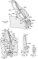
- Figure 2 is illustrated a pick 10A having a dog-leg bore, comprising a first bore part 13A located principally in the head 9A, and in communication with a second bore part 13B located principally within the shank 12A.
- a leading side 26 of the pick experiences tensile stresses upon being forced into the mineral being won, and a trailing side 27 of the pick experiences compressive stresses, and in accordance with the second aspect of the invention, at least the bore part 13B is provided in the compressive stress side of the shank.
- FIG. 2 Also illustrated in Figure 2 is a second embodiment of lance/mounting in which the requirement for the tapped socket 17 of the Figure 1 embodiment is eliminated.
- the lance 20A is of flexible, self-supporting tubing e.g., of nylon (trade mark).
- a plain hole 17A is provided and the mounting adaptor 18A is of metal or synthetic plastics and is a push-fit into the hole 17A, having an annular surface 28 seating on a radial end face 29 of the vane 2.
- the adaptor 18A has an inner end 30, of reduced diameter, engaging a portion of a water seal 31.
- the adaptor 18A is retained in its socket 17A against the action of the water pressure by an inner portion 32 of the shank 12A abutting the adaptor 18A, with an industry standard latching means 33, thus serving not only to latch the pick 10A releasably within its holder 4, but also to retain the adaptor 18A within its socket 17A.
- the adaptor 18B e.g. of nylon, is formed integrally with the lance 20B e.g., by injection moulding, with an enlarged portion 34 of the adaptor 18B manoeuvrable into a cup-like housing 35 secured by weld metal 36 in the inward extension 16, with a water seal 31A located between the enlarged portion 34 and the housing 35, the latter also being provided with a water inlet port 37 in fluid flow communication with a water supply bore 38 provided in the vane 2 and connected to a source of pressurised water.
- the adaptor 18C of the lance 20C is provided with an extension portion 39 in engagement with the inner portion 32 of the shank 12A of the pick 10A, to provide additional means of retaining this adaptor in position.
- the adaptor 18D is again illustrated as integral with its lance 20D being located within a cup-like housing 35A by means of a "U"-shaped staple 40 engaging both an external groove in the adaptor 18D and an internal groove in the housing 35A. Additional retention of the adaptor 18D against water pressure may be provided by the inner portion 32 of the shank 12A, or in an alternative embodiment, where no such secondary retention is required, then as indicated at 32A, the inner portion of the shank may be spaced from the adaptor 18D.
- FIG. 6 and 7 illustrates an arrangement of rotary cutting head 1A suitable for a roadheader type of machine i.e. a pick holder 4A is secured by weld metal 5 directly to the external periphery of the cutting head 1A, in contrast to being welded to a helical vane as shown in the embodiments of Figures 1 to 5.
- firstly aperture 6A and shank 12B of pick 10B are frusto-conical and secondly no bore 13, 13A, 13B, is provided in the pick shank 12B, but bore 13C is provided in the pick head 9B.
- One lance end is sealingly secured to a radially located adaptor 18E which makes a double-threaded connection with the cutting head 1A, the lance 20E being curved from its radial mounting to a tangential location.
- pick holder 4B is again welded to the external periphery of a cutting head 1B suitable for a roadheader type of machine, with a cup-like housing 35A welded to the pick holder 4B, while the adaptor 18C and lance 20C are of the form shown in Figure 4, with inner portion 32B of an extension 41 of the shank '12C of pick 10C in engagement with the adaptor 18C.
- a slot 42 is sawn into rectangular shank 12D of pick 10D, which slot is in communication with bore part 13A.
- the lance 20F is of nylon tube, with outer, burst-resistant braid.
- Adaptor 18F is locatable within the cup-like housing 35B, as described in connection with Figure 3.
- bore part 13B is drilled along the compressive stress side 27 of the shank 12A of pick 10E, parallel to the longitudinal axis of the shank 12A.
- a single bore 13D is drilled angularly through both the head 9A and shank 12A of pick 10F.
- a bore part 13E is drilled along the neutral axis of the shank 12A of pick 10G, to insert bore part 13A of the head 9A, while an alternative industry standard latching mens is indicated at 33A.
- lance 20G is provided externally, over a portion of its lenth extending from its adaptor 18F, with a coil spring protective sheath 43 serving not only to protect the lance 20G, of nylon for example, from any damage during pick insertion, but also to increase the self-supporting action of the lance 20G.
- a female pick 10H having a frusto-conical aperture 44 mounted on a male holder 4C having a corresponding frusto-conical projection 45 of an embodiment 1C of cutting head.
- the adaptor 18G is releasably retained by a "V"-shaped staple 40, with a water seal 31B, while the holder 4C is provided with a lance-accommodating bore part 13D.
Landscapes
- Engineering & Computer Science (AREA)
- Mining & Mineral Resources (AREA)
- Mechanical Engineering (AREA)
- Life Sciences & Earth Sciences (AREA)
- General Life Sciences & Earth Sciences (AREA)
- Geochemistry & Mineralogy (AREA)
- Geology (AREA)
- Earth Drilling (AREA)
- Perforating, Stamping-Out Or Severing By Means Other Than Cutting (AREA)
- Processing Of Stones Or Stones Resemblance Materials (AREA)
Priority Applications (1)
| Application Number | Priority Date | Filing Date | Title |
|---|---|---|---|
| AT85303118T ATE35716T1 (de) | 1984-05-04 | 1985-05-02 | Gesteinsloesewerkzeug, wasserzufuhrlanze und schneidpicke. |
Applications Claiming Priority (6)
| Application Number | Priority Date | Filing Date | Title |
|---|---|---|---|
| GB848411527A GB8411527D0 (en) | 1984-05-04 | 1984-05-04 | Rotary mineral cutting head |
| GB8411527 | 1984-05-04 | ||
| GB848421268A GB8421268D0 (en) | 1984-08-22 | 1984-08-22 | Rotary mineral cutting heads |
| GB8421268 | 1984-08-22 | ||
| GB858508629A GB8508629D0 (en) | 1985-04-02 | 1985-04-02 | Mineral cutter pick |
| GB8508629 | 1985-04-02 |
Publications (2)
| Publication Number | Publication Date |
|---|---|
| EP0167236A1 true EP0167236A1 (fr) | 1986-01-08 |
| EP0167236B1 EP0167236B1 (fr) | 1988-07-13 |
Family
ID=27262351
Family Applications (1)
| Application Number | Title | Priority Date | Filing Date |
|---|---|---|---|
| EP85303118A Expired EP0167236B1 (fr) | 1984-05-04 | 1985-05-02 | Outil de coupage de minéraux, lance d'amenée d'eau et pic de coupage |
Country Status (4)
| Country | Link |
|---|---|
| US (1) | US4652056A (fr) |
| EP (1) | EP0167236B1 (fr) |
| AU (1) | AU4196385A (fr) |
| DE (1) | DE3563768D1 (fr) |
Cited By (1)
| Publication number | Priority date | Publication date | Assignee | Title |
|---|---|---|---|---|
| EP0234793A1 (fr) * | 1986-02-19 | 1987-09-02 | Minnovation Limited | Pic de coup de minéraux et pointe de pic |
Families Citing this family (10)
| Publication number | Priority date | Publication date | Assignee | Title |
|---|---|---|---|---|
| FR2650973B1 (fr) * | 1989-08-17 | 1991-12-06 | Europ Propulsion | Procede et dispositif de decoupe au jet d'eau a haute pression de nappes epaisses de matiere souple |
| US6485104B1 (en) * | 2000-11-22 | 2002-11-26 | Kennametal Inc. | Cutting tool assembly with replaceable spray nozzle housing |
| EP1653009A1 (fr) * | 2004-10-26 | 2006-05-03 | Ihc Holland N.V. | Elément de coupe pour drague |
| US20100237684A1 (en) * | 2008-09-23 | 2010-09-23 | Kennametal Inc. | Core Breaker With Dust Suppression System |
| NL2007488C2 (en) | 2011-09-28 | 2013-04-02 | Ihc Holland Ie Bv | Cutting device. |
| RU2666906C2 (ru) * | 2013-06-18 | 2018-09-13 | Эско Корпорейшн | Резец для добычи полезных ископаемых, резцедержатель и их комбинация |
| CN103410509B (zh) * | 2013-08-29 | 2016-08-10 | 安庆市灵宝机械有限责任公司 | 一种便于安装截齿座及其组件 |
| US11702890B2 (en) * | 2021-01-06 | 2023-07-18 | Baker Hughes Oilfield Operations Llc | Earth-boring tools, cutting elements, and associated structures, apparatus, and methods |
| CN116025371B (zh) * | 2023-02-24 | 2023-09-29 | 山西潞安环保能源开发股份有限公司 | 一种岩巷小断面快速掘进机 |
| CN117506961B (zh) * | 2024-01-04 | 2024-03-08 | 欧特威(江苏)机械科技有限公司 | 一种掘进机截齿自动更换机械手及使用方法 |
Citations (5)
| Publication number | Priority date | Publication date | Assignee | Title |
|---|---|---|---|---|
| DE1283777B (de) * | 1967-11-22 | 1968-11-28 | Austin Hoy And Company Ltd Sta | Auswechselbare Schraemmeissel mit Meisselhalter und mit Zufuehrungen fuer Fluessigkeit |
| DE2210282A1 (de) * | 1971-03-12 | 1972-09-14 | Coal Industry (Patents) Ltd , London | Staubbekampfungsvornchtung für berg mannische Hereingewinnungsmaschinen |
| FR2408030A1 (fr) * | 1977-11-08 | 1979-06-01 | Gewerk Eisenhuette Westfalia | Couteau pour rabot a charbon et rabot garni de couteaux de ce type |
| GB2041043A (en) * | 1979-01-31 | 1980-09-03 | Eickhoff Geb | Improvements Relating to Mineral Mining Tools |
| EP0052977A2 (fr) * | 1980-11-24 | 1982-06-02 | PADLEY & VENABLES LIMITED | Dispositif composé d'un pic et de son support, pic et support d'un tel dispositif |
Family Cites Families (7)
| Publication number | Priority date | Publication date | Assignee | Title |
|---|---|---|---|---|
| FR1368318A (fr) * | 1963-06-20 | 1964-07-31 | Charbonnages De France | Pic d'abattage perfectionné |
| FR1387237A (fr) * | 1963-12-17 | 1965-01-29 | Charbonnages De France | Dispositif perfectionné de fixation d'outils d'abattage de minerai du genre pic de havage |
| GB1309005A (en) * | 1970-07-24 | 1973-03-07 | Coal Industry Patents Ltd | Rotary cutters for mineral mining machines |
| US4219239A (en) * | 1978-10-30 | 1980-08-26 | Krampe & Co. | Mining auger |
| GB2142064B (en) * | 1980-11-24 | 1985-08-29 | Padley & Venables Ltd | Holder for mineral-mining pick |
| GB2142676B (en) * | 1980-11-24 | 1985-08-29 | Padley & Venables Ltd | A pick, a holder for a pick, and the combination of a pick and a holder |
| GB2104945A (en) * | 1981-09-04 | 1983-03-16 | Green And Bingham Limited | Dusting suppressing mineral mining cutter head |
-
1985
- 1985-05-02 US US06/730,668 patent/US4652056A/en not_active Expired - Fee Related
- 1985-05-02 EP EP85303118A patent/EP0167236B1/fr not_active Expired
- 1985-05-02 DE DE8585303118T patent/DE3563768D1/de not_active Expired
- 1985-05-03 AU AU41963/85A patent/AU4196385A/en not_active Abandoned
Patent Citations (5)
| Publication number | Priority date | Publication date | Assignee | Title |
|---|---|---|---|---|
| DE1283777B (de) * | 1967-11-22 | 1968-11-28 | Austin Hoy And Company Ltd Sta | Auswechselbare Schraemmeissel mit Meisselhalter und mit Zufuehrungen fuer Fluessigkeit |
| DE2210282A1 (de) * | 1971-03-12 | 1972-09-14 | Coal Industry (Patents) Ltd , London | Staubbekampfungsvornchtung für berg mannische Hereingewinnungsmaschinen |
| FR2408030A1 (fr) * | 1977-11-08 | 1979-06-01 | Gewerk Eisenhuette Westfalia | Couteau pour rabot a charbon et rabot garni de couteaux de ce type |
| GB2041043A (en) * | 1979-01-31 | 1980-09-03 | Eickhoff Geb | Improvements Relating to Mineral Mining Tools |
| EP0052977A2 (fr) * | 1980-11-24 | 1982-06-02 | PADLEY & VENABLES LIMITED | Dispositif composé d'un pic et de son support, pic et support d'un tel dispositif |
Cited By (1)
| Publication number | Priority date | Publication date | Assignee | Title |
|---|---|---|---|---|
| EP0234793A1 (fr) * | 1986-02-19 | 1987-09-02 | Minnovation Limited | Pic de coup de minéraux et pointe de pic |
Also Published As
| Publication number | Publication date |
|---|---|
| US4652056A (en) | 1987-03-24 |
| AU4196385A (en) | 1985-11-07 |
| EP0167236B1 (fr) | 1988-07-13 |
| DE3563768D1 (en) | 1988-08-18 |
Similar Documents
| Publication | Publication Date | Title |
|---|---|---|
| CA1307299C (fr) | Trepan tranchant resistant a l'erosion possedant un rechargement dur | |
| AU686765B2 (en) | Rotatable cutting bit assembly | |
| US4652056A (en) | Mineral cutting device | |
| AU731941B2 (en) | Point attack tooling system for mineral winning | |
| EP0193268B1 (fr) | Pic de coupe pour minéraux | |
| CA2305235C (fr) | Appareil de forage directionnel | |
| US6851758B2 (en) | Rotatable bit having a resilient retainer sleeve with clearance | |
| IE50845B1 (en) | Drill tool | |
| US4280735A (en) | Non-rotary mining cutter with recessed nozzle insert | |
| US5378048A (en) | Spray nozzle for mining | |
| CN112585333A (zh) | 带有弯曲的泥浆沟槽的钻头 | |
| US7318490B2 (en) | Connection design and sonde housing assembly for a directional drill | |
| US5007684A (en) | Water spray unit for mining | |
| US6257672B1 (en) | Clip for retaining a water spray nozzle within a pick box of a cutting head | |
| EP1238181B1 (fr) | Ensemble fleuret-mandrin verrouillable | |
| CA2056804C (fr) | Equipement d'extraction de minerai, etc. | |
| US20130213717A1 (en) | Stepped drill bit assembly | |
| GB2365042A (en) | Pick box for housing a mineral cutter pick | |
| GB2144787A (en) | Mineral cutter pick and box combination and rotary cutting head incorporating same | |
| CN223018564U (zh) | 一种斜面开孔工装及用于tbm护盾外隧道斜面开孔的装置 | |
| GB2117675A (en) | Water spray nozzle | |
| AU6782081A (en) | Drill tool | |
| JP2000186483A (ja) | 掘削工具および掘削工法 | |
| HK1213310A1 (zh) | 挖掘工具 | |
| HK1213310B (en) | Digging tool |
Legal Events
| Date | Code | Title | Description |
|---|---|---|---|
| PUAI | Public reference made under article 153(3) epc to a published international application that has entered the european phase |
Free format text: ORIGINAL CODE: 0009012 |
|
| AK | Designated contracting states |
Designated state(s): AT BE CH DE FR GB IT LI LU NL SE |
|
| 17P | Request for examination filed |
Effective date: 19860630 |
|
| 17Q | First examination report despatched |
Effective date: 19870318 |
|
| D17Q | First examination report despatched (deleted) | ||
| GRAA | (expected) grant |
Free format text: ORIGINAL CODE: 0009210 |
|
| AK | Designated contracting states |
Kind code of ref document: B1 Designated state(s): AT BE CH DE FR GB IT LI LU NL SE |
|
| PG25 | Lapsed in a contracting state [announced via postgrant information from national office to epo] |
Ref country code: SE Effective date: 19880713 Ref country code: NL Effective date: 19880713 Ref country code: LI Effective date: 19880713 Ref country code: IT Free format text: LAPSE BECAUSE OF FAILURE TO SUBMIT A TRANSLATION OF THE DESCRIPTION OR TO PAY THE FEE WITHIN THE PRESCRIBED TIME-LIMIT;WARNING: LAPSES OF ITALIAN PATENTS WITH EFFECTIVE DATE BEFORE 2007 MAY HAVE OCCURRED AT ANY TIME BEFORE 2007. THE CORRECT EFFECTIVE DATE MAY BE DIFFERENT FROM THE ONE RECORDED. Effective date: 19880713 Ref country code: FR Free format text: THE PATENT HAS BEEN ANNULLED BY A DECISION OF A NATIONAL AUTHORITY Effective date: 19880713 Ref country code: CH Effective date: 19880713 Ref country code: BE Effective date: 19880713 Ref country code: AT Effective date: 19880713 |
|
| REF | Corresponds to: |
Ref document number: 35716 Country of ref document: AT Date of ref document: 19880715 Kind code of ref document: T |
|
| REF | Corresponds to: |
Ref document number: 3563768 Country of ref document: DE Date of ref document: 19880818 |
|
| REG | Reference to a national code |
Ref country code: CH Ref legal event code: PL |
|
| EN | Fr: translation not filed | ||
| NLV1 | Nl: lapsed or annulled due to failure to fulfill the requirements of art. 29p and 29m of the patents act | ||
| PLBE | No opposition filed within time limit |
Free format text: ORIGINAL CODE: 0009261 |
|
| STAA | Information on the status of an ep patent application or granted ep patent |
Free format text: STATUS: NO OPPOSITION FILED WITHIN TIME LIMIT |
|
| PG25 | Lapsed in a contracting state [announced via postgrant information from national office to epo] |
Ref country code: LU Free format text: LAPSE BECAUSE OF NON-PAYMENT OF DUE FEES Effective date: 19890531 |
|
| 26N | No opposition filed | ||
| PGFP | Annual fee paid to national office [announced via postgrant information from national office to epo] |
Ref country code: GB Payment date: 19900419 Year of fee payment: 6 |
|
| PG25 | Lapsed in a contracting state [announced via postgrant information from national office to epo] |
Ref country code: GB Effective date: 19910502 |
|
| GBPC | Gb: european patent ceased through non-payment of renewal fee | ||
| PGFP | Annual fee paid to national office [announced via postgrant information from national office to epo] |
Ref country code: DE Payment date: 19920422 Year of fee payment: 8 |
|
| PG25 | Lapsed in a contracting state [announced via postgrant information from national office to epo] |
Ref country code: DE Effective date: 19940201 |