EP0167276A1 - Dispositif de verrouillage - Google Patents
Dispositif de verrouillage Download PDFInfo
- Publication number
- EP0167276A1 EP0167276A1 EP85303841A EP85303841A EP0167276A1 EP 0167276 A1 EP0167276 A1 EP 0167276A1 EP 85303841 A EP85303841 A EP 85303841A EP 85303841 A EP85303841 A EP 85303841A EP 0167276 A1 EP0167276 A1 EP 0167276A1
- Authority
- EP
- European Patent Office
- Prior art keywords
- key
- valve
- rotatable
- members
- drive
- Prior art date
- Legal status (The legal status is an assumption and is not a legal conclusion. Google has not performed a legal analysis and makes no representation as to the accuracy of the status listed.)
- Granted
Links
- 230000007246 mechanism Effects 0.000 title claims abstract description 71
- 230000000452 restraining effect Effects 0.000 claims abstract description 3
- 230000000630 rising effect Effects 0.000 claims description 23
- 238000000926 separation method Methods 0.000 claims description 5
- 230000000694 effects Effects 0.000 claims description 2
- 230000000717 retained effect Effects 0.000 claims 1
- 239000012530 fluid Substances 0.000 abstract 1
- 238000009434 installation Methods 0.000 description 4
- 230000002401 inhibitory effect Effects 0.000 description 2
- 238000003754 machining Methods 0.000 description 2
- 230000004048 modification Effects 0.000 description 2
- 238000012986 modification Methods 0.000 description 2
- 125000006850 spacer group Chemical group 0.000 description 2
- 238000010348 incorporation Methods 0.000 description 1
- 230000002093 peripheral effect Effects 0.000 description 1
- 238000012163 sequencing technique Methods 0.000 description 1
Images




Classifications
-
- F—MECHANICAL ENGINEERING; LIGHTING; HEATING; WEAPONS; BLASTING
- F16—ENGINEERING ELEMENTS AND UNITS; GENERAL MEASURES FOR PRODUCING AND MAINTAINING EFFECTIVE FUNCTIONING OF MACHINES OR INSTALLATIONS; THERMAL INSULATION IN GENERAL
- F16K—VALVES; TAPS; COCKS; ACTUATING-FLOATS; DEVICES FOR VENTING OR AERATING
- F16K35/00—Means to prevent accidental or unauthorised actuation
- F16K35/06—Means to prevent accidental or unauthorised actuation using a removable actuating or locking member, e.g. a key
Definitions
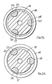
- an interlock mechanism for a plurality of rotatable members is characterised by the provision of means mounting the plurality of members with their axes parallel on a common pitch circle each for turning movement about its own respective axis, a plurality of cams one associated with each rotatable member respectively and each cam having a base portion and a lobe portion, and a ring carried by the mounting means to surround with clearance all of the cams when turned to have their respective lobes directed inwardly of the common pitch circle, the circumferential length of the ring being such that when any one of the rotatable members is turned to engage the lobe of its associated cam with the ring, the ring is moved laterally nearer the base portions of the other cams so restraining the rotation of the other rotatable members associated with those said other cams, thereof.
- any selected one rotatable member may be turned from its base or datum position, but when so turned, all of the other members are restrained from being turned from their respective base or datum positions.
- These base or datum positions are defined by the base of each respective cam facing the laterally movable ring.
- the associated detent member may be maintained in the recess in the key member by means of a sleeve element located in the axial bore but of a greater outer diameter than the rising stem, the sleeve element being lifted clear of the detent member by the rising stem as the latter rises to its fully opened position; this then permits the detent member to move radially into the bore, so freeing the key member for rotation.
- the main body 18 of the valve lock mechanism is of generally cylindrical shape, and has an axial through- bore 19 with several sections of different diameters.
- the lower end portion of the axial bore 19 is of relatively large diameter and the drive disc 12 is rotatably received therein.
- These two components are restrained against axial separation by means of four balls 20 mounted in radial bores 21 in the portion of the main body 18 which surrounds the drive disc 12, such that the balls are located partly in the bores and partly in the peripheral groove 15 of the drive disc 12.
- the four balls are maintained in this position by a sleeve 22 which is fitted around the main body 18, the sleeve being held at the required position by means of a bolt 23 threaded into the main body and having its head located in an aperture in the sleeve 22.
- This bolt 23 is preferably of the security variety, and so may be removed only by an operator having an appropriately- configured key, rather than a conventional spanner. Once removed, the sleeve 22 may be raised upwardly so bringing the skirt 24 of the sleeve, which has an increased internal diameter, into register with the region of the main body carrying the balls 20, so that the balls may move radially outwardly and hence permit the main body 18 to be lifted clear of the drive disc 12.
- each member 26, 27 and 28 there is provided a chordal flat 33, 34 and 35 respectively, such that each member has in effect a cam profile with the chordal flat serving as the base portion of the cam, and the arcuate outer surface of the member serving as the cam lobe.
- the drive connection member 26 has a further cam formed at its lowermost end, again by machining a chordal flat 36 into the end portion of the drive connection member, the flat 36 being diametrically opposed to flat 33.
- the lock mechanism as described above is assembled in such a way that the configuration of Figure 7A can be achieved only when both keys are engaged with their respective drive members and appropriately turned; then the drive connection member 26 may be turned to connect the main body 18 and the disc 12.
- the valve may be operated, by applying drive to the bars 63, so turning the drive disc 12 either fully to open the valve or fully to close it.
- the drive connection member may release the main body 18 from the drive disc 12 at any intermediate setting of the valve, neither key member 27 or 28 may be turned to release its key at any such intermediate setting.
- the drive connection member 26 may be turned to free the ring 48, which then permits either key member 27 or 28 to be turned.
- only one of those key members may be turned at either extreme setting of the valve, by virtue of the interlock provided by the balls 52 or 56, operating in conjunction with the movement of the valve stem 11.
- a drive connection member 88 and two key members 89 Rotatably mounted in the body 84 are a drive connection member 88 and two key members 89, these being generally similar to the corresponding members 26, 27 and 28 of the first embodiment.
- Each member 88 and 89 has a flat 90 which co-operates with a ring 91, as shown in Figure 10, such that only one of the members may be turned at any one time from the position shown in Figure 10.
- a circlip 92 is arranged to retain the members 88 and 89 in position, and to impart friction thereto, so as to prevent inadvertent rotation thereof.
Landscapes
- Engineering & Computer Science (AREA)
- General Engineering & Computer Science (AREA)
- Mechanical Engineering (AREA)
- Preventing Unauthorised Actuation Of Valves (AREA)
- Arrangement Or Mounting Of Control Devices For Change-Speed Gearing (AREA)
- Switches With Compound Operations (AREA)
Priority Applications (1)
| Application Number | Priority Date | Filing Date | Title |
|---|---|---|---|
| AT85303841T ATE41494T1 (de) | 1984-06-02 | 1985-05-31 | Verriegelungsvorrichtung. |
Applications Claiming Priority (2)
| Application Number | Priority Date | Filing Date | Title |
|---|---|---|---|
| GB848414133A GB8414133D0 (en) | 1984-06-02 | 1984-06-02 | Interlock mechanisms |
| GB8414133 | 1984-06-02 |
Publications (2)
| Publication Number | Publication Date |
|---|---|
| EP0167276A1 true EP0167276A1 (fr) | 1986-01-08 |
| EP0167276B1 EP0167276B1 (fr) | 1989-03-15 |
Family
ID=10561871
Family Applications (1)
| Application Number | Title | Priority Date | Filing Date |
|---|---|---|---|
| EP85303841A Expired EP0167276B1 (fr) | 1984-06-02 | 1985-05-31 | Dispositif de verrouillage |
Country Status (4)
| Country | Link |
|---|---|
| EP (1) | EP0167276B1 (fr) |
| AT (1) | ATE41494T1 (fr) |
| DE (1) | DE3568851D1 (fr) |
| GB (1) | GB8414133D0 (fr) |
Cited By (1)
| Publication number | Priority date | Publication date | Assignee | Title |
|---|---|---|---|---|
| EP0375475A1 (fr) * | 1988-12-23 | 1990-06-27 | Les Robinets Presto Société Anonyme | Dispositif de sécurité pour assembler les deux parties d'un corps de robinet |
Families Citing this family (2)
| Publication number | Priority date | Publication date | Assignee | Title |
|---|---|---|---|---|
| DE202007011948U1 (de) * | 2007-08-28 | 2007-11-08 | Haake Technik Gmbh | Ventilverriegelungssystem |
| DE202010009521U1 (de) * | 2010-06-25 | 2011-10-05 | Gebr. Kemper Gmbh + Co. Kg Metallwerke | Bediengriff einer Armatur |
Citations (2)
| Publication number | Priority date | Publication date | Assignee | Title |
|---|---|---|---|---|
| US2439113A (en) * | 1944-07-15 | 1948-04-06 | Bendix Aviat Corp | Valve controlling mechanism |
| EP0068841A1 (fr) * | 1981-06-25 | 1983-01-05 | Alan Elgar Herbert Ellis | Mécanisme d'embrayage spécialement approprié aux poignées de valves |
Family Cites Families (2)
| Publication number | Priority date | Publication date | Assignee | Title |
|---|---|---|---|---|
| GB2045855B (en) * | 1979-03-24 | 1982-11-17 | Ellis A E H | Key holder |
| GB2105442B (en) * | 1981-09-08 | 1985-07-10 | Alan Elgar Herbert Ellis | Security device for a rising stem valve |
-
1984
- 1984-06-02 GB GB848414133A patent/GB8414133D0/en active Pending
-
1985
- 1985-05-31 DE DE8585303841T patent/DE3568851D1/de not_active Expired
- 1985-05-31 AT AT85303841T patent/ATE41494T1/de active
- 1985-05-31 EP EP85303841A patent/EP0167276B1/fr not_active Expired
Patent Citations (2)
| Publication number | Priority date | Publication date | Assignee | Title |
|---|---|---|---|---|
| US2439113A (en) * | 1944-07-15 | 1948-04-06 | Bendix Aviat Corp | Valve controlling mechanism |
| EP0068841A1 (fr) * | 1981-06-25 | 1983-01-05 | Alan Elgar Herbert Ellis | Mécanisme d'embrayage spécialement approprié aux poignées de valves |
Cited By (2)
| Publication number | Priority date | Publication date | Assignee | Title |
|---|---|---|---|---|
| EP0375475A1 (fr) * | 1988-12-23 | 1990-06-27 | Les Robinets Presto Société Anonyme | Dispositif de sécurité pour assembler les deux parties d'un corps de robinet |
| FR2641052A1 (fr) * | 1988-12-23 | 1990-06-29 | Presto Robinets Sa |
Also Published As
| Publication number | Publication date |
|---|---|
| GB8414133D0 (en) | 1984-07-04 |
| ATE41494T1 (de) | 1989-04-15 |
| DE3568851D1 (en) | 1989-04-20 |
| EP0167276B1 (fr) | 1989-03-15 |
Similar Documents
| Publication | Publication Date | Title |
|---|---|---|
| US4126023A (en) | Tamperproof locking and latching mechanism for rotatable controls | |
| US4723569A (en) | Lock mechanisms | |
| US5014528A (en) | Tamper-proof locking mechanism for quarter turn valves | |
| CA2014120C (fr) | Rbonet et dispositif de verrouillage connexe | |
| EP3279505B1 (fr) | Pivot | |
| US4619437A (en) | Adjustable torque limiting valve handle | |
| NZ216420A (en) | Replacement top for screw down tap: adjustment nut allows axial adjustment in permanent sealing of tap assembly to seat in tap body | |
| CA2179850A1 (fr) | Prolongement de poignee inviolable pour robinets quart-de-tour | |
| EP0189265B1 (fr) | Mécanisme d'actionnement verrouillable | |
| EP0167276B1 (fr) | Dispositif de verrouillage | |
| CA2025065C (fr) | Soupape d'interdiction, avec systeme de controle de remise en marche | |
| US4614203A (en) | Lockable valve | |
| US4450697A (en) | Security devices for rotatable members and fluid flow control valves incorporating such devices | |
| US7178781B2 (en) | Valve or tap for fluids with locking device | |
| EP0168154A2 (fr) | Dispositif de verrouillage | |
| EP0073862B1 (fr) | Dispositif de sécurité pour des éléments tournantes et obturateurs de commande de fluide équipés d'un tel dispositif | |
| GB2292207A (en) | Locking mechanism for a valve | |
| EP0068841B1 (fr) | Mécanisme d'embrayage spécialement approprié aux poignées de valves | |
| US20020047102A1 (en) | Adjustable stop apparatus | |
| US6105484A (en) | Lockout device for valve actuators | |
| EP1380783A1 (fr) | Mecanisme de blocage pour soupape | |
| JP2005180529A (ja) | バルブのロック装置 | |
| GB2026134A (en) | A rotary control attachment for a valve | |
| US3344683A (en) | Actuating means adapter for quarterturn valves | |
| CA1170640A (fr) | Dispositif de surete sur mecanisme tournants, et distributeurs hydrauliques garnis dudit dispositif |
Legal Events
| Date | Code | Title | Description |
|---|---|---|---|
| PUAI | Public reference made under article 153(3) epc to a published international application that has entered the european phase |
Free format text: ORIGINAL CODE: 0009012 |
|
| AK | Designated contracting states |
Designated state(s): AT BE CH DE FR GB IT LI LU NL SE |
|
| 17P | Request for examination filed |
Effective date: 19860702 |
|
| 17Q | First examination report despatched |
Effective date: 19870715 |
|
| GRAA | (expected) grant |
Free format text: ORIGINAL CODE: 0009210 |
|
| AK | Designated contracting states |
Kind code of ref document: B1 Designated state(s): AT BE CH DE FR GB IT LI LU NL SE |
|
| REF | Corresponds to: |
Ref document number: 41494 Country of ref document: AT Date of ref document: 19890415 Kind code of ref document: T |
|
| REF | Corresponds to: |
Ref document number: 3568851 Country of ref document: DE Date of ref document: 19890420 |
|
| REG | Reference to a national code |
Ref country code: CH Ref legal event code: PUE Owner name: ELLIS INTEGRAL VALVE LOCKS LIMITED |
|
| PGFP | Annual fee paid to national office [announced via postgrant information from national office to epo] |
Ref country code: SE Payment date: 19890530 Year of fee payment: 5 Ref country code: LU Payment date: 19890530 Year of fee payment: 5 Ref country code: FR Payment date: 19890530 Year of fee payment: 5 |
|
| ITTA | It: last paid annual fee | ||
| PG25 | Lapsed in a contracting state [announced via postgrant information from national office to epo] |
Ref country code: LU Free format text: LAPSE BECAUSE OF NON-PAYMENT OF DUE FEES Effective date: 19890531 |
|
| PGFP | Annual fee paid to national office [announced via postgrant information from national office to epo] |
Ref country code: CH Payment date: 19890531 Year of fee payment: 5 |
|
| ITF | It: translation for a ep patent filed | ||
| PGFP | Annual fee paid to national office [announced via postgrant information from national office to epo] |
Ref country code: AT Payment date: 19890614 Year of fee payment: 5 |
|
| ET | Fr: translation filed | ||
| PGFP | Annual fee paid to national office [announced via postgrant information from national office to epo] |
Ref country code: BE Payment date: 19890809 Year of fee payment: 5 |
|
| DIN2 | Information on inventor provided after grant (deleted) | ||
| REG | Reference to a national code |
Ref country code: FR Ref legal event code: TP |
|
| RAP2 | Party data changed (patent owner data changed or rights of a patent transferred) |
Owner name: ELLIS INTEGRAL VALVE LOCKS LIMITED |
|
| RIN2 | Information on inventor provided after grant (corrected) |
Free format text: ELLIS, ALAN ELGAR HERBERT |
|
| NLT2 | Nl: modifications (of names), taken from the european patent patent bulletin |
Owner name: ELLIS INTEGRAL VALVE LOCKS LIMITED TE LONDEN, GROO |
|
| PLBE | No opposition filed within time limit |
Free format text: ORIGINAL CODE: 0009261 |
|
| STAA | Information on the status of an ep patent application or granted ep patent |
Free format text: STATUS: NO OPPOSITION FILED WITHIN TIME LIMIT |
|
| 26N | No opposition filed | ||
| NLS | Nl: assignments of ep-patents |
Owner name: ELLIS INTEGRAL VALVE LOCKS LIMITED TE LONDEN, GROO |
|
| PG25 | Lapsed in a contracting state [announced via postgrant information from national office to epo] |
Ref country code: LI Effective date: 19900531 Ref country code: CH Effective date: 19900531 Ref country code: BE Effective date: 19900531 Ref country code: AT Effective date: 19900531 |
|
| PGFP | Annual fee paid to national office [announced via postgrant information from national office to epo] |
Ref country code: NL Payment date: 19900531 Year of fee payment: 6 |
|
| PG25 | Lapsed in a contracting state [announced via postgrant information from national office to epo] |
Ref country code: SE Effective date: 19900601 |
|
| PGFP | Annual fee paid to national office [announced via postgrant information from national office to epo] |
Ref country code: DE Payment date: 19900615 Year of fee payment: 6 |
|
| BERE | Be: lapsed |
Owner name: ELLIS INTEGRAL VALVE LOCKS LTD Effective date: 19900531 |
|
| PG25 | Lapsed in a contracting state [announced via postgrant information from national office to epo] |
Ref country code: FR Effective date: 19910131 |
|
| REG | Reference to a national code |
Ref country code: CH Ref legal event code: PL |
|
| REG | Reference to a national code |
Ref country code: FR Ref legal event code: ST |
|
| PG25 | Lapsed in a contracting state [announced via postgrant information from national office to epo] |
Ref country code: NL Effective date: 19911201 |
|
| NLV4 | Nl: lapsed or anulled due to non-payment of the annual fee | ||
| PG25 | Lapsed in a contracting state [announced via postgrant information from national office to epo] |
Ref country code: DE Effective date: 19920303 |
|
| PGFP | Annual fee paid to national office [announced via postgrant information from national office to epo] |
Ref country code: GB Payment date: 19930519 Year of fee payment: 9 |
|
| PG25 | Lapsed in a contracting state [announced via postgrant information from national office to epo] |
Ref country code: GB Effective date: 19940531 |
|
| GBPC | Gb: european patent ceased through non-payment of renewal fee |
Effective date: 19940531 |
|
| EUG | Se: european patent has lapsed |
Ref document number: 85303841.2 Effective date: 19910211 |