EP0167302A2 - Circuits d'alimentation d'antennes - Google Patents
Circuits d'alimentation d'antennes Download PDFInfo
- Publication number
- EP0167302A2 EP0167302A2 EP85304020A EP85304020A EP0167302A2 EP 0167302 A2 EP0167302 A2 EP 0167302A2 EP 85304020 A EP85304020 A EP 85304020A EP 85304020 A EP85304020 A EP 85304020A EP 0167302 A2 EP0167302 A2 EP 0167302A2
- Authority
- EP
- European Patent Office
- Prior art keywords
- feed network
- phase
- network according
- waveguide section
- quarter
- Prior art date
- Legal status (The legal status is an assumption and is not a legal conclusion. Google has not performed a legal analysis and makes no representation as to the accuracy of the status listed.)
- Granted
Links
Images


Classifications
-
- H—ELECTRICITY
- H01—ELECTRIC ELEMENTS
- H01P—WAVEGUIDES; RESONATORS, LINES, OR OTHER DEVICES OF THE WAVEGUIDE TYPE
- H01P1/00—Auxiliary devices
- H01P1/18—Phase-shifters
- H01P1/182—Waveguide phase-shifters
-
- H—ELECTRICITY
- H01—ELECTRIC ELEMENTS
- H01P—WAVEGUIDES; RESONATORS, LINES, OR OTHER DEVICES OF THE WAVEGUIDE TYPE
- H01P1/00—Auxiliary devices
- H01P1/20—Frequency-selective devices, e.g. filters
- H01P1/207—Hollow waveguide filters
Definitions
- This invention relates to antenna feed networks and, in particular, feed networks for satellite antennas.
- phase shifters are of two types, namely inductive and capacitive, to ensure not only correct phase at midband but also to achieve equal phase slope among the many runs leading to the antenna horns.
- phase shifters are used in a typical communication satellite; for example, the G-STAR antenna has over a hundred phase shifters.
- phase shifter represents a major component in the overall cost of the feed network and the space occupied by the phase shifters significantly increases the size of the feed network.
- phase slope equalizer The novel device, known hereinafter as a phase slope equalizer, is placed in each run of the antenna.
- the phase slope equalizer comprises, in essence, a resonant circuit placed in a waveguide.
- the resonant circuit is a parallel resonant circuit comprising a pair of inductive posts with a capacitive tuning screw located between the posts.
- an inductive iris is used.
- the capacitive element is a tuning screw.
- a third embodiment is in the form of a resonant slot which replaces both the inductive posts and the capacitive tuning screw.
- the present invention may be summarized as a phase slope equalizer comprising a waveguide section containing a resonant circuit which has a substantially constant slope phase shift/frequency response curve extending from a positive phase shift through zero phase shift in the region of the midband frequency to a negative phase shift.
- the invention comprises a feed network for a microwave antenna of the type having a plurality of individual antenna components connected respectively to individual feed lines and sending or receiving signals in predetermined phase relationships to one another, the network including in each feed line a phase slope equalizer having a substantially constant slope phase shift/frequency response curve extending from a positive phase shift through zero phase shift in the region of the midband frequency to a negative phase shift, whereby the predetermined phase relationships are achieved without the necessity for separate phase shifters.
- FIGURE 1 The significance of the invention will be better understood after a brief review of a conventional prior art antenna feed network as shown in FIGURE 1.
- the antenna feed network comprises a horn array 2, a duplexer (also known as diplexer) array 4, a transmit network 6 and a receive network 8.
- the horn array 2 comprises a plurality (eight illustrated in this example) of individual horns 2a-2h all of which are positioned to direct individual radio frequency beams onto a reflector (not shown) which redirects a combined beam to the desired coverage area on earth.
- the duplexer array 4 simply provides a means for allowing the transmit 6 and receive 8 networks to share the same array of horns, and for the purposes of understanding the present invention, need not be described further herein.
- the transmit network 6 is similar in detailed construction and operation to the receive network 8 and, accordingly, only the transmit network will be described in greater detail.
- the transmit network 6 are a plurality of couplers 12 and phase shifters 14.
- the couplers 12 distribute power among the horns 2a-2h in a prescribed manner and the phase shifters 14 ensure the desired phase relationship among the horns. Although only one phase shifter 14 is shown in each feed line 16, in fact most of the lines would have two or more phase shifters.
- the phase shifters 14 used are of two types, capacitive and inductive. These give respectively negative and positive phase offsets. The phase offset however varies with frequency. Thus, if a 90° phase difference is required between two lines, a single 90° phase shifter placed in one of the lines will give the correct phase relationship at one frequency only, say at midband; there will be an error at the bandedges. To avoid this error, it is necessary to use a +45° phase shifter in one line and a -45° phase shifter in the other.
- the two phase shifters although having differing signs, both have the same phase slope. That is, a capacitive phase shifter having numerically the same phase offset at midband as that of an inductive phase shifter, will also have the same algebraic slope. In a typical feed therefore, combinations of different capacitive and inductive phase shifters are used throughout.
- phase slope equalizer a new component that has zero phase offset at midband but has a substantially constant phase slope across the bandwidth.
- Phase correction therefore becomes relatively simple.
- the path lengths of the various feed lines are arranged to give the required phase offsets at midband only and then phase slope equalizers (one per line) are introduced to equalize the slopes among the lines 16.
- the slopes of all these equalizers have the same sign. This new approach dispenses with the inductive and capacitive phase shifters 14.
- FIGURES 2(a) and 2(b) illustrate an example of the new phase slope equalizer 18. It comprises a rectangular section waveguide 20 across the smaller dimension of which extend two metal posts 22 which are both soldered to opposite faces 24 and 26 of the waveguide 20.
- a metal tuning screw 28 is received in a threaded hole (not shown) in face 26 of waveguide 20 and extends inwardly of the waveguide at a location intermediate the posts 22 and parallel thereto.
- a portion of screw 28 extends outwardly of the wave guide and is provided with a slot 30 which may be engaged by a screwdriver for moving the screw further inwardly or outwardly to increase or decrease the capacitance as necessary to tune the device to the midband frequency.
- FIGURE 3 is the equivalent diagram of the phase slope equalizer 18 of FIGURES 2(a) and 2(b). Essentially the device operates as a shunt resonator comprising an inductance L representing the inductance of the posts 22 and a variable capacitor C representing the variable capacitance of the tuning screw 28.
- phase shift/frequency response curve 32 is essentially a straight line passing through the midband frequency f 0 at zero phase offset, the slope of the line being negative, substantially constant and a function of L and C.
- FIGURE 5 When the circuit of FIGURE 3 is connected in a line it may be represented by FIGURE 5 in which jB represents the impedance of the shunt resonator, El is the input voltage . and E2 is the output voltage.
- ⁇ is not larger than 5°. This corres ponds to
- the return loss at the bandedge is 21.2 dB.
- the return loss can be improved by using two smaller elements, each giving half the slope, separated by quarter wave-length as shown in FIGURE 6.
- the waveguide, posts and screws are made of aluminum, the waveguide is 0.75" wide, the posts 0.062" in diameter and the screws 0.20" in diameter.
- the quarter wavelength distance between the elements corresponds to 0.328".
- Small phase slope can of course be compensated by a single element. Conversely in situations where larger than +5°/500 MHz slope is required, then 3- or 4- element designs could be used.
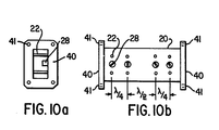
- each having twice the susceptance of that of the first (or last) element For designs with more than two elements it is preferred, for performance reasons, to have all the inner elements, each having twice the susceptance of that of the first (or last) element. For example, if the susceptance Bo of the first (or last) element is equal to 5, then all of the other elements should each have a susceptance of 10. The spacing between consecutive elements is quarter-wave at the midband.
- the first element and the last element each comprises a pair of spaced posts 22 and a tuning screw 28 of the type shown schematically in FIGURES 2(a) and 2(b).
- the second and third elements spaced from each other and from the first and last elements by a quarter wavelength, each comprises a pair of spaced posts 42 of greater diameter than posts 22 to provide an inductance twice that of posts 22 and a tuning screw 44 of greater length than screws 28 to provide a capacitance twice that of screws 28.
- FIGURE 10 showing a 4-element design can be used. This has the two inner elements spaced half-wave apart. In essence, the first two elements form a pair, whose centre is spaced three quarter-wave from the centre of the pair formed by the third and last elements. It is recommended, for designs with even more than 4 elements, that the former (i.e. every spacing is quarter-wave) be used.
- phase slope equalizer is shown in FIGURES 7(a) and 7(b).
- an inductive iris 36 is used instead of inductive posts.
- the iris is formed as a thin metal plate defining an aperture 37 into which extends the tuning screw 28.
- FIGURES 8(a) and 8(b) A further alternative is shown in FIGURES 8(a) and 8(b).
- the posts and tuning screw are replaced with a resonant slot 38 which resonates at the midband frequency.
- the embodiments using an inductive iris or resonant slot may be provided with two or more elemental resonant circuits.
- the same considerations regarding spacing and susceptance as discussed in relation to FIGURES 9 and 10 apply to the multi-element iris or resonant slot type.
- phase slope equalizer two basic embodiments have been described.
- the first is where the inner elements are identical but of double the susceptance of the first (and last) element.
- the second is where all the elements are identical but their separations are unequal.
- other distributions of element values i.e. unequal elements
- the separation between elements is essentially quarter-wave or multiples of quarter-wave.
Landscapes
- Variable-Direction Aerials And Aerial Arrays (AREA)
- Control Of Motors That Do Not Use Commutators (AREA)
Applications Claiming Priority (2)
| Application Number | Priority Date | Filing Date | Title |
|---|---|---|---|
| US06/618,446 US4633258A (en) | 1984-06-07 | 1984-06-07 | Phase slope equalizer |
| US618446 | 1984-06-07 |
Publications (3)
| Publication Number | Publication Date |
|---|---|
| EP0167302A2 true EP0167302A2 (fr) | 1986-01-08 |
| EP0167302A3 EP0167302A3 (en) | 1987-09-09 |
| EP0167302B1 EP0167302B1 (fr) | 1992-01-15 |
Family
ID=24477722
Family Applications (1)
| Application Number | Title | Priority Date | Filing Date |
|---|---|---|---|
| EP85304020A Expired - Lifetime EP0167302B1 (fr) | 1984-06-07 | 1985-06-06 | Circuits d'alimentation d'antennes |
Country Status (4)
| Country | Link |
|---|---|
| US (1) | US4633258A (fr) |
| EP (1) | EP0167302B1 (fr) |
| CA (1) | CA1234912A (fr) |
| DE (2) | DE3585178D1 (fr) |
Cited By (2)
| Publication number | Priority date | Publication date | Assignee | Title |
|---|---|---|---|---|
| EP0352685A1 (fr) * | 1988-07-28 | 1990-01-31 | Alcatel Telspace | Filtre large bande en guide d'onde |
| EP0533185A1 (fr) * | 1991-09-18 | 1993-03-24 | Fujitsu Limited | Filtre à guide d'ondes avec conversion de mode coaxiale/guide d'ondes |
Families Citing this family (4)
| Publication number | Priority date | Publication date | Assignee | Title |
|---|---|---|---|---|
| CA1260083A (fr) * | 1986-12-04 | 1989-09-26 | Chuck K. Mok | Egaliseur de pente de phase pour antennes de communication par satellite |
| US9007275B2 (en) | 2006-06-08 | 2015-04-14 | Fractus, S.A. | Distributed antenna system robust to human body loading effects |
| US10170831B2 (en) * | 2015-08-25 | 2019-01-01 | Elwha Llc | Systems, methods and devices for mechanically producing patterns of electromagnetic energy |
| CN116724465B (zh) * | 2020-12-28 | 2025-09-09 | 华为技术有限公司 | 基站天线 |
Family Cites Families (17)
| Publication number | Priority date | Publication date | Assignee | Title |
|---|---|---|---|---|
| US102002A (en) * | 1870-04-19 | Gheister l | ||
| US2461005A (en) * | 1940-04-05 | 1949-02-08 | Bell Telephone Labor Inc | Ultra high frequency transmission |
| US2642529A (en) * | 1949-07-29 | 1953-06-16 | Int Standard Electric Corp | Broadband loop antenna |
| US3275952A (en) * | 1950-05-29 | 1966-09-27 | Rca Corp | Microwave phase shifter system providing substantial constant phase shift over broad band |
| US2905940A (en) * | 1957-05-02 | 1959-09-22 | Edward G Spencer | Electromagnetically steered microwave antenna |
| US3153208A (en) * | 1960-05-06 | 1964-10-13 | Henry J Riblet | Waveguide filter having nonidentical sections resonant at same fundamental frequency and different harmonic frequencies |
| US3108237A (en) * | 1961-09-29 | 1963-10-22 | Hughes Aircraft Co | Variable microwave phase shifter having moveable reactive stubs |
| NL297026A (fr) * | 1962-08-24 | |||
| US3421118A (en) * | 1965-07-01 | 1969-01-07 | Bell Telephone Labor Inc | Adjustable phase equalizer |
| FR1460075A (fr) * | 1965-10-15 | 1966-06-17 | Thomson Houston Comp Francaise | Perfectionnements aux réseaux rayonnants |
| US3611400A (en) * | 1968-10-16 | 1971-10-05 | Tokyo Shibaura Electric Co | Phased array antenna |
| US3911442A (en) * | 1974-02-15 | 1975-10-07 | Raytheon Co | Constant beamwidth antenna |
| US3955161A (en) * | 1974-08-05 | 1976-05-04 | General Dynamics Corporation | Molded waveguide filter with integral tuning posts |
| GB1515533A (en) * | 1975-08-20 | 1978-06-28 | C S Antennas Ltd | Aerials |
| US4041421A (en) * | 1976-05-03 | 1977-08-09 | Gte Automatic Electric Laboratories Incorporated | Stabilized locking mechanism for threaded tuning screws in waveguides |
| UST102002I4 (en) | 1979-08-06 | 1982-07-06 | Phase invariant, adjustable power controller | |
| US4321568A (en) * | 1980-09-19 | 1982-03-23 | Bell Telephone Laboratories, Incorporated | Waveguide filter employing common phase plane coupling |
-
1984
- 1984-06-07 US US06/618,446 patent/US4633258A/en not_active Expired - Fee Related
-
1985
- 1985-06-05 CA CA000483180A patent/CA1234912A/fr not_active Expired
- 1985-06-06 EP EP85304020A patent/EP0167302B1/fr not_active Expired - Lifetime
- 1985-06-06 DE DE8585304020T patent/DE3585178D1/de not_active Expired - Fee Related
- 1985-06-06 DE DE198585304020T patent/DE167302T1/de active Pending
Cited By (4)
| Publication number | Priority date | Publication date | Assignee | Title |
|---|---|---|---|---|
| EP0352685A1 (fr) * | 1988-07-28 | 1990-01-31 | Alcatel Telspace | Filtre large bande en guide d'onde |
| FR2634949A1 (fr) * | 1988-07-28 | 1990-02-02 | Alcatel Thomson Faisceaux | Filtre large bande en guide d'onde |
| EP0533185A1 (fr) * | 1991-09-18 | 1993-03-24 | Fujitsu Limited | Filtre à guide d'ondes avec conversion de mode coaxiale/guide d'ondes |
| US5398009A (en) * | 1991-09-18 | 1995-03-14 | Fujitsu Limited | Waveguide filter with coaxial/waveguide mode conversion |
Also Published As
| Publication number | Publication date |
|---|---|
| DE167302T1 (de) | 1986-08-14 |
| CA1234912A (fr) | 1988-04-05 |
| DE3585178D1 (de) | 1992-02-27 |
| EP0167302A3 (en) | 1987-09-09 |
| EP0167302B1 (fr) | 1992-01-15 |
| US4633258A (en) | 1986-12-30 |
Similar Documents
| Publication | Publication Date | Title |
|---|---|---|
| EP0142555B1 (fr) | Reseau en phase a bande double utilisant un element a large bande avec un diplexeur | |
| DE68919323T2 (de) | Mikrostreifenantenne. | |
| US5539420A (en) | Multilayered, planar antenna with annular feed slot, passive resonator and spurious wave traps | |
| DE3784569T2 (de) | Mikrowellenantenne. | |
| US5010348A (en) | Device for exciting a waveguide with circular polarization from a plane antenna | |
| US5175560A (en) | Notch radiator elements | |
| US4375622A (en) | Multiport radio frequency signal combiner | |
| IE53573B1 (en) | Microwave receiving device | |
| EP0423114B1 (fr) | Multiplexeur de micro-ondes a filtre multimode | |
| US5136304A (en) | Electronically tunable phased array element | |
| US4620168A (en) | Coaxial type tunable hyperfrequency elimination band filter comprising of dielectric resonators | |
| US4868575A (en) | Phase slope equalizer for satellite antennas | |
| US5210543A (en) | Feed waveguide for an array antenna | |
| US4358770A (en) | Multiple frequency antenna feed system | |
| US4298878A (en) | Radiating source formed by a dipole excited by a waveguide and an electronically scanning antenna comprising such sources | |
| EP0357085B1 (fr) | Déphaseur à guide d'ondes coaxial | |
| US3825932A (en) | Waveguide antenna | |
| US4633258A (en) | Phase slope equalizer | |
| WO2020180220A1 (fr) | Alimentation d'antenne multimodale bibande | |
| EP0791979B1 (fr) | Technique d'accord de phase pour réseau d'antennes à tenons transversaux continus | |
| US4757287A (en) | Voltage tunable half wavelength microstrip filter | |
| US3857112A (en) | Broadband quarter-wave plate assembly | |
| US12401136B2 (en) | Antenna and antenna system for satellite communications | |
| US6181291B1 (en) | Standing wave antenna array of notch dipole shunt elements | |
| US4885556A (en) | Circularly polarized evanescent mode radiator |
Legal Events
| Date | Code | Title | Description |
|---|---|---|---|
| PUAI | Public reference made under article 153(3) epc to a published international application that has entered the european phase |
Free format text: ORIGINAL CODE: 0009012 |
|
| AK | Designated contracting states |
Designated state(s): DE FR GB IT |
|
| ITCL | It: translation for ep claims filed |
Representative=s name: BARZANO' E ZANARDO MILANO S.P.A. |
|
| EL | Fr: translation of claims filed | ||
| DET | De: translation of patent claims | ||
| PUAL | Search report despatched |
Free format text: ORIGINAL CODE: 0009013 |
|
| AK | Designated contracting states |
Kind code of ref document: A3 Designated state(s): DE FR GB IT |
|
| 17P | Request for examination filed |
Effective date: 19880201 |
|
| 17Q | First examination report despatched |
Effective date: 19900831 |
|
| GRAA | (expected) grant |
Free format text: ORIGINAL CODE: 0009210 |
|
| ITF | It: translation for a ep patent filed | ||
| AK | Designated contracting states |
Kind code of ref document: B1 Designated state(s): DE FR GB IT |
|
| ET | Fr: translation filed | ||
| REF | Corresponds to: |
Ref document number: 3585178 Country of ref document: DE Date of ref document: 19920227 |
|
| PLBE | No opposition filed within time limit |
Free format text: ORIGINAL CODE: 0009261 |
|
| STAA | Information on the status of an ep patent application or granted ep patent |
Free format text: STATUS: NO OPPOSITION FILED WITHIN TIME LIMIT |
|
| 26N | No opposition filed | ||
| ITTA | It: last paid annual fee | ||
| PGFP | Annual fee paid to national office [announced via postgrant information from national office to epo] |
Ref country code: GB Payment date: 19940601 Year of fee payment: 10 |
|
| PGFP | Annual fee paid to national office [announced via postgrant information from national office to epo] |
Ref country code: FR Payment date: 19940620 Year of fee payment: 10 |
|
| PGFP | Annual fee paid to national office [announced via postgrant information from national office to epo] |
Ref country code: DE Payment date: 19940727 Year of fee payment: 10 |
|
| PG25 | Lapsed in a contracting state [announced via postgrant information from national office to epo] |
Ref country code: GB Effective date: 19950606 |
|
| GBPC | Gb: european patent ceased through non-payment of renewal fee |
Effective date: 19950606 |
|
| PG25 | Lapsed in a contracting state [announced via postgrant information from national office to epo] |
Ref country code: FR Effective date: 19960229 |
|
| PG25 | Lapsed in a contracting state [announced via postgrant information from national office to epo] |
Ref country code: DE Effective date: 19960301 |
|
| REG | Reference to a national code |
Ref country code: FR Ref legal event code: ST |