EP0167409A2 - Niveaumessgerät für einen Flüssigkeitsbehälter - Google Patents
Niveaumessgerät für einen Flüssigkeitsbehälter Download PDFInfo
- Publication number
- EP0167409A2 EP0167409A2 EP85304820A EP85304820A EP0167409A2 EP 0167409 A2 EP0167409 A2 EP 0167409A2 EP 85304820 A EP85304820 A EP 85304820A EP 85304820 A EP85304820 A EP 85304820A EP 0167409 A2 EP0167409 A2 EP 0167409A2
- Authority
- EP
- European Patent Office
- Prior art keywords
- container
- float
- rod
- gauge
- flexible
- Prior art date
- Legal status (The legal status is an assumption and is not a legal conclusion. Google has not performed a legal analysis and makes no representation as to the accuracy of the status listed.)
- Granted
Links
Images


Classifications
-
- G—PHYSICS
- G01—MEASURING; TESTING
- G01F—MEASURING VOLUME, VOLUME FLOW, MASS FLOW OR LIQUID LEVEL; METERING BY VOLUME
- G01F23/00—Indicating or measuring liquid level or level of fluent solid material, e.g. indicating in terms of volume or indicating by means of an alarm
- G01F23/30—Indicating or measuring liquid level or level of fluent solid material, e.g. indicating in terms of volume or indicating by means of an alarm by floats
-
- F—MECHANICAL ENGINEERING; LIGHTING; HEATING; WEAPONS; BLASTING
- F17—STORING OR DISTRIBUTING GASES OR LIQUIDS
- F17C—VESSELS FOR CONTAINING OR STORING COMPRESSED, LIQUEFIED OR SOLIDIFIED GASES; FIXED-CAPACITY GAS-HOLDERS; FILLING VESSELS WITH, OR DISCHARGING FROM VESSELS, COMPRESSED, LIQUEFIED, OR SOLIDIFIED GASES
- F17C13/00—Details of vessels or of the filling or discharging of vessels
- F17C13/02—Special adaptations of indicating, measuring, or monitoring equipment
- F17C13/021—Special adaptations of indicating, measuring, or monitoring equipment having the height as the parameter
-
- G—PHYSICS
- G01—MEASURING; TESTING
- G01F—MEASURING VOLUME, VOLUME FLOW, MASS FLOW OR LIQUID LEVEL; METERING BY VOLUME
- G01F23/00—Indicating or measuring liquid level or level of fluent solid material, e.g. indicating in terms of volume or indicating by means of an alarm
- G01F23/30—Indicating or measuring liquid level or level of fluent solid material, e.g. indicating in terms of volume or indicating by means of an alarm by floats
- G01F23/56—Indicating or measuring liquid level or level of fluent solid material, e.g. indicating in terms of volume or indicating by means of an alarm by floats using elements rigidly fixed to, and rectilinearly moving with, the floats as transmission elements
- G01F23/58—Indicating or measuring liquid level or level of fluent solid material, e.g. indicating in terms of volume or indicating by means of an alarm by floats using elements rigidly fixed to, and rectilinearly moving with, the floats as transmission elements using mechanically actuated indicating means
-
- G—PHYSICS
- G01—MEASURING; TESTING
- G01F—MEASURING VOLUME, VOLUME FLOW, MASS FLOW OR LIQUID LEVEL; METERING BY VOLUME
- G01F23/00—Indicating or measuring liquid level or level of fluent solid material, e.g. indicating in terms of volume or indicating by means of an alarm
- G01F23/30—Indicating or measuring liquid level or level of fluent solid material, e.g. indicating in terms of volume or indicating by means of an alarm by floats
- G01F23/56—Indicating or measuring liquid level or level of fluent solid material, e.g. indicating in terms of volume or indicating by means of an alarm by floats using elements rigidly fixed to, and rectilinearly moving with, the floats as transmission elements
- G01F23/62—Indicating or measuring liquid level or level of fluent solid material, e.g. indicating in terms of volume or indicating by means of an alarm by floats using elements rigidly fixed to, and rectilinearly moving with, the floats as transmission elements using magnetically actuated indicating means
-
- F—MECHANICAL ENGINEERING; LIGHTING; HEATING; WEAPONS; BLASTING
- F17—STORING OR DISTRIBUTING GASES OR LIQUIDS
- F17C—VESSELS FOR CONTAINING OR STORING COMPRESSED, LIQUEFIED OR SOLIDIFIED GASES; FIXED-CAPACITY GAS-HOLDERS; FILLING VESSELS WITH, OR DISCHARGING FROM VESSELS, COMPRESSED, LIQUEFIED, OR SOLIDIFIED GASES
- F17C2250/00—Accessories; Control means; Indicating, measuring or monitoring of parameters
- F17C2250/04—Indicating or measuring of parameters as input values
- F17C2250/0404—Parameters indicated or measured
- F17C2250/0408—Level of content in the vessel
- F17C2250/0413—Level of content in the vessel with floats
-
- Y—GENERAL TAGGING OF NEW TECHNOLOGICAL DEVELOPMENTS; GENERAL TAGGING OF CROSS-SECTIONAL TECHNOLOGIES SPANNING OVER SEVERAL SECTIONS OF THE IPC; TECHNICAL SUBJECTS COVERED BY FORMER USPC CROSS-REFERENCE ART COLLECTIONS [XRACs] AND DIGESTS
- Y10—TECHNICAL SUBJECTS COVERED BY FORMER USPC
- Y10S—TECHNICAL SUBJECTS COVERED BY FORMER USPC CROSS-REFERENCE ART COLLECTIONS [XRACs] AND DIGESTS
- Y10S73/00—Measuring and testing
- Y10S73/05—Liquid levels with magnetic transmission
Definitions
- the present invention relates to a gauge, particularly a level gauge for indicating the quantity of liquid within a container.
- the invention is not limited to but will be described in relation to liquefied carbon dioxide containers.
- Slender containers such as liquefied carbon dioxide containers are different from liquefied petroleum gas containers in the fact that they are often handled very roughly in transportation. For example, they may be roughly tilted or laid down and rolled over and over.
- the usual system of this kind adopted for a liquefied petroleum gas container comprises a body adapted to be screwed in a threaded hole formed at an upper end of a cylindrical container and a level gauge combined with the body.
- the level gauge comprises an indicating member inserted in said body which is movable up and down, a rod having upper and lower parts, said upper part inserted in said body and slidable up and down thereinand said lower part extending into said container, a detecting member fixed to the upper end of said rod so as to move said indicating member and a long, vertical rigid float inserted in said container freely movable up and down and connected rigidly to the lower end of said rod at the upper end thereof.
- said rod is made so slender that said rod is very easily and permanently bent by the weight of said float, and the accuracy of the level gauge is easily lost.
- a casing may be fitted around the float, but in narrow containers this casing has to be so thin that it can easily be damaged.
- the casing also has to be carefully fitted with a sliding means to enable the float to move up and down therein.
- the articulating or flexible joint portion is articulated or deflected, and at least the most distantend of said float rests against the inner surface of the container,
- part of the weight of the float is born by the inner surface and the weight of said float acting on said rod is decreased when said container is tilted or laid down.
- the bending moment caused by the weight of said float and acting on said rod is cancelled by the articulation or deflection at said articulating or flexible part. As the result, said rod is prevented from permanent bending and damage.
- Said articulating or flexible part may be positioned between said rod and said floating column, on said rod or on said float.
- the number of said articulating or flexible parts is not limited to a single part.
- a plurality of articulating or flexible parts may be disposed along the length of the float.
- the articulated or flexible part preferably comprises a ring articulated with the lower end of said rod and with the upper end of said floating column.
- the articulating or flexible part may also comprise a float made of flexible materials.
- said floating column is made of flexible material, the upper end of said float may be rigidly fixed with the lower end of said rod.
- the float is advantageously provided with a balancing weight at said lower end thereof.
- the indicator preferably has a means of indicating the residual voume of liquid remaining in the container and preventive means for preventing misactuation.
- Such preventive means may comprise a biasing means such as a spring which biases said indicating means to the correct position corresponding to any position of said detecting member by magnetic attraction acting therebetween.
- the inlet port of the valve for filling liquefied carbon dioxide in to the container is advantageously open against the side wall of the container opposite the rod, so as to eliminate any chance of bending the rod as the high pressure liquid is let in to the container.
- the valve and the level gauge may be combined into a single unit.
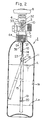
- a container 1 for containing carbon dioxide liquefied under high pressure comprises a seamless container of known type formed vertically long.
- the container 1 having a mouth block at the top thereof is provided with a vertical through hole 2 at the mouth block.
- the inner periphery of the hole 2 is threaded so as to screw a high pressure valve 4 combined with a level gauge tightly therein.
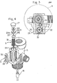
- the body 5 of the valve 4 is made of non-magnetic materials such as brass, having a gas passage 6 for taking out carbon dioxide gas, and a valve member 7 to shut off the passage 6, as shown in fig. 1.
- the valve 4 is arranged to allow out gas from inside of the container 1 through the passage 6 opened by moving the valve member 7 with a handle 8.
- the level gauge 3 for indicating the amount of carbon dioxide contained in the container 1 is assembled in the body 5 at the lateral side of the valve member 7.
- the level gauge 3 comprises an indicator 10 having an indicating member 9 which indicates the amount of liquefied carbon dioxide in the container by the vertical position thereof, and a means for operation 11 which drives the indicating member 9 up and down.
- the means for operation 11 involves a vertical blind hole 12 drilled in the body 5 near to the indicator 10 from the bottom 5a to the upper part near the top of the body 5, a rod 13 having an upper and a lower part, which upper part is inserted in the hole 12 freely slidable up and down in the hole 12, the lower part extending in to the container and a detecting member 16 made of a magnet and fixed on the upper end of the rod 13.
- the rod 13 is biased by a spring 14 upwardly.
- a rigid cylindrical float 15 formed long vertically is suspended in the container 1 under the rod 13.
- the rigid float 15 is articulated to the lower end of the rod 13 at the upper end thereof by an articulating or flexible part 18 con- sistin g of a ring 17.
- the float 15 due to the articulating or flexible part 18 between the rod 13 and the float 15, when the container 1 is tilted or laid down, the float 15 is articulated or bent restorably at the jointed end, that is, at the articulating or flexible part 18, so that the weight of the float 15 I acting on the rod 13 is decreased and permanent bending or damage of the rod 13 eliminated. And as soon as the container 1 is stood up vertically again, the float 15 is vertically aligned with the rod by the gravitation, and the rod 13 will be accurately actuated.
- the float 15 is advantageously provided with a balancing weight 19 at the lower end, or thereabouts, of the float 15.
- a cushion 20 made of rubber is adapted to wrap the lower part of the outer periphery of the balancing weight 19, so as to prevent sounding of the container 1 by collision, and damage of the inner periphery of the container 1 and the float 15.
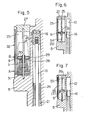
- the upper end of the spring 14 suspending the float 15 is fixed to the metal fitting 21 which is screwed in the hole 12 at the bottom 5 a of the body 5, and through which the rod 13 penetrates slidably up and down.
- the lower end of the spring 14 is fixed to an adjustable fixing member 23 which vertically adjusts by a screw 22 threaded at the lower part of the rod 13.
- a sleeve 24 is inserted to define the lowest position of the detecting member 16.
- the sleeve 24 and the metal fitting 21 may be made in one piece.
- the indicator 10 as shown in fig. 4, comprises an indicating member 9, a hole 25 for housing the member 9 movable up and down therein, drilled down from the top surface of the body 5 and parallel with the vertical blind hole 12, a guide pin 26, around which the indicating member 9 is fitted slidably up and down, stood in the hole 25, and a cap 27 which fixes the top of the pin 26 to the body 5 by its fitting with the body at the opening of the hole 25.
- the indicating member 9 is adapted to move up and down following the detecting member 16 fixed on the upper end of the rod 13.
- the indicating member 9 is provided with a slider 28 fitted around the guide pin 26 for making it easy to slide up and down along the pin 26, an annular magnet 29, and a metal seat 30, both fixed to the slider 28.
- Preventive means S for preventing the indicating member 9 from the misactuation is inserted between the lower surface of this indicating member 9 and the bottom of the hole 25, biasing the indicating member 9 upward.
- the preventive means S is made of soft compressive spring 31 whose shape at free state is shown by a imaginary line in fig. 5.
- the biasing power of the spring 31 is balanced with the weight of the indicating member 9 to elevate it upto a position B higher than the "empty" position A, marked at the lower part of a scale 33 covering an indicating window 32 of the indicator 10, when the indicating member 9 is put on the free spring 31, as in fig. 5.
- the indicating member 9 When a shock is given to the container 1 or the valve 4 at any occasion such as filling or transportation, the indicating member 9 may be droped down toward the "empty" position A where the magnetic attraction between the magnet 29 of the indicating member 9 and the detecting member 16 is effective to adjust the position of the former to the correct position corresponding to any position of the latter.
- the indicating member 9 dropping toward the "empty" position A is received on the preventive means S comprised of the spring 31 at the higher position B and driven to the position corresponding to the detecting member 16 by the magnetic attraction therebetween, before it is droped to the "empty" position A.
- the indicating member 9 is able to move to the correct position and to indicate the amount of carbon dioxide left in the container 1 at any time.
- the indicating member 9 drops down to the "empty" position A, out of the range and, by gravity. However, as soon as the indicating member 9 drops to the "empty" position A, it is elevated by the function of the spring 31 to the following range & without staying at the "empty" position A, so that the indicating member 9 is always able to recover its correct position, following the detecting member 16 instantly.
- the indication of the amount of carbon dioxide left is accurate at any time.
- a modified preventive means S according to the present invention comprises a spiral groove 34 formed at the periphery of the guide pin 26, so as to produce proper resistance against the motion of the indicating member 9 between the pin 26 and the hole 35 of the indicating member 9, through which the pin 26 is fitted slidable.
- the indicating member 9 may be adapted to be removable, together with other parts surrounding it, from the indicator 10 from the imaginary line C in fig. 1.
- preventive means may be modified to comprise a weak spring (not shown) suspended under the cap 27 to pull up the indicatingmember 9.
- a vertical filling pipe 38 having a lower end closed and a filling port 39 near to the lower end is inserted in the container 1 and communicated with the gas passage 6 at the upper end thereof for passage of carbon dioxide gas.
- the filling port 39 faces the side wall 1a of the container opposite the means for operation 11, so as to prevent the rod 13 of the means for operation 11 from bending or being damaged by the spout of liquified carbon dioxide from the filling port 39.
- the magnet 29 of the indicating member 9 attracted to the detecting member 16 by the magnetic attraction thereof is moved up, and the indication line 37, elevated high in the indication window 32, presents that the level in the container 1 is high.
- the float 15 "catches" not only the floating power produced by the liquid phase of the carbon dioxide in the container, but also the floating power produced by the gaseous phase therein which is generated when the temperature is higher than the critical point of carbon dioxide. Therefore, it is possible to accurately detect the total amount left in the container 1 at any desired time, for example, during feeding or at valve operation
- One of the detecting member 16 and the magnet 29 of the indicating member 9 may be substituted by magnetic materials such as iron or steel, instead of magnet.
- the articulating or flexible part 18 according to the invention may be modified variously, as shown in figs. 8 to 17, for example.
- the modified articulating or flexible part 18 shown in fig. 8 comprises a universal joint 42 with a cross member inserted on the rod 13.
- the modified articulating or flexible part 18 shown in fig. 10 comprises double springs 52 and 53, both of which may contribute to suspend the float 15 as well as the spring 14 shown in figs. 1 and 2.
- the modified articulating or flexible part 18 shown in fig. 11, comprises a spring 44 which connects upper and lower parts of the float 15.
- the float 15 is divided into these two parts near the top.
- the contacting surfaces 15a of these pieces are formed in partial spherical surfaces.
- the contacting surface 15a of these pieces 15b are formed in partial spherical surfaces.
- the spring 45 may be substituted with a cylindrical net in the embodiment previously described.
- the floating column 15 is divided into a plurality of pieces 15b along its length, and the pieces 15b are articulated with knuckle joints 18, each of which comprises a spherical extrusion 46 projected from one end 15 a of each piece 15b and a socket hole 47 concaved in each piece 15b at the other end 15a.
- the float 15 is divided into two pieces 15b at a position near the top, and the pieces 15b are jointed by a flexible wire 48 which corresponds to the joint 18.
- the contacting surfaces 15a of the pieces 15b are formed in partial spherical surfaces. In these embodiments, each contacting surface 15a may be formed on a disket 49 made separate from the pieces 15b, as shown in fig. 14.
Landscapes
- Physics & Mathematics (AREA)
- Fluid Mechanics (AREA)
- General Physics & Mathematics (AREA)
- Engineering & Computer Science (AREA)
- Mechanical Engineering (AREA)
- General Engineering & Computer Science (AREA)
- Filling Or Discharging Of Gas Storage Vessels (AREA)
- Measurement Of Levels Of Liquids Or Fluent Solid Materials (AREA)
Applications Claiming Priority (2)
| Application Number | Priority Date | Filing Date | Title |
|---|---|---|---|
| JP1984102782U JPS6124600U (ja) | 1984-07-06 | 1984-07-06 | 残量表示装置付き高圧ガス容器用バルブ |
| JP102782/84U | 1984-07-06 |
Publications (3)
| Publication Number | Publication Date |
|---|---|
| EP0167409A2 true EP0167409A2 (de) | 1986-01-08 |
| EP0167409A3 EP0167409A3 (en) | 1986-12-17 |
| EP0167409B1 EP0167409B1 (de) | 1990-05-09 |
Family
ID=14336708
Family Applications (1)
| Application Number | Title | Priority Date | Filing Date |
|---|---|---|---|
| EP85304820A Expired EP0167409B1 (de) | 1984-07-06 | 1985-07-05 | Niveaumessgerät für einen Flüssigkeitsbehälter |
Country Status (5)
| Country | Link |
|---|---|
| US (1) | US4580450A (de) |
| EP (1) | EP0167409B1 (de) |
| JP (1) | JPS6124600U (de) |
| AU (1) | AU551848B2 (de) |
| DE (1) | DE3577599D1 (de) |
Cited By (4)
| Publication number | Priority date | Publication date | Assignee | Title |
|---|---|---|---|---|
| WO1994007083A1 (en) * | 1992-09-16 | 1994-03-31 | Tokai Corporation | Disposable liquefied gas cylinder with remaining volume alarm and manufacturing method thereof |
| EP0709656A2 (de) | 1994-10-31 | 1996-05-01 | Luxembourg Patent Company S.A. | Hahn mit integriertem Niveaumesser |
| WO2010084518A1 (en) * | 2009-01-26 | 2010-07-29 | Cavagna Group S.P.A. | A valve unit for pressure vessels |
| CN113090938A (zh) * | 2021-03-25 | 2021-07-09 | 中南大学湘雅医院 | 医用液氮储存装置 |
Families Citing this family (20)
| Publication number | Priority date | Publication date | Assignee | Title |
|---|---|---|---|---|
| JPH0633875B2 (ja) * | 1986-10-14 | 1994-05-02 | 株式会社ネリキ | 携帯式酸素吸入ボンベ用残圧表示器付容器弁 |
| US5479820A (en) * | 1993-10-12 | 1996-01-02 | Rochester Gauges, Inc. | Cryogenic gauge |
| US6497145B1 (en) | 1999-06-17 | 2002-12-24 | Rochester Gauges, Inc. | Float gauge with fixed liquid level gauge |
| LU90629B1 (de) | 2000-08-10 | 2006-02-21 | Luxembourg Patent Co | Vorrichtung zum Feststellen eines Gasverlustes auseinem Kohlendioxid-Druckbeh{lter. |
| US7921873B2 (en) | 2004-01-22 | 2011-04-12 | Rochester Gauges, Inc. | Service valve assembly having a stop-fill device and a liquid level indicating dial |
| US7726334B2 (en) | 2004-01-22 | 2010-06-01 | Rochester Gauges, Inc. | Service valve assembly having a stop-fill device and remote liquid level indicator |
| US7293578B2 (en) | 2004-01-22 | 2007-11-13 | Rochester Gauges, Inc. | Gauge assembly having a stop fill device |
| US7219686B2 (en) * | 2005-02-02 | 2007-05-22 | Torrent Trading Ltd. | Tap assembly for a liquid vessel having an overfill protection device and a float controlled magnetic level gauge |
| ITPD20060079A1 (it) | 2006-03-07 | 2007-09-08 | Cavagna Group Spa | Indicatore di livello per recipienti, particolarmente recipienti destinati a contenere gas liquefatti |
| USD583693S1 (en) | 2006-03-30 | 2008-12-30 | Rochester Gauges, Inc. | Dial assembly for a gauge |
| WO2008022340A2 (en) * | 2006-08-18 | 2008-02-21 | Rochester Gauges, Inc. | Service valve assembly having stop-fill device and remote liquid level indicator |
| US7690323B2 (en) * | 2007-10-31 | 2010-04-06 | Rochester Gauges, Inc. | Gauge head assembly with non-magnetic insert |
| CN102667304B (zh) * | 2009-12-21 | 2014-12-10 | 威卡亚历山大威甘德欧洲股份两合公司 | 具有测量连接的气罐 |
| US8833158B2 (en) | 2011-03-16 | 2014-09-16 | Arthur W. Lauder | Sealing system and level monitor for a tank |
| ITMI20122103A1 (it) * | 2012-12-10 | 2014-06-11 | Rivoira S P A | Bombola per gas compressi e liquefatti equipaggiata con un sistema di rilevazione, indicazione e trasmissione del livello della riserva di liquido |
| USD736561S1 (en) * | 2013-06-24 | 2015-08-18 | Isi Gmbh | Capsule |
| JP6793076B2 (ja) * | 2017-03-22 | 2020-12-02 | 未来工業株式会社 | 漏水試験装置 |
| US20190242527A1 (en) * | 2018-02-08 | 2019-08-08 | David Milner | Method and device for withdrawing vapor and measuring liquid level in a cylinder containing liquefied gas |
| CN110715064B (zh) * | 2019-10-31 | 2022-04-15 | 宁波华成阀门有限公司 | 一种区间显示液位计、其显示方法及包含它的气瓶阀 |
| CN110735968A (zh) * | 2019-10-31 | 2020-01-31 | 宁波华成阀门有限公司 | 带液位计的气瓶阀 |
Family Cites Families (9)
| Publication number | Priority date | Publication date | Assignee | Title |
|---|---|---|---|---|
| US1143344A (en) * | 1912-04-01 | 1915-06-15 | Yarnall Waring Co | Automatic meter control. |
| US2029405A (en) * | 1933-05-20 | 1936-02-04 | Karl B Segall | Float control |
| US2634608A (en) * | 1947-10-24 | 1953-04-14 | A P Sorber | Liquid level gauge |
| US2802362A (en) * | 1954-07-26 | 1957-08-13 | Newton E Lyon | Fluid level indicators |
| LU34165A1 (de) * | 1955-02-14 | |||
| DE1241135B (de) * | 1964-12-23 | 1967-05-24 | Hans Siebert Dipl Ing | Einrichtung zur Fuellstandsanzeige bei Fluessiggasflaschen |
| NL7012801A (de) * | 1970-05-02 | 1971-11-04 | ||
| DE2615256A1 (de) * | 1976-04-08 | 1977-10-27 | Vdo Schindling | Einrichtung zum anzeigen eines fluessigkeitsstandes in einem behaelter |
| DE3339357A1 (de) * | 1983-10-29 | 1985-05-09 | Heinrich 6931 Zwingenberg Kübler | Schwimmergesteuerte niveaugrenzwertschaltvorrichtung |
-
1984
- 1984-07-06 JP JP1984102782U patent/JPS6124600U/ja active Granted
-
1985
- 1985-05-17 US US06/735,094 patent/US4580450A/en not_active Expired - Lifetime
- 1985-07-05 DE DE8585304820T patent/DE3577599D1/de not_active Expired - Fee Related
- 1985-07-05 AU AU44625/85A patent/AU551848B2/en not_active Ceased
- 1985-07-05 EP EP85304820A patent/EP0167409B1/de not_active Expired
Cited By (5)
| Publication number | Priority date | Publication date | Assignee | Title |
|---|---|---|---|---|
| WO1994007083A1 (en) * | 1992-09-16 | 1994-03-31 | Tokai Corporation | Disposable liquefied gas cylinder with remaining volume alarm and manufacturing method thereof |
| US5555905A (en) * | 1992-09-16 | 1996-09-17 | Tokai Corporation | Cassette type gas cylinder with remaining volume alarm unit and manufacturing method thereof |
| EP0709656A2 (de) | 1994-10-31 | 1996-05-01 | Luxembourg Patent Company S.A. | Hahn mit integriertem Niveaumesser |
| WO2010084518A1 (en) * | 2009-01-26 | 2010-07-29 | Cavagna Group S.P.A. | A valve unit for pressure vessels |
| CN113090938A (zh) * | 2021-03-25 | 2021-07-09 | 中南大学湘雅医院 | 医用液氮储存装置 |
Also Published As
| Publication number | Publication date |
|---|---|
| US4580450A (en) | 1986-04-08 |
| AU551848B2 (en) | 1986-05-15 |
| JPS6124600U (ja) | 1986-02-13 |
| DE3577599D1 (de) | 1990-06-13 |
| AU4462585A (en) | 1986-01-16 |
| EP0167409B1 (de) | 1990-05-09 |
| JPH0228320Y2 (de) | 1990-07-30 |
| EP0167409A3 (en) | 1986-12-17 |
Similar Documents
| Publication | Publication Date | Title |
|---|---|---|
| EP0167409B1 (de) | Niveaumessgerät für einen Flüssigkeitsbehälter | |
| US6988406B1 (en) | System and method of liquid level detection | |
| US5103674A (en) | Liquid level indicator for high pressure, hostile environment | |
| NO811865L (no) | Fremgangsmaate for lekkasjemaaling. | |
| NZ195201A (en) | Bucket type liquid displacement sensor evaporation compensation | |
| CN1004769B (zh) | 校准压力测量装置的装置 | |
| US4541285A (en) | Method and apparatus for measuring the pressure of a liquid | |
| US4345467A (en) | High temperature pressure transducer system | |
| US3433316A (en) | Weighing device | |
| JPH04507002A (ja) | 漏洩検出装置 | |
| EP1443315A1 (de) | Flüssigkeitsstandanzeiger mit aufblasbarem Schwimmer | |
| EP0886128B1 (de) | Hydrometer für eine kryogene Flüssigkeit | |
| CN221725333U (zh) | 液位检测装置及液位示警系统 | |
| US2678817A (en) | Weighing scale | |
| DK201770512A1 (en) | Instrument for measuring draft difference between both sides of vessel | |
| EP0544784B1 (de) | Vorrichtung mit einem differentiellen schwimmer und sensor, der eine solche enthält | |
| US3979958A (en) | Apparatus for determining interface levels in ground cavities or containers containing liquid or gel-like material | |
| US3616688A (en) | Gradiomanometer apparatus | |
| US3472328A (en) | Weighing device | |
| US4890493A (en) | Automatic tank reading gauge | |
| JP2001208298A (ja) | ガスボンベの残量表示装置 | |
| US1864472A (en) | Measuring instrument or gauge | |
| US2938388A (en) | Liquid-sampling device | |
| US5308272A (en) | Ascent rate indicator | |
| JPH0448399Y2 (de) |
Legal Events
| Date | Code | Title | Description |
|---|---|---|---|
| PUAI | Public reference made under article 153(3) epc to a published international application that has entered the european phase |
Free format text: ORIGINAL CODE: 0009012 |
|
| AK | Designated contracting states |
Designated state(s): DE FR GB SE |
|
| PUAL | Search report despatched |
Free format text: ORIGINAL CODE: 0009013 |
|
| AK | Designated contracting states |
Kind code of ref document: A3 Designated state(s): DE FR GB SE |
|
| 17P | Request for examination filed |
Effective date: 19861222 |
|
| 17Q | First examination report despatched |
Effective date: 19871210 |
|
| GRAA | (expected) grant |
Free format text: ORIGINAL CODE: 0009210 |
|
| AK | Designated contracting states |
Kind code of ref document: B1 Designated state(s): DE FR GB SE |
|
| REF | Corresponds to: |
Ref document number: 3577599 Country of ref document: DE Date of ref document: 19900613 |
|
| ET | Fr: translation filed | ||
| PLBE | No opposition filed within time limit |
Free format text: ORIGINAL CODE: 0009261 |
|
| STAA | Information on the status of an ep patent application or granted ep patent |
Free format text: STATUS: NO OPPOSITION FILED WITHIN TIME LIMIT |
|
| 26N | No opposition filed | ||
| EAL | Se: european patent in force in sweden |
Ref document number: 85304820.5 |
|
| PGFP | Annual fee paid to national office [announced via postgrant information from national office to epo] |
Ref country code: FR Payment date: 20010628 Year of fee payment: 17 |
|
| PGFP | Annual fee paid to national office [announced via postgrant information from national office to epo] |
Ref country code: GB Payment date: 20010629 Year of fee payment: 17 |
|
| PGFP | Annual fee paid to national office [announced via postgrant information from national office to epo] |
Ref country code: SE Payment date: 20010709 Year of fee payment: 17 |
|
| PGFP | Annual fee paid to national office [announced via postgrant information from national office to epo] |
Ref country code: DE Payment date: 20010831 Year of fee payment: 17 |
|
| REG | Reference to a national code |
Ref country code: GB Ref legal event code: IF02 |
|
| PG25 | Lapsed in a contracting state [announced via postgrant information from national office to epo] |
Ref country code: GB Free format text: LAPSE BECAUSE OF NON-PAYMENT OF DUE FEES Effective date: 20020705 |
|
| PG25 | Lapsed in a contracting state [announced via postgrant information from national office to epo] |
Ref country code: SE Free format text: LAPSE BECAUSE OF NON-PAYMENT OF DUE FEES Effective date: 20020706 |
|
| PG25 | Lapsed in a contracting state [announced via postgrant information from national office to epo] |
Ref country code: DE Free format text: LAPSE BECAUSE OF NON-PAYMENT OF DUE FEES Effective date: 20030201 |
|
| GBPC | Gb: european patent ceased through non-payment of renewal fee |
Effective date: 20020705 |
|
| EUG | Se: european patent has lapsed | ||
| PG25 | Lapsed in a contracting state [announced via postgrant information from national office to epo] |
Ref country code: FR Free format text: LAPSE BECAUSE OF NON-PAYMENT OF DUE FEES Effective date: 20030331 |
|
| REG | Reference to a national code |
Ref country code: FR Ref legal event code: ST |