EP0167504A2 - Fräser - Google Patents
Fräser Download PDFInfo
- Publication number
- EP0167504A2 EP0167504A2 EP85850177A EP85850177A EP0167504A2 EP 0167504 A2 EP0167504 A2 EP 0167504A2 EP 85850177 A EP85850177 A EP 85850177A EP 85850177 A EP85850177 A EP 85850177A EP 0167504 A2 EP0167504 A2 EP 0167504A2
- Authority
- EP
- European Patent Office
- Prior art keywords
- shoe
- supporting surface
- adjustment means
- cutter body
- wedge face
- Prior art date
- Legal status (The legal status is an assumption and is not a legal conclusion. Google has not performed a legal analysis and makes no representation as to the accuracy of the status listed.)
- Granted
Links
Images


Classifications
-
- B—PERFORMING OPERATIONS; TRANSPORTING
- B23—MACHINE TOOLS; METAL-WORKING NOT OTHERWISE PROVIDED FOR
- B23C—MILLING
- B23C5/00—Milling-cutters
- B23C5/16—Milling-cutters characterised by physical features other than shape
- B23C5/20—Milling-cutters characterised by physical features other than shape with removable cutter bits or teeth or cutting inserts
- B23C5/22—Securing arrangements for bits or teeth or cutting inserts
- B23C5/24—Securing arrangements for bits or teeth or cutting inserts adjustable
- B23C5/2462—Securing arrangements for bits or teeth or cutting inserts adjustable the adjusting means being oblique surfaces
-
- B—PERFORMING OPERATIONS; TRANSPORTING
- B23—MACHINE TOOLS; METAL-WORKING NOT OTHERWISE PROVIDED FOR
- B23C—MILLING
- B23C5/00—Milling-cutters
- B23C5/16—Milling-cutters characterised by physical features other than shape
- B23C5/20—Milling-cutters characterised by physical features other than shape with removable cutter bits or teeth or cutting inserts
- B23C5/22—Securing arrangements for bits or teeth or cutting inserts
- B23C5/2204—Securing arrangements for bits or teeth or cutting inserts with cutting inserts clamped against the walls of the recess in the cutter body by a clamping member acting upon the wall of a hole in the insert
- B23C5/2226—Securing arrangements for bits or teeth or cutting inserts with cutting inserts clamped against the walls of the recess in the cutter body by a clamping member acting upon the wall of a hole in the insert for plate-like cutting inserts fitted on an intermediate carrier, e.g. shank fixed in the cutter body
-
- Y—GENERAL TAGGING OF NEW TECHNOLOGICAL DEVELOPMENTS; GENERAL TAGGING OF CROSS-SECTIONAL TECHNOLOGIES SPANNING OVER SEVERAL SECTIONS OF THE IPC; TECHNICAL SUBJECTS COVERED BY FORMER USPC CROSS-REFERENCE ART COLLECTIONS [XRACs] AND DIGESTS
- Y10—TECHNICAL SUBJECTS COVERED BY FORMER USPC
- Y10T—TECHNICAL SUBJECTS COVERED BY FORMER US CLASSIFICATION
- Y10T407/00—Cutters, for shaping
- Y10T407/19—Rotary cutting tool
- Y10T407/1906—Rotary cutting tool including holder [i.e., head] having seat for inserted tool
- Y10T407/1908—Face or end mill
- Y10T407/1912—Tool adjustable relative to holder
- Y10T407/1914—Radially
- Y10T407/1916—And axially
-
- Y—GENERAL TAGGING OF NEW TECHNOLOGICAL DEVELOPMENTS; GENERAL TAGGING OF CROSS-SECTIONAL TECHNOLOGIES SPANNING OVER SEVERAL SECTIONS OF THE IPC; TECHNICAL SUBJECTS COVERED BY FORMER USPC CROSS-REFERENCE ART COLLECTIONS [XRACs] AND DIGESTS
- Y10—TECHNICAL SUBJECTS COVERED BY FORMER USPC
- Y10T—TECHNICAL SUBJECTS COVERED BY FORMER US CLASSIFICATION
- Y10T407/00—Cutters, for shaping
- Y10T407/19—Rotary cutting tool
- Y10T407/1906—Rotary cutting tool including holder [i.e., head] having seat for inserted tool
- Y10T407/1908—Face or end mill
- Y10T407/192—Face or end mill with separate means to fasten tool to holder
- Y10T407/1922—Wedge clamp element
-
- Y—GENERAL TAGGING OF NEW TECHNOLOGICAL DEVELOPMENTS; GENERAL TAGGING OF CROSS-SECTIONAL TECHNOLOGIES SPANNING OVER SEVERAL SECTIONS OF THE IPC; TECHNICAL SUBJECTS COVERED BY FORMER USPC CROSS-REFERENCE ART COLLECTIONS [XRACs] AND DIGESTS
- Y10—TECHNICAL SUBJECTS COVERED BY FORMER USPC
- Y10T—TECHNICAL SUBJECTS COVERED BY FORMER US CLASSIFICATION
- Y10T407/00—Cutters, for shaping
- Y10T407/19—Rotary cutting tool
- Y10T407/1906—Rotary cutting tool including holder [i.e., head] having seat for inserted tool
- Y10T407/1934—Rotary cutting tool including holder [i.e., head] having seat for inserted tool with separate means to fasten tool to holder
- Y10T407/1938—Wedge clamp element
Definitions
- the present invention relates to a milling cutter comprising a cutter body, at least one shoe carrying a cutting insert and adjustably secured to the cutter body, and adjustment means for adjusting the position of the shoe in the cutter body to vary the extent of projection of the cutting insert from the cutter body.
- the adjustment means is provided with a supporting surface intended to rest against a corresponding supporting surface on the cutter body and a wedge face intended to rest against a corresponding wedge face on the shoe.
- the milling cutter further comprises clamping means adapted to clamp the shoe in adjusted position.
- Milling cutters of this prior art typ are disclosed in for instance US-A-3847555, DE-A-2339873 and DE-B-2806079.
- One object of the present invention is therefore to provide a milling cutter in which the shoe cannot be displaced out of its accurately adjusted position when being clamped by means of the clamping means.
- Another object of the invention is to provide a milling cutter in which the shoes, when seen in the circumferential direction, can be mounted as close to each other as possible.
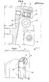
- Fig. 1 shows an end view of one embodiment of a milling cutter according to the invention.
- the milling cutter shown in the drawings comprises a cutter body 10 and a plurality of cutting inserts 11. Each of the cutting inserts is mounted in a shoe or cassette 12.
- the position of the shoes 12 in the cutter body 10 can be adjusted by means of an adjustment means 13.
- an adjustment means 13 By adjusting the position of the shoes 12 the extent of projection of the cutting insert 11 from the cutter body 10 can be varied.
- a clamping means comprising a fastening screw 14 and a clamping screw 16 cooperating with a pin 15.
- the screws 14,16 and the pin 15 are described in detail in the following.
- the adjustment means 13 is provided with a supporting surface 17 which is adapted to rest against a corresponding supporting surface 18 on the cutter body 10.
- the adjustment means 13 is also provided with a wedge face 19 which is adapted to rest against a corresponding wedge face 20 on the shoe 12.
- the adjustment means 13 When the position of the shoe 12 in the cutter body 10 is adjusted the adjustment means 13 is displaced in its longitudinal direction by means of a screw 21 screwed into the cutter body. When the adjustment 13 is displaced, thus, a relative movement does arise along the wedge faces 19,20.
- the supporting surface 17 of the adjustment means 13 and the supporting surface 18 on the cutter body 10 are in a manner known per se generally curved. Usually the supporting surfaces 17,18 are partially cylindrical as in the illustrated embodiment. However, other shapes might be used, for instance a generally curved one having faceted surface portions, provided that they allow the adjustment means 13 to be at least somewhat rotated about its longitudinal axis.
- the fastening screw 14 has such a direction that, upon clamping of the shoe 12 by means of the fastening screw, force components do arise acting on the wedge face 19 of the adjustment means 13, a longitudinal supporting surface 22 on the cutter body 10 and a generally transversely thereto extending supporting surface 23 on the cutter body 10. If a conventional adjustment menas is used, wherein the sector of a circle generally formed by the partially cylindrical supporting surface has an included angle equal to 180°, there is a risk that the adjustment means during adjustment of the shoe might have been rotated somewhat out of the position in which exact abutment does exist between the whole wedge faces 19,20. When the fastening screw 14 is tightened, then, the adjustment means will be caused to rotate back to this position, thereby moving the shoe out of its exactly adjusted position.
- the adjustment means 13 is provided with a tongued portion 24 which has a supporting or localizing surface 25 for the shoe 12.
- the supporting surface 25, which is a continuation of the supporting surface 22, ensures that correct mutual position is obtained between the adjustment means 13 and the shoe 12. Due to the tongued portion 24, thus, the sector of a circle formed by the partially cylindrical supporting surface 17 has an included angle ol larger than 180 0 .
- the adjustment means 13, thus, is adapted to bridge an inner corner 26 on the shoe 12.
- the supporting surfaces 17,18 are circular-cylindrical. As said above, however, other shapes, for instance faceted ones, might be used which allow turning of the adjustment means 13.
- the supporting surface 25 on the adjustment means 13 extends generally transversely relative to the wedge face 19.
- the wedge face 19 and the supporting surface 25 therebetween form an included angle ⁇ smaller than 90°.
- the wedge face 19 of the adjustment means 13 has such a direction that the shoe 12 is displaced axially outwards, i.e. downwards in Fig. 3, when the adjustment means 13 is displaced radially inwards, i.e. to the left in Fig. 3.
- the present invention also seeks to make possible mounting of the shoes 12 as close to each other as possible when seen in the circumferential direction of the milling cutter.
- the cutting inserts 11 are secured to the shoes 12 by means of screws 27, which means that spacious wedges are not required.
- the clamping means of the shoe therefore comprises a pin 15 which is displaceably arranged in a bore in the shoe at the outer end thereof.
- the pin 15 can be forced against a supporting surface 28 on the cutter body opposed to the supporting surface 22 by means of a clamping screw 16 which is screwed into the shoe 12 and movable generally seen in the longitudinal direction of the shoe.
- the clamping screw 16, thus being movable generally perpendicular to the longitudinal direction of the pin 15, is provided with a conical portion 29 which is adapted to rest against the end face of the pin 15 opposed to the supporting surface 28.
Landscapes
- Engineering & Computer Science (AREA)
- Mechanical Engineering (AREA)
- Milling Processes (AREA)
- Transition And Organic Metals Composition Catalysts For Addition Polymerization (AREA)
- Lubrication Of Internal Combustion Engines (AREA)
- Ultra Sonic Daignosis Equipment (AREA)
- Turning (AREA)
- Shovels (AREA)
Priority Applications (1)
| Application Number | Priority Date | Filing Date | Title |
|---|---|---|---|
| AT85850177T ATE50525T1 (de) | 1984-07-05 | 1985-05-17 | Fraeser. |
Applications Claiming Priority (2)
| Application Number | Priority Date | Filing Date | Title |
|---|---|---|---|
| SE8403567 | 1984-07-05 | ||
| SE8403567A SE454490B (sv) | 1984-07-05 | 1984-07-05 | Fres med instellbar kassett |
Publications (3)
| Publication Number | Publication Date |
|---|---|
| EP0167504A2 true EP0167504A2 (de) | 1986-01-08 |
| EP0167504A3 EP0167504A3 (en) | 1987-06-16 |
| EP0167504B1 EP0167504B1 (de) | 1990-02-28 |
Family
ID=20356450
Family Applications (1)
| Application Number | Title | Priority Date | Filing Date |
|---|---|---|---|
| EP85850177A Expired - Lifetime EP0167504B1 (de) | 1984-07-05 | 1985-05-17 | Fräser |
Country Status (6)
| Country | Link |
|---|---|
| US (1) | US4623284A (de) |
| EP (1) | EP0167504B1 (de) |
| JP (2) | JPH0639004B2 (de) |
| AT (1) | ATE50525T1 (de) |
| DE (1) | DE3576132D1 (de) |
| SE (1) | SE454490B (de) |
Cited By (5)
| Publication number | Priority date | Publication date | Assignee | Title |
|---|---|---|---|---|
| EP0182290A3 (de) * | 1984-11-15 | 1988-04-20 | Walter Kieninger GmbH Hartmetall- und Diamantwerkzeugfabrik | Messerkopf |
| EP0431746A1 (de) * | 1989-11-09 | 1991-06-12 | Sandvik Limited | Fräswerkzeuge |
| EP0499280A1 (de) * | 1991-02-14 | 1992-08-19 | Mitsubishi Materials Corporation | Fräswerkzeug mit Schneideinsatz |
| GB2332161A (en) * | 1997-12-13 | 1999-06-16 | C And D Technologies Limited | Reuse of disposable cutter inserts |
| CN104768687A (zh) * | 2012-09-18 | 2015-07-08 | 硬质金属工具厂保罗霍恩有限公司 | 用于工件切削加工的切削嵌件和工具 |
Families Citing this family (14)
| Publication number | Priority date | Publication date | Assignee | Title |
|---|---|---|---|---|
| DE3708034A1 (de) * | 1987-03-12 | 1988-09-22 | Zerspanungstech Gmbh & Co Kg | Messerkopf |
| DE3922963C2 (de) * | 1989-07-12 | 1994-06-01 | Widia Heinlein Gmbh | Drehräumwerkzeug |
| ATE240179T1 (de) * | 1996-03-19 | 2003-05-15 | Iscar Ltd | Schneidwerkzeuganordnung |
| DE10012818B4 (de) * | 2000-03-16 | 2006-04-06 | Wilhelm Fette Gmbh | Plan- oder Eckfräser |
| DE10234030A1 (de) * | 2002-07-26 | 2004-02-05 | Widia Gmbh | Schneidwerkzeug für die spanabhebende Bearbeitung |
| BR0313730A (pt) * | 2002-08-13 | 2005-07-12 | Kennametal Widia Gmbh & Co Kg | Ferramenta em forma de disco ou de régua |
| US8327742B1 (en) * | 2008-03-07 | 2012-12-11 | Lockheed Martin Corporation | Diamond tool micro-height-adjuster within a multi-tool rotating head |
| US9216461B2 (en) * | 2011-07-19 | 2015-12-22 | Iscar, Ltd. | Cutting body configured for fine-tuning and metal-working machine tool comprising a plurality thereof |
| US9862040B2 (en) * | 2014-09-30 | 2018-01-09 | Sandvik Intellectual Property Ab | Mechanism for enhanced, bi-directional fine adjustment of cutting insert cartridges in machine tools |
| US20170151614A1 (en) * | 2015-06-19 | 2017-06-01 | EIP Holdings, LLC | Adjustable face mill and method of manufacture |
| CN105328224B (zh) * | 2015-11-17 | 2017-12-26 | 株洲钻石切削刀具股份有限公司 | 旋转加工刀具 |
| CN105328252A (zh) * | 2015-11-17 | 2016-02-17 | 株洲钻石切削刀具股份有限公司 | 一种旋转加工刀具 |
| US10144071B2 (en) | 2017-03-16 | 2018-12-04 | Iscar, Ltd. | Tool holder having position adjustment arrangement and cutting tool |
| DE102019205717A1 (de) * | 2019-04-18 | 2020-10-22 | Gühring KG | Zerspanungswerkzeug mit einstellbar fixiertem schneideinsatz |
Family Cites Families (13)
| Publication number | Priority date | Publication date | Assignee | Title |
|---|---|---|---|---|
| DD39460A (de) * | ||||
| FR997478A (fr) * | 1949-09-14 | 1952-01-07 | Perfectionnement apportés dans l'établissement des fraises à outils multiples | |
| DE1632662U (de) * | 1951-07-30 | 1951-12-27 | Hermann Greiner K G | Spannorgan zum halten der messer in fraeser-messerkoepfen. |
| DE1175963B (de) * | 1958-10-25 | 1964-08-13 | Biax Werkzeuge G M B H Praez S | Praezisionsmesserkopf mit einstellbaren Schneiden |
| GB1063441A (en) * | 1964-03-02 | 1967-03-30 | Wickman Wimet Ltd | Cutting tools |
| US3270396A (en) * | 1965-02-25 | 1966-09-06 | O K Tool Co Inc | Bit holder |
| JPS4332059Y1 (de) * | 1966-04-28 | 1968-12-26 | ||
| GB1392445A (en) * | 1971-06-03 | 1975-04-30 | Lloyd Ltd Richard | Milling cutter |
| JPS5249593B2 (de) * | 1972-08-08 | 1977-12-17 | ||
| JPS4978991A (de) * | 1972-11-16 | 1974-07-30 | ||
| DE2806079C2 (de) * | 1978-02-14 | 1979-10-31 | Guenther 8500 Nuernberg Hertel | Fräswerkzeug mit einstellbar angeordneten Schneideinsätzen |
| US4311418A (en) * | 1980-06-24 | 1982-01-19 | General Electric Company | Adjustable axial and radial locating wedge assemblies for an indexable insert cutting tool |
| JP5835807B2 (ja) | 2012-07-04 | 2015-12-24 | 日本電信電話株式会社 | 光デバイスの周波数測定装置 |
-
1984
- 1984-07-05 SE SE8403567A patent/SE454490B/sv not_active IP Right Cessation
-
1985
- 1985-05-17 AT AT85850177T patent/ATE50525T1/de not_active IP Right Cessation
- 1985-05-17 EP EP85850177A patent/EP0167504B1/de not_active Expired - Lifetime
- 1985-05-17 DE DE8585850177T patent/DE3576132D1/de not_active Expired - Lifetime
- 1985-06-27 US US06/749,395 patent/US4623284A/en not_active Expired - Fee Related
- 1985-07-03 JP JP60144860A patent/JPH0639004B2/ja not_active Expired - Lifetime
-
1993
- 1993-06-08 JP JP5137751A patent/JPH0761563B2/ja not_active Expired - Lifetime
Cited By (8)
| Publication number | Priority date | Publication date | Assignee | Title |
|---|---|---|---|---|
| EP0182290A3 (de) * | 1984-11-15 | 1988-04-20 | Walter Kieninger GmbH Hartmetall- und Diamantwerkzeugfabrik | Messerkopf |
| EP0431746A1 (de) * | 1989-11-09 | 1991-06-12 | Sandvik Limited | Fräswerkzeuge |
| US5123786A (en) * | 1989-11-09 | 1992-06-23 | Sandvik Ltd. | Milling cutters |
| EP0499280A1 (de) * | 1991-02-14 | 1992-08-19 | Mitsubishi Materials Corporation | Fräswerkzeug mit Schneideinsatz |
| US5209610A (en) * | 1991-02-14 | 1993-05-11 | Mitsubishi Materials Corporation | Throwaway milling cutter |
| GB2332161A (en) * | 1997-12-13 | 1999-06-16 | C And D Technologies Limited | Reuse of disposable cutter inserts |
| CN104768687A (zh) * | 2012-09-18 | 2015-07-08 | 硬质金属工具厂保罗霍恩有限公司 | 用于工件切削加工的切削嵌件和工具 |
| CN104768687B (zh) * | 2012-09-18 | 2017-08-18 | 硬质金属工具厂保罗霍恩有限公司 | 用于工件切削加工的切削嵌件和工具 |
Also Published As
| Publication number | Publication date |
|---|---|
| JPH0761563B2 (ja) | 1995-07-05 |
| JPH0639619A (ja) | 1994-02-15 |
| SE8403567L (sv) | 1986-01-06 |
| SE454490B (sv) | 1988-05-09 |
| JPH0639004B2 (ja) | 1994-05-25 |
| ATE50525T1 (de) | 1990-03-15 |
| US4623284A (en) | 1986-11-18 |
| SE8403567D0 (sv) | 1984-07-05 |
| EP0167504A3 (en) | 1987-06-16 |
| DE3576132D1 (de) | 1990-04-05 |
| EP0167504B1 (de) | 1990-02-28 |
| JPS6125708A (ja) | 1986-02-04 |
Similar Documents
| Publication | Publication Date | Title |
|---|---|---|
| EP0167504A2 (de) | Fräser | |
| US5688080A (en) | Tool shaft with detachable blade having wedge groove contacting a movable wedge | |
| EP0039539B1 (de) | Schwimmender Spannkeil für einen indexierbaren Schneideinsatz | |
| BRPI0206528B1 (pt) | fresa axial tendo múltiplos insertos de corte e sede de inserto ajustável para os insertos de corte de fresas axiais | |
| US20080003068A1 (en) | Insert-indexable tool | |
| US4353669A (en) | Device for machine reamer | |
| KR20040058303A (ko) | 조정가능한 커팅인써트를 구비한 회전가능한 커팅 툴 | |
| US4211507A (en) | Rotary cutting tool with radially adjustable, reversible tool bits | |
| US4566826A (en) | Adjustable insert support | |
| US4744703A (en) | Rotary cutter for slotting or cut-off | |
| GB2080710A (en) | Reamer with insert blade | |
| KR20010022358A (ko) | 조정 기구 | |
| US4050129A (en) | Milling cutter | |
| US4033018A (en) | Indexable milling cutter | |
| EP0096669B1 (de) | Fräser mit auswechselbaren Schneideinsätzen | |
| EP0257005A1 (de) | Werkzeug zur spanabhebenden Bearbeitung | |
| US4555202A (en) | Tool holder with tool | |
| US5329978A (en) | Planer | |
| JPH0325846Y2 (de) | ||
| US5148609A (en) | Adjusting locator for cutting tools | |
| JPS6144736Y2 (de) | ||
| KR200438118Y1 (ko) | 조정 기구 | |
| SE447881B (sv) | Fres med justerbar skerhallare | |
| JPH0615518A (ja) | 切削工具 | |
| JPH11262811A (ja) | スローアウェイ式正面フライスおよびスローアウェイチップ |
Legal Events
| Date | Code | Title | Description |
|---|---|---|---|
| PUAI | Public reference made under article 153(3) epc to a published international application that has entered the european phase |
Free format text: ORIGINAL CODE: 0009012 |
|
| AK | Designated contracting states |
Designated state(s): AT DE FR GB IT |
|
| 17P | Request for examination filed |
Effective date: 19860603 |
|
| PUAL | Search report despatched |
Free format text: ORIGINAL CODE: 0009013 |
|
| AK | Designated contracting states |
Kind code of ref document: A3 Designated state(s): AT DE FR GB IT |
|
| 17Q | First examination report despatched |
Effective date: 19881028 |
|
| GRAA | (expected) grant |
Free format text: ORIGINAL CODE: 0009210 |
|
| AK | Designated contracting states |
Kind code of ref document: B1 Designated state(s): AT DE FR GB IT |
|
| ITF | It: translation for a ep patent filed | ||
| REF | Corresponds to: |
Ref document number: 50525 Country of ref document: AT Date of ref document: 19900315 Kind code of ref document: T |
|
| REF | Corresponds to: |
Ref document number: 3576132 Country of ref document: DE Date of ref document: 19900405 |
|
| ET | Fr: translation filed | ||
| ITTA | It: last paid annual fee | ||
| PLBE | No opposition filed within time limit |
Free format text: ORIGINAL CODE: 0009261 |
|
| STAA | Information on the status of an ep patent application or granted ep patent |
Free format text: STATUS: NO OPPOSITION FILED WITHIN TIME LIMIT |
|
| 26N | No opposition filed | ||
| PGFP | Annual fee paid to national office [announced via postgrant information from national office to epo] |
Ref country code: GB Payment date: 19930507 Year of fee payment: 9 |
|
| PGFP | Annual fee paid to national office [announced via postgrant information from national office to epo] |
Ref country code: FR Payment date: 19930510 Year of fee payment: 9 |
|
| PGFP | Annual fee paid to national office [announced via postgrant information from national office to epo] |
Ref country code: AT Payment date: 19930512 Year of fee payment: 9 |
|
| PGFP | Annual fee paid to national office [announced via postgrant information from national office to epo] |
Ref country code: DE Payment date: 19930602 Year of fee payment: 9 |
|
| PG25 | Lapsed in a contracting state [announced via postgrant information from national office to epo] |
Ref country code: GB Effective date: 19940517 Ref country code: AT Effective date: 19940517 |
|
| GBPC | Gb: european patent ceased through non-payment of renewal fee |
Effective date: 19940517 |
|
| PG25 | Lapsed in a contracting state [announced via postgrant information from national office to epo] |
Ref country code: FR Effective date: 19950131 |
|
| PG25 | Lapsed in a contracting state [announced via postgrant information from national office to epo] |
Ref country code: DE Effective date: 19950201 |
|
| REG | Reference to a national code |
Ref country code: FR Ref legal event code: ST |