EP0167509B1 - Gewindeverstellvorrichtung - Google Patents
Gewindeverstellvorrichtung Download PDFInfo
- Publication number
- EP0167509B1 EP0167509B1 EP85850218A EP85850218A EP0167509B1 EP 0167509 B1 EP0167509 B1 EP 0167509B1 EP 85850218 A EP85850218 A EP 85850218A EP 85850218 A EP85850218 A EP 85850218A EP 0167509 B1 EP0167509 B1 EP 0167509B1
- Authority
- EP
- European Patent Office
- Prior art keywords
- thread
- bodies
- recess
- nut
- threaded
- Prior art date
- Legal status (The legal status is an assumption and is not a legal conclusion. Google has not performed a legal analysis and makes no representation as to the accuracy of the status listed.)
- Expired - Lifetime
Links
- 238000010276 construction Methods 0.000 description 2
- 238000010521 absorption reaction Methods 0.000 description 1
- 230000006978 adaptation Effects 0.000 description 1
- XAGFODPZIPBFFR-UHFFFAOYSA-N aluminium Chemical compound [Al] XAGFODPZIPBFFR-UHFFFAOYSA-N 0.000 description 1
- 229910052782 aluminium Inorganic materials 0.000 description 1
- 230000006835 compression Effects 0.000 description 1
- 238000007906 compression Methods 0.000 description 1
- 238000004512 die casting Methods 0.000 description 1
- 238000009432 framing Methods 0.000 description 1
- 238000004519 manufacturing process Methods 0.000 description 1
- 230000000717 retained effect Effects 0.000 description 1
- 239000002023 wood Substances 0.000 description 1
Images


Classifications
-
- E—FIXED CONSTRUCTIONS
- E04—BUILDING
- E04H—BUILDINGS OR LIKE STRUCTURES FOR PARTICULAR PURPOSES; SWIMMING OR SPLASH BATHS OR POOLS; MASTS; FENCING; TENTS OR CANOPIES, IN GENERAL
- E04H15/00—Tents or canopies, in general
- E04H15/32—Parts, components, construction details, accessories, interior equipment, specially adapted for tents, e.g. guy-line equipment, skirts, thresholds
- E04H15/56—Floors
-
- B—PERFORMING OPERATIONS; TRANSPORTING
- B66—HOISTING; LIFTING; HAULING
- B66F—HOISTING, LIFTING, HAULING OR PUSHING, NOT OTHERWISE PROVIDED FOR, e.g. DEVICES WHICH APPLY A LIFTING OR PUSHING FORCE DIRECTLY TO THE SURFACE OF A LOAD
- B66F3/00—Devices, e.g. jacks, adapted for uninterrupted lifting of loads
- B66F3/08—Devices, e.g. jacks, adapted for uninterrupted lifting of loads screw operated
Definitions
- This invention concerns a thread joint particularly in connection with adjustable legs or jacks for platforms for instance in the shape of floors in tents used together with caravans in order to increase the available protected area.
- a main problem in establishing a floor supported in many points which is to be adjustable to any surface is that the adjusting possibility preferably shall be great as compared to the thickness of the floor.
- jacks of known type can be used but they have in common, firstly, that they are relatively complicated and, secondly, it is difficult to obtain sufficient adjustment in comparison with the floor thickness or, in other words, it is difficult to obtain a great relationship between the maximum and the minimum length of the jack or the leg. This is in practice particularly the case with floors under tents arranged in connection with caravans.
- the ground under the floor is mostly not prepared for the floor and the floor is necessary to enable the use of the tent in bad weather since the ground might become muddy and slippery.
- This need of a floor under caravan tents has been solved by using used wood in different shapes, for instance from loading pallets.
- the construction is definitely not easy to move.
- the different legs of the floor may sink differently with time, resulting in an uneven surface of the floor and a corresponding time consuming work to regain the even surface.
- An uneven floor is not only aesthetically unpleasant but may be uncomfortable and dangerous.
- FR-A-2 178 736 describing a jack or support leg that is extendable by means of extension pieces that can be inserted between the head of the jack and its adjusting or lifting threaded member.
- the parts are alined to each other by means of holes and pins extending into these holes. In this way the adjustable height is increased but the jack will be very cumbersome to use, since lateral access is necessary.
- a thread joint comprising at least two threaded bodies with identical outer threads, which bodies are provided with interlocking means capable of transfering a turning force between the bodies in at least one direction, and abutment means capable of transfering forces in at least one axial direction between the threaded bodies and that in the abutting and force transfering position the threads of the bodies coincide and form a single continuous thread that can be threaded into and through a nut.
- the tread joint in accordance with the invention makes it possible to continuously lengthen for instance the screw part of a jack that can be inserted from above in the case with the floor until the sufficient length of a leg is obtained.
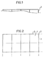
- FIG. 1 shows a lateral projection of a floor in accordance with the invention
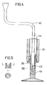
- Fig 2 the same floor as seen from above
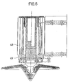
- Fig 3 a support leg of a tent floor in accordance with the invention
- Fig 4 the same support leg as in Fig 3 but with means for the operation
- Fig 5 details of Figs 4, 6 and 7 of alternative embodiments of the support leg as far its locking is concerned
- Figs 8 and 9 a section of a reciprocal locking of the support leg parts
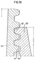
- Fig 10 the thread profile.
- the tent floor according to the invention comprises a plurality of square modules 1 which are connected at their corner points by means of jacks or support legs 2 which will be described in greater detail below.
- the length of the support legs 2 is adjustable, which allows of adaptation to the ground.
- the lateral beams 3 framing the modules are restrictedly elastically attached to the support legs 2 the risk of no ground contact of a support leg, if this is carelessly adjusted with following great breaking risks is eliminated.
- the adjustment of the support legs is also simplified so that the floor becomes even and all the support legs absorb the pressure. If the structure should be non-elastic it would be difficult to decide if the force absorption at each support leg functions.
- By using the above-mentioned support leg it will, moreover, always be easy to adapt the level of the tent floor from the upper side to possible ground changes.
- a support leg in the form of a support leg housing 31 is shown, in the bottom of which a nut 32 is arranged nonrotatably.
- the threaded support leg 33 extends through this nut 32.
- the support leg consists of a lower portion 34 and an upper joint portion 35. Moreover, such a joint portion is shown freely above the very support leg.
- the support leg is terminated at its bottom portion by a foot member 36.
- Each support leg portion 34, 35 encludes a cylindrical, lightly tapered hole into which a corresponding projecting pin 37 on the portions 35 of the support leg portions 35 can be pushed. When the tapered pins 37 are pushed into the tapered holes 38 the shoulder portion 39 between pins and thread will abut against the upper end 40 of the support leg portion located below.
- a key grip is arranged in the bottom of each tapered recess 38 at the very front or down on the pin, respectively, which key grip is quite simply semi-circular in this case.
- this key grip 41 the threads agree for the consecutive support leg portions. In this way it will be possible to fill up with support leg portions 35 as desired when the support leg 33 is threaded downwards until it gets into contact with the ground and has lifted the support leg housing 31 to the desired height.
- the key or the crank 42 shown in Fig 11 is used for screwing down the support leg.
- This crank is also provided with a key grip corresponding to the key grip 41 furthest below.
- crank 42 is further provided with a stop means 44 which will abut the upper end of the support leg housing 31 because there is a need of a new support leg portion when the support leg has been screwed down enough. Therefore the key grip of the crank 42 and the support leg portion 43 will slide apart until the bevelling 43 presses the key 42 upwards.
- the crank is bevelled the driving ability is only lost in one direction while it is maintained in the other direction, and therefore the support leg can always be screwed up again if desired.
- the support leg 33 is slowly turning the nut 32, this has outer conical surfaces with the cone tip upwards in the bottom 45 of the support leg housing 31.
- the nut 32 is held on its place axially by a washer 46 which is held fast in turn by means of nuts 47 which also holds the bottom 45 of the support leg housing 31 to the support leg housing 31.
- a washer 46 which is held fast in turn by means of nuts 47 which also holds the bottom 45 of the support leg housing 31 to the support leg housing 31.
- the nut 32 has a sligth axial play and is for instance provided with a slot or is lightly elastic a compression of the nut 32 against the parts 34 or 35 of the support leg is obtained, as soon as there is a load on the support leg, which prevents thread wandering.
- the support legs can also be locked in the way shown in Fig 6 where the support leg 50 is directly threaded in the bottom 49 of a support leg housing 48.
- a threaded washer 51 is arranged beneath the bottom 49 with a slight axial play, which washer is also threaded onto the support leg 50.
- the axial play of the washer and its turning stop, respectively, are so arranged that the thread in the bottom and the washer 51, respectively, agree at downward turning while at upward threading the washer must in a way not shown be retained in this position (e.g. by pushing down a rod or the like through a hole arranged in the housing) in order to prevent the washer from accompanying the turning of the support leg so much that the threads are wedged reciprocally.
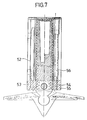
- Fig 7 shows a further way of locking the support leg in a definite position.
- the bottom 53 of the support leg housing 52 is provided with a horizontal slot 54.
- a screw 50 is threaded which can be actuated from above and clamps the slot 54 together and locks the threading in this way.
- a device such as is exemplified in Figs 3, 8 and 9 can be used.
- Two recesses 57 and 58, respectively, are arranged straight in front of each other in the cylindrical upper portion of each support leg section.
- the recess 58 is relatively small while the recess 57 is relatively broad and a circlip 59 is arranged in these.
- the circlip has axially a height corresponding to abut the pitch as apparent from Fig 3.
- the spring ring 59 In unactuated state the spring ring 59 is in the position shown in Fig 9, i.e. it extends to the thread tops.
- the circlip 59 is pressed by the nut inwards in radial direction.
- the circlip will then expand in the portions being within the tapered recess of the support leg portion where, moreover, a recess is arranged to be able to absorb at least the width of the circlip so that it comes on a level with the cone surface at its lower edge.
- the circlip will then enter the position shown in Fig 8. In the position shown in Fig 8 the circlip 59 will release the groove 60 running all around on the support leg portion 35 and this can be removed out of the lower support leg portion.
- support leg portions can always be inserted and taken out of support leg portions located below when the circlip section 53 is in the nut 32.
- the internal groove running all around in the cylindrical portion of the support leg section 35 need not be undercut as the lower edge of the circlip 59 need only be pressed in to the level of the conical surface therein and consequently it is possible to manufacture the support leg pieces by die casting in e.g. aluminum.
- the axial play of the thread in the nut 32 are preferably a little greater than the turning play of the reciprocal key grips. After adjustment of the support leg this is upwardly sealed by a cover.
Landscapes
- Engineering & Computer Science (AREA)
- Structural Engineering (AREA)
- Architecture (AREA)
- Mechanical Engineering (AREA)
- Life Sciences & Earth Sciences (AREA)
- Geology (AREA)
- Civil Engineering (AREA)
- Vehicle Body Suspensions (AREA)
- Tension Adjustment In Filamentary Materials (AREA)
- Optical Couplings Of Light Guides (AREA)
- Mutual Connection Of Rods And Tubes (AREA)
- Tents Or Canopies (AREA)
- Mechanical Treatment Of Semiconductor (AREA)
- Floor Finish (AREA)
Claims (9)
- Gewindeverbindung, umfassend wenigstens zwei mit gewinde versehene Körper (34, 35) mit identischen Außengewinden, wobei die Körper zum Übertragen einer Drehkraft zwischen den Körpern in wenigstens einer Richtung geeignete Kuppelungsmittel (41) aufweisen sowie zum Übertragen von Kräften in wenigstens einer Axialrichtung zwischen den mit Gewinde versehenen Körpern geeignete Anliegemittel (40), wobei in der anliegenden und kraftübertragenden Stellung die Gewinde der Körper (34, 35) koinzidieren und ein einziges, kontinuierliches Außengewinde bilden, welches in eine und durch eine Mutter (32) schraubbar ist.
- Gewindeverbindung nach Anspruch 1, dadurch gekennzeichnet, daß die Anliegemittel (40) und die Kuppelungsmittel einen Axialstift (37) an einem Körper umfassen, welcher sich in eine entsprechende Ausnehmung (38) in dem anderen erstreckt.
- Gewindeverbindung nach Anspruch 2, dadurch gekennzeichnet, daß eine schlüsselartige Eingriffsanordnung (41) in dem Boden der Ausnehmung (38) bzw. der Spitze des Stifts (37) vorgesehen ist und daß die Gewinde im Eingriffszustand der schlüsselartigen Eingriffsanordnung ein kontinuierliches, gemeinsames Gewinde bilden.
- Gewindeverbindung nach einem der Ansprüche 1 bis 3, dadurch gekennzeichnet, daß das Gewindespiel in der Mutter größer ist als das Winkelspiel zwischen den mit Gewinde versehenen Körpern.
- Gewindeverbindung nach einem der vorhergehenden Ansprüche, dadurch gekennzeichnet, daß die Axialstellungen der mit Gewinde versehenen Körper gegenseitig in zwei Richtungen festlegbar sind.
- Gewindeverbindung nach einem der Ansprüche 2 bis 4, dadurch gekennzeichnet, daß die umfaßten Körper aneinander axial in einer Längsbeziehung mittels eines ovalen Sicherungsrings (59) festgelegt sind, welcher in einem herausgearbeiteten Abschnitt (57) in der Wandung der Ausnehmung (38) angeordnet ist und sich zu den Scheiteln des Gewindes derart erstreckt, daß dann, wenn das Gewinde zurückgeschraubt wird, der ovale Sicherungsring zum Freigeben der Ausnehmung zusammengedrückt wird.
- Gewindeverbindung nach einem der vorhergehenden Ansprüche, dadurch gekennzeichnet, daß die Mutter Verriegelungsmittel zum Festlegen der Stellung umfaßt.
- Gewindeverbindung nach einem der vorhergehenden Ansprüche, dadurch gekennzeichnet, daß die Scheitel des Schraubgewindes in dem Muttergewinde ein Seitenspiel aufweisen.
- Kombination eines Werkzeugs und einer Gewindeverbindung nach einem der vorhergehenden Ansprüche, dadurch gekennzeichnet, daß das Werkzeug eine schlüsselartige Eingriffsanordnung aufweist, welche der schlüsselartigen Eingriffsanordnung (41) in dem Boden der Ausnehmung entspricht, wobei jedoch ein unteres Ende der schlüsselartigen Eingriffsanordnung abgeschrägt oder abgefast ist, wobei ferner das Werkzeug (42) ein Stoppmittel (44) aufweist, welches dann, wenn ein neuer mit Gewinde versehener Körper erforderlich ist, gegen das obere Ende eines Mutterteils oder Gehäuses (31) anliegt und bewirkt, daß der abgeschrägte Teil der schlüsselartigen Eingriffsanordnung über die schlüsselartige Eingriffsanordnung in dem Boden der Ausnehmung des mit Gewinde versehenen Körpers rutscht und das Werkzeug nach oben drückt, derart, daß das Antriebsvermögen in diese Richtung verloren ist, während es immer noch möglich ist, den mit Gewinde versehenen Körper durch Drehung in der entgegengesetzten Richtung zurückzubewegen.
Priority Applications (1)
| Application Number | Priority Date | Filing Date | Title |
|---|---|---|---|
| AT85850218T ATE103882T1 (de) | 1984-06-26 | 1985-06-24 | Gewindeverstellvorrichtung. |
Applications Claiming Priority (4)
| Application Number | Priority Date | Filing Date | Title |
|---|---|---|---|
| SE8403393A SE455513B (sv) | 1984-06-26 | 1984-06-26 | Forteltsgolv |
| SE8403393 | 1984-06-26 | ||
| SE8403394A SE447927B (sv) | 1984-06-26 | 1984-06-26 | Gengskarv |
| SE8403394 | 1984-06-26 |
Related Child Applications (2)
| Application Number | Title | Priority Date | Filing Date |
|---|---|---|---|
| EP91118204.6 Division-Into | 1985-06-24 | ||
| EP19910118204 Division EP0469644A3 (de) | 1984-06-26 | 1985-06-24 | Zeltboden |
Publications (3)
| Publication Number | Publication Date |
|---|---|
| EP0167509A2 EP0167509A2 (de) | 1986-01-08 |
| EP0167509A3 EP0167509A3 (en) | 1989-11-08 |
| EP0167509B1 true EP0167509B1 (de) | 1994-04-06 |
Family
ID=26658749
Family Applications (2)
| Application Number | Title | Priority Date | Filing Date |
|---|---|---|---|
| EP85850218A Expired - Lifetime EP0167509B1 (de) | 1984-06-26 | 1985-06-24 | Gewindeverstellvorrichtung |
| EP19910118204 Withdrawn EP0469644A3 (de) | 1984-06-26 | 1985-06-24 | Zeltboden |
Family Applications After (1)
| Application Number | Title | Priority Date | Filing Date |
|---|---|---|---|
| EP19910118204 Withdrawn EP0469644A3 (de) | 1984-06-26 | 1985-06-24 | Zeltboden |
Country Status (3)
| Country | Link |
|---|---|
| EP (2) | EP0167509B1 (de) |
| AT (1) | ATE103882T1 (de) |
| DE (1) | DE3587789T2 (de) |
Families Citing this family (6)
| Publication number | Priority date | Publication date | Assignee | Title |
|---|---|---|---|---|
| DE9204037U1 (de) * | 1992-03-26 | 1992-05-21 | Losberger Intertent GmbH, 7100 Heilbronn | Bausatz zur Erstellung eines Fußbodens |
| DE19809733B4 (de) * | 1998-03-08 | 2007-01-18 | Röder Zelt- und Veranstaltungsservice GmbH | Unterbau eines Zeltes mit Ballastsicherung |
| BE1019129A3 (nl) * | 2009-12-28 | 2012-03-06 | Craeynest Lionel Eug Ne | Vloerconstructie. |
| US10508467B2 (en) * | 2015-08-19 | 2019-12-17 | biljax, inc. | Engineered floor and scaffold systems |
| US11280108B1 (en) * | 2019-02-05 | 2022-03-22 | Shawn Szepi | Water diverting ground platform |
| US11959300B2 (en) * | 2020-09-02 | 2024-04-16 | Bil-Jax, Inc. | Floor structure system and method of use |
Family Cites Families (6)
| Publication number | Priority date | Publication date | Assignee | Title |
|---|---|---|---|---|
| US1457825A (en) * | 1921-05-16 | 1923-06-05 | Paul J Devan | Screw jack |
| US2548844A (en) * | 1947-03-21 | 1951-04-10 | Summit Steel Products Inc | Adjustable post |
| DE1974151U (de) * | 1967-08-17 | 1967-12-07 | Reinhold Traut | Zerlegbare campingbuehne. |
| FR2178736A1 (de) * | 1972-04-05 | 1973-11-16 | Draner Sarl | |
| DE7317699U (de) * | 1973-05-11 | 1973-09-20 | Haury H | Starrer boden im baukastenprinzip insbesondere fuer camping-zelte |
| DE2325202A1 (de) * | 1973-05-18 | 1974-12-05 | Hans Ott | Bausatz fuer einen laufboden fuer campingzelte |
-
1985
- 1985-06-24 EP EP85850218A patent/EP0167509B1/de not_active Expired - Lifetime
- 1985-06-24 AT AT85850218T patent/ATE103882T1/de not_active IP Right Cessation
- 1985-06-24 DE DE3587789T patent/DE3587789T2/de not_active Expired - Fee Related
- 1985-06-24 EP EP19910118204 patent/EP0469644A3/de not_active Withdrawn
Also Published As
| Publication number | Publication date |
|---|---|
| DE3587789T2 (de) | 1994-10-27 |
| ATE103882T1 (de) | 1994-04-15 |
| EP0167509A3 (en) | 1989-11-08 |
| EP0469644A3 (de) | 1992-03-11 |
| EP0469644A2 (de) | 1992-02-05 |
| DE3587789D1 (de) | 1994-05-11 |
| EP0167509A2 (de) | 1986-01-08 |
Similar Documents
| Publication | Publication Date | Title |
|---|---|---|
| CA2769400C (en) | Support pedestal for supporting an elevated building surface | |
| EP0167509B1 (de) | Gewindeverstellvorrichtung | |
| CA1307518C (en) | Prop | |
| KR200232716Y1 (ko) | 높이 조절형 하중 지지대 | |
| US3991981A (en) | Balustrade with adjustable supporting balusters | |
| US4220378A (en) | Plate bearing | |
| CA1097327A (en) | Screw and nut arrangement for jack posts | |
| US20090250571A1 (en) | Telescoping Leg Lock and Portable Elevated Platform with Same | |
| DE3342169A1 (de) | Tisch | |
| GB2058557A (en) | Adjustable tripod | |
| DE3228606C2 (de) | Nivellierschuh | |
| US10760232B1 (en) | Dock leg with adjustable length and anti-rotation mechanism | |
| EP0849417B1 (de) | Tragstruktur insbesondere für modulare Bodenelemente | |
| GB2050297A (en) | Plate bearing | |
| WO1980002184A1 (en) | Tension device for regulating the tension in a tensile or compressive element | |
| JPS59129Y2 (ja) | 昇降椅子 | |
| JP2000110328A (ja) | 高さ調節床束のクイック・レベルロック機構 | |
| DE8333532U1 (de) | Tisch | |
| JPS6227694Y2 (de) | ||
| KR20040099835A (ko) | 가전제품용 레그 록너트 | |
| DE19646320A1 (de) | Vorrichtung zur Festlegung von Ladegut | |
| DE29724343U1 (de) | Vorrichtung zur Festlegung von Ladegut | |
| EP0353634B1 (de) | Anordnung zum Sichern von Durchgangsschrauben | |
| KR970005489Y1 (ko) | 건축 공사용품에 있어 지주의 높낮이 조절구조 | |
| JPH0420908Y2 (de) |
Legal Events
| Date | Code | Title | Description |
|---|---|---|---|
| PUAI | Public reference made under article 153(3) epc to a published international application that has entered the european phase |
Free format text: ORIGINAL CODE: 0009012 |
|
| AK | Designated contracting states |
Designated state(s): AT BE CH DE FR GB IT LI LU NL SE |
|
| RHK1 | Main classification (correction) |
Ipc: B66F 3/08 |
|
| PUAL | Search report despatched |
Free format text: ORIGINAL CODE: 0009013 |
|
| AK | Designated contracting states |
Kind code of ref document: A3 Designated state(s): AT BE CH DE FR GB IT LI LU NL SE |
|
| 17P | Request for examination filed |
Effective date: 19900427 |
|
| 17Q | First examination report despatched |
Effective date: 19910506 |
|
| GRAA | (expected) grant |
Free format text: ORIGINAL CODE: 0009210 |
|
| AK | Designated contracting states |
Kind code of ref document: B1 Designated state(s): AT BE CH DE FR GB IT LI LU NL SE |
|
| PG25 | Lapsed in a contracting state [announced via postgrant information from national office to epo] |
Ref country code: IT Free format text: LAPSE BECAUSE OF FAILURE TO SUBMIT A TRANSLATION OF THE DESCRIPTION OR TO PAY THE FEE WITHIN THE PRESCRIBED TIME-LIMIT;WARNING: LAPSES OF ITALIAN PATENTS WITH EFFECTIVE DATE BEFORE 2007 MAY HAVE OCCURRED AT ANY TIME BEFORE 2007. THE CORRECT EFFECTIVE DATE MAY BE DIFFERENT FROM THE ONE RECORDED. Effective date: 19940406 Ref country code: AT Effective date: 19940406 Ref country code: SE Free format text: THE PATENT HAS BEEN ANNULLED BY A DECISION OF A NATIONAL AUTHORITY Effective date: 19940406 Ref country code: LI Effective date: 19940406 Ref country code: NL Effective date: 19940406 Ref country code: CH Effective date: 19940406 Ref country code: BE Effective date: 19940406 |
|
| REF | Corresponds to: |
Ref document number: 103882 Country of ref document: AT Date of ref document: 19940415 Kind code of ref document: T |
|
| XX | Miscellaneous (additional remarks) |
Free format text: TEILANMELDUNG 91118204.6 EINGEREICHT AM 24/06/85. |
|
| REF | Corresponds to: |
Ref document number: 3587789 Country of ref document: DE Date of ref document: 19940511 |
|
| PG25 | Lapsed in a contracting state [announced via postgrant information from national office to epo] |
Ref country code: LU Free format text: LAPSE BECAUSE OF NON-PAYMENT OF DUE FEES Effective date: 19940630 |
|
| REG | Reference to a national code |
Ref country code: CH Ref legal event code: PL |
|
| ET | Fr: translation filed | ||
| NLV1 | Nl: lapsed or annulled due to failure to fulfill the requirements of art. 29p and 29m of the patents act | ||
| PLBE | No opposition filed within time limit |
Free format text: ORIGINAL CODE: 0009261 |
|
| STAA | Information on the status of an ep patent application or granted ep patent |
Free format text: STATUS: NO OPPOSITION FILED WITHIN TIME LIMIT |
|
| 26N | No opposition filed | ||
| PGFP | Annual fee paid to national office [announced via postgrant information from national office to epo] |
Ref country code: GB Payment date: 20000526 Year of fee payment: 16 |
|
| PGFP | Annual fee paid to national office [announced via postgrant information from national office to epo] |
Ref country code: FR Payment date: 20000615 Year of fee payment: 16 |
|
| PG25 | Lapsed in a contracting state [announced via postgrant information from national office to epo] |
Ref country code: GB Free format text: LAPSE BECAUSE OF NON-PAYMENT OF DUE FEES Effective date: 20010624 |
|
| GBPC | Gb: european patent ceased through non-payment of renewal fee |
Effective date: 20010624 |
|
| PG25 | Lapsed in a contracting state [announced via postgrant information from national office to epo] |
Ref country code: FR Free format text: LAPSE BECAUSE OF NON-PAYMENT OF DUE FEES Effective date: 20020228 |
|
| PGFP | Annual fee paid to national office [announced via postgrant information from national office to epo] |
Ref country code: DE Payment date: 20020612 Year of fee payment: 18 |
|
| PG25 | Lapsed in a contracting state [announced via postgrant information from national office to epo] |
Ref country code: DE Free format text: LAPSE BECAUSE OF NON-PAYMENT OF DUE FEES Effective date: 20040101 |