EP0167523B1 - Pistons composites et leur procede de fabrication - Google Patents
Pistons composites et leur procede de fabrication Download PDFInfo
- Publication number
- EP0167523B1 EP0167523B1 EP84900471A EP84900471A EP0167523B1 EP 0167523 B1 EP0167523 B1 EP 0167523B1 EP 84900471 A EP84900471 A EP 84900471A EP 84900471 A EP84900471 A EP 84900471A EP 0167523 B1 EP0167523 B1 EP 0167523B1
- Authority
- EP
- European Patent Office
- Prior art keywords
- piston
- carrier member
- comprised
- ceramic
- thermal expansion
- Prior art date
- Legal status (The legal status is an assumption and is not a legal conclusion. Google has not performed a legal analysis and makes no representation as to the accuracy of the status listed.)
- Expired
Links
Images
Classifications
-
- F—MECHANICAL ENGINEERING; LIGHTING; HEATING; WEAPONS; BLASTING
- F16—ENGINEERING ELEMENTS AND UNITS; GENERAL MEASURES FOR PRODUCING AND MAINTAINING EFFECTIVE FUNCTIONING OF MACHINES OR INSTALLATIONS; THERMAL INSULATION IN GENERAL
- F16J—PISTONS; CYLINDERS; SEALINGS
- F16J9/00—Piston-rings, e.g. non-metallic piston-rings, seats therefor; Ring sealings of similar construction
- F16J9/12—Details
- F16J9/22—Rings for preventing wear of grooves or like seatings
-
- B—PERFORMING OPERATIONS; TRANSPORTING
- B23—MACHINE TOOLS; METAL-WORKING NOT OTHERWISE PROVIDED FOR
- B23P—METAL-WORKING NOT OTHERWISE PROVIDED FOR; COMBINED OPERATIONS; UNIVERSAL MACHINE TOOLS
- B23P15/00—Making specific metal objects by operations not covered by a single other subclass or a group in this subclass
- B23P15/10—Making specific metal objects by operations not covered by a single other subclass or a group in this subclass pistons
-
- F—MECHANICAL ENGINEERING; LIGHTING; HEATING; WEAPONS; BLASTING
- F02—COMBUSTION ENGINES; HOT-GAS OR COMBUSTION-PRODUCT ENGINE PLANTS
- F02F—CYLINDERS, PISTONS OR CASINGS, FOR COMBUSTION ENGINES; ARRANGEMENTS OF SEALINGS IN COMBUSTION ENGINES
- F02F3/00—Pistons
- F02F3/0015—Multi-part pistons
- F02F3/003—Multi-part pistons the parts being connected by casting, brazing, welding or clamping
-
- F—MECHANICAL ENGINEERING; LIGHTING; HEATING; WEAPONS; BLASTING
- F02—COMBUSTION ENGINES; HOT-GAS OR COMBUSTION-PRODUCT ENGINE PLANTS
- F02F—CYLINDERS, PISTONS OR CASINGS, FOR COMBUSTION ENGINES; ARRANGEMENTS OF SEALINGS IN COMBUSTION ENGINES
- F02F3/00—Pistons
- F02F3/0015—Multi-part pistons
- F02F3/003—Multi-part pistons the parts being connected by casting, brazing, welding or clamping
- F02F2003/0061—Multi-part pistons the parts being connected by casting, brazing, welding or clamping by welding
-
- F—MECHANICAL ENGINEERING; LIGHTING; HEATING; WEAPONS; BLASTING
- F02—COMBUSTION ENGINES; HOT-GAS OR COMBUSTION-PRODUCT ENGINE PLANTS
- F02F—CYLINDERS, PISTONS OR CASINGS, FOR COMBUSTION ENGINES; ARRANGEMENTS OF SEALINGS IN COMBUSTION ENGINES
- F02F2200/00—Manufacturing
- F02F2200/04—Forging of engine parts
-
- F—MECHANICAL ENGINEERING; LIGHTING; HEATING; WEAPONS; BLASTING
- F05—INDEXING SCHEMES RELATING TO ENGINES OR PUMPS IN VARIOUS SUBCLASSES OF CLASSES F01-F04
- F05C—INDEXING SCHEME RELATING TO MATERIALS, MATERIAL PROPERTIES OR MATERIAL CHARACTERISTICS FOR MACHINES, ENGINES OR PUMPS OTHER THAN NON-POSITIVE-DISPLACEMENT MACHINES OR ENGINES
- F05C2201/00—Metals
- F05C2201/02—Light metals
- F05C2201/021—Aluminium
-
- F—MECHANICAL ENGINEERING; LIGHTING; HEATING; WEAPONS; BLASTING
- F05—INDEXING SCHEMES RELATING TO ENGINES OR PUMPS IN VARIOUS SUBCLASSES OF CLASSES F01-F04
- F05C—INDEXING SCHEME RELATING TO MATERIALS, MATERIAL PROPERTIES OR MATERIAL CHARACTERISTICS FOR MACHINES, ENGINES OR PUMPS OTHER THAN NON-POSITIVE-DISPLACEMENT MACHINES OR ENGINES
- F05C2201/00—Metals
- F05C2201/04—Heavy metals
- F05C2201/0433—Iron group; Ferrous alloys, e.g. steel
- F05C2201/0448—Steel
-
- F—MECHANICAL ENGINEERING; LIGHTING; HEATING; WEAPONS; BLASTING
- F05—INDEXING SCHEMES RELATING TO ENGINES OR PUMPS IN VARIOUS SUBCLASSES OF CLASSES F01-F04
- F05C—INDEXING SCHEME RELATING TO MATERIALS, MATERIAL PROPERTIES OR MATERIAL CHARACTERISTICS FOR MACHINES, ENGINES OR PUMPS OTHER THAN NON-POSITIVE-DISPLACEMENT MACHINES OR ENGINES
- F05C2251/00—Material properties
- F05C2251/04—Thermal properties
- F05C2251/042—Expansivity
Definitions
- the invention relates to the art of making ceramic/metal composite pistons useful in reciprocating engines.
- Pistons used heretofore in reciprocating engines are subjected to a variety of destructive forces, including; high thermal stress (particularly about the upper face of the piston), high temperature friction forces which wear the piston zone immediately above the piston rings, and high inertia forces resulting from the density of the piston material. It is now common to use an aluminum based piston to reduce weight inertia, but such aluminum is not high in wear resistance and is weak at high temperatures requiring insulation to protect it in high performance applications.
- the state of the art has coated ceramic to an aluminum piston to improve the insulating quality of the hot top of the piston (see US ⁇ A ⁇ 4,245,611).
- coating gives insufficient insulation unless extremely thick, which fact then contributes to cracking and differential thermal expansion problems associated with the supporting aluminum piston.
- the art has also sintered a graduated powder mixture of silicon carbide and iron to the top face of an iron piston in an effort to insulate the base portion of the piston from the hot zone of the engine (see US ⁇ A ⁇ 2,657,961).
- silicon carbide has a thermal conductivity higher than iron, even in a porous condition, and thus prevents obtaining a significant improvement in temperature insulation of the piston.
- This art fails to suggest a way of avoiding thermal stress in aluminum pistons.
- GB-A-2,061,383 discloses a piston engine with at least one combustion chamber limited by at least one wall portion comprising a support body with at least one mantle surface radially directed relative the cylinder axis, said surface facing a corresponding surface on a heat resistant body limiting the combustion chamber and a heat insulating element disposed between the heat resistant body and the support body.
- the element is made of a material with a low coefficient of a thermal expansion in relation to the material of the heat resistant body and the support body. The heat resistant body, the support body and the insulating element are held together by radially clamping forces.
- Ceramic materials are known in the art that have high insulating qualities but are typically fragile and can crack if subjected to forces resulting from differential thermal expansion of adjacent materials. What is needed, to utilize the advantages of aluminum or other low density material and to overcome the thermal stress problem associated with aluminum, is a method of supporting a highly dense and insulative ceramic cap on an aluminum piston in a manner that obviates the difference in coefficient of thermal expansion between aluminum and the ceramic.
- a method of making a composite piston for a reciprocating engine comprising;
- a composite piston for a reciprocating engine comprising;
- the piston is formed with a cast-in-place metallic ring forming in the side of the piston, the annular grooved wall being defined in the metallic ring.
- the metallic ring is comprised of a material having a coefficient of thermal expansion intermediate that of the material for the piston and for the carrier member.
- the material of the cast-in-place metallic ring is comprised of nickel resist iron, permitting the ring to serve as a wear resistant shoulder element.
- the carrier member material may be selected from the group consisting of stainless steel and cast iron, each having a thermal expansion coefficient which is low for metals.
- the piston material is selected from the group consisting of aluminum, plastic, and magnesium.
- the ceramic is comprised of a material selected from the group consisting of zirconia and aluminia, each having a thermal expansion coefficient (high for ceramics) which matches correctly with the thermal expansion coefficient of the carrier member (low for metals).
- the grooved wall, formed in the piston or, more advantageously, in the embedded metallic ring forming part of the piston have a depth of no less than .025 cm (.010 inch) and a width of no less than .05 cm (.020 inch).
- the high energy beam is preferably an electron beam, useful in melting a portion of the carrier member without melting of the cast-in-place metallic ring, the electron beam having an energy level of at least 3000 watts, and usually controllable within the range of 3000-6000 watts.
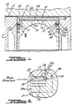
- the composite piston 10 comprises a piston member 15, a ceramic facing member 14, and a carrier member 16.
- the carrier member separates the facing member from the piston member, but secures it for conjoint movement with the piston member by way of portion 17 which is fused and locked to a grooved wall 18 of the piston member (see Figure 2).
- the ceramic facing member is exposed upwardly to aid in defining a combustion chamber 19 in cooperation with the engine head 12 and the block 11, gasket 13 being interposed between the head and block to assure sealing of the internal combustion chamber 19.
- the sides of the composite piston 10 are adapted to reciprocate along the interior walls of an engine block 11, contact therebetween being by metallic seal rings 23 on the piston member bearing against the block.
- the method by which the piston assembly is fabricated is as follows.
- the members of the composite piston are formed.
- First the ceramic facing member 14 is formed of a material preferably selected from the group consisting of zirconia and aluminia, each having a high thermal expansion coefficient for ceramics, typically about 58 ⁇ 65x10 -6 cm/cm/°C (5.0-5.6x10⁻⁶ in/in/°F).
- the forming may be carried out by conventional ceramic powder pressure sintering techniques.
- the die or mold for the sintering of the ceramic powder is shaped to define a disc having a diameter typically in the range of 2.5-15 cm (1-6 inches) and a thickness of about .25-1.25 cm (.1-.5 inche).
- the facing member is preferably sized to extend over a major portion of the top of 15b of the piston member.
- the piston member 15 is formed typically by casting or by forging, and is comprised of a material selected from the group consisting of aluminum, plastic, and magnesium, each having a density of less than 4.15 g/cm 3 (.15 Ib/in 3 ).
- the thermal expansion coefficient of aluminum and magnesium range from 116-162x10- 6 cm/cm/°C (10.0 for alloyed aluminum) to 14.0 (for pure magnesium)x10- 6 in/in/°F).
- the piston member has a narrowed neck portion 15a with an upper side wall 20 spaced radially inwardly from its outer cylindrical side wall 21.
- the side wall 21 has grooves 22 defined therein for carrying split metallic piston rings 23.
- an insert ring 24 is cast in place at the time the aluminum piston is formed.
- Such ring can be formed by casting, forging, or stamping, or other conventional techniques.
- Such ring is preferably comprised of a material having a coefficient of thermal expansion intermediate that of the piston material and the carrier member.
- such ring is comprised of nickel resist iron, an iron that can be fabricated with a varying thermal expansion coefficient ranging from 32 ⁇ 116x10 -6 cm/cm/°C (2.8 to 10x10- 6 in/in/°F). Accordingly, the nickel resist iron can be designed to have a desirable thermal expansion characteristic so it can be matched to the assembly.
- the insert ring has a radially inwardly located neck 25 presenting a surface 25a aligned with the outer surface of neck portion 15a of the piston.
- the ring has a radially extending flange 26, the flange extending outwardly to an extent slightly beyond the side wall 21 of the piston member with surface 24a acting as an upper shoulder of the piston member.
- the carrier member 16 is formed by casting or forging or other conventional techniques and is constituted of a material selected from stainless steel and cast iron, each having a low coefficient of thermal expansion 70-81x10- 6 cm/cm/°C (ranging from 6.0-7.0 10- 6 in/in/°F) for a metal; each differs from the coefficient of thermal expansion of the ceramic by no greater than 23x10- 6 cm/cm/°C (2.0x10 -6 in/in/°F).
- the carrier member has one side 16a adapted to sit on surface 15b of the piston and to wrap over and depend along at least a portion of the piston member side 20. This is accomplished here by use of a depending annular flange 26 adapted to fit snuggly about the upper neck portion 15a of the piston member.
- the carrier member has an opposite side 16b provided with means 28 to securely receive the facing member for conjoint movement therewith (here an annular flange).
- An annular grooved wall 18 is machined in the neck 25 of the ring 24 (surface 25a being aligned with upper side wall 20 of the piston member).
- the grooved wall is disposed at a location radially inwardly a portion of the carrier member when the latter is in the wrapped condition; that is, grooved wall 18 is radially inwardly flange 26 as it depends downwardly about piston member neck 15a.
- the grooved wall 18 has a depth of no less than .025 cm (.010 inch) and a width of no less than .05 cm (.20 inch).
- the carrier member is fitted or wrapped about the neck 15a of the piston member, preferably by use of a shrink fit, so as to have a tight mechanical relationship therewith.
- the depending flange 26 of the carrier member fits snuggly to surround the neck 15a and the upper portion of the nickel resist ring 24 and be radially aligned with the grooved wall 18.
- a high energy beam is then directed across a zone 29 of the carrier member (flange 26) radially aligned with the grooved wall 18 in a manner to melt portion 30 of the carrier member intersected by the beam and cause the melted portion to flow into the grooved wall 18 to fill the groove.
- the high energy beam is preferably comprised of an electron beam having an energy level in the range of 3000-6000 watts, and effective to raise the temperature of the intersected carrier member to melting within a matter of about .7 minutes without melting of the cast-in-place ring 24.
- the resulting solidified material that had flowed into the grooved wall forms a mechanical lock at 17 between the carrier member and the nickel resist ring (the latter forming a part of the piston member).
Landscapes
- Engineering & Computer Science (AREA)
- Mechanical Engineering (AREA)
- General Engineering & Computer Science (AREA)
- Chemical & Material Sciences (AREA)
- Combustion & Propulsion (AREA)
- Pistons, Piston Rings, And Cylinders (AREA)
Abstract
Claims (17)
Applications Claiming Priority (1)
| Application Number | Priority Date | Filing Date | Title |
|---|---|---|---|
| PCT/US1983/002035 WO1985002804A1 (fr) | 1983-12-27 | 1983-12-27 | Pistons composites et leur procede de fabrication |
Publications (3)
| Publication Number | Publication Date |
|---|---|
| EP0167523A1 EP0167523A1 (fr) | 1986-01-15 |
| EP0167523A4 EP0167523A4 (fr) | 1988-01-11 |
| EP0167523B1 true EP0167523B1 (fr) | 1990-04-04 |
Family
ID=22175646
Family Applications (1)
| Application Number | Title | Priority Date | Filing Date |
|---|---|---|---|
| EP84900471A Expired EP0167523B1 (fr) | 1983-12-27 | 1983-12-27 | Pistons composites et leur procede de fabrication |
Country Status (5)
| Country | Link |
|---|---|
| US (1) | US4592268A (fr) |
| EP (1) | EP0167523B1 (fr) |
| JP (1) | JPS61500838A (fr) |
| DE (1) | DE3381402D1 (fr) |
| WO (1) | WO1985002804A1 (fr) |
Families Citing this family (11)
| Publication number | Priority date | Publication date | Assignee | Title |
|---|---|---|---|---|
| US4819595A (en) * | 1981-03-30 | 1989-04-11 | Pfefferle William C | Method of operating catalytic ignition cyclic engines |
| GB8622538D0 (en) * | 1986-09-18 | 1986-10-22 | Ae Plc | Pistons |
| GB8714287D0 (en) * | 1987-06-18 | 1987-07-22 | Ae Plc | Pistons |
| KR900006661A (ko) * | 1988-10-25 | 1990-05-08 | 고하라 도시히토 | 시래믹스-금속의 마찰 압접체 및 그것으로 이루어지는 시래믹스 따로 만들어 붙임 피스턴 |
| JPH0668258B2 (ja) * | 1989-09-13 | 1994-08-31 | いすゞ自動車株式会社 | 断熱ピストンの構造 |
| GB2271521B (en) * | 1992-10-06 | 1996-01-31 | Metalock | Reconditioning engine parts |
| US6615470B2 (en) * | 1997-12-15 | 2003-09-09 | General Electric Company | System and method for repairing cast articles |
| US6863759B2 (en) | 2001-01-24 | 2005-03-08 | M Cubed Technologies, Inc. | Methods for making composite bonded structures |
| DE10353473B4 (de) * | 2003-11-15 | 2007-02-22 | Daimlerchrysler Ag | Bauteil einer Brennkraftmaschine und Verfahren zu dessen Herstellung |
| DE102004057284A1 (de) * | 2004-11-26 | 2006-06-14 | Fev Motorentechnik Gmbh | Leichtbaukolben für thermisch hochbelastete Kolben |
| US9212621B2 (en) | 2013-03-13 | 2015-12-15 | Federal-Mogul Corporation | Piston and method of construction thereof |
Family Cites Families (39)
| Publication number | Priority date | Publication date | Assignee | Title |
|---|---|---|---|---|
| GB160790A (en) * | 1920-03-27 | 1921-12-22 | Fried Krupp Germaniawerft Ag | Improvements in connecting weldable metal articles with articles which cannot be welded or are difficult to weld |
| US1462655A (en) * | 1922-08-30 | 1923-07-24 | Charles W Philip | Piston and method of manufacturing the same |
| US1490849A (en) * | 1922-11-20 | 1924-04-15 | Charles W Philip | Method of making pistons |
| FR578316A (fr) * | 1923-05-11 | 1924-09-23 | Système permettant de diminuer les chaleurs perdues dans les moteurs à combustion ou à explosion | |
| US1559439A (en) * | 1925-01-16 | 1925-10-27 | Edward W Kapraun | Internal-combustion engine |
| US1771771A (en) * | 1927-06-20 | 1930-07-29 | Donald J Campbell | Aluminum head piston |
| US2246942A (en) * | 1937-08-13 | 1941-06-24 | Janney Cylinder Company | Piston |
| US2478294A (en) * | 1945-08-29 | 1949-08-09 | Madsen Tage | Pistons for combustion, steam, and other engines |
| US2657961A (en) * | 1950-03-15 | 1953-11-03 | Maschf Augsburg Nuernberg Ag | Piston for internal-combustion engines |
| US2833264A (en) * | 1954-12-22 | 1958-05-06 | John Altorfer | Internal combustion engine |
| US3189010A (en) * | 1963-11-21 | 1965-06-15 | Continental Aviat & Eng Corp | Piston for internal combustion engine |
| US3190273A (en) * | 1964-01-03 | 1965-06-22 | Continental Aviat & Eng Corp | Piston for internal combustion engine |
| US3354793A (en) * | 1964-11-26 | 1967-11-28 | Mahle Kg | Piston for internal combustion engines |
| DE1262071B (de) * | 1965-03-13 | 1968-02-29 | Mahle Kg | Kolben fuer Brennkraftmaschinen mit einem im Bereich der Ringzone liegenden, ringfoermigen Hohlraum |
| GB1277579A (en) * | 1968-07-15 | 1972-06-14 | Wellworthy Ltd | Pistons |
| US3794334A (en) * | 1970-05-11 | 1974-02-26 | Ramsey Corp | Piston ring facings |
| US3697091A (en) * | 1970-05-11 | 1972-10-10 | Ramsey Corp | Piston ring facings |
| US3895432A (en) * | 1973-07-04 | 1975-07-22 | Siemens Ag | Method of electrically joining together two bimetal tubular superconductors |
| JPS5059241A (fr) * | 1973-09-28 | 1975-05-22 | ||
| US3914574A (en) * | 1973-10-01 | 1975-10-21 | Wellworthy Ltd | Fabricated piston with sprayed groove |
| US3995357A (en) * | 1974-12-16 | 1976-12-07 | Caterpillar Tractor Co. | Integrally cast bearing, method and apparatus for making same |
| US4074616A (en) * | 1975-09-02 | 1978-02-21 | Caterpillar Tractor Co. | Aluminum piston with steel reinforced piston ring grooves |
| DE2639294C2 (de) * | 1976-09-01 | 1982-05-13 | Mahle Gmbh, 7000 Stuttgart | Gepreßter Aluminiumkolben für Verbrennungsmotoren mit Einlagen aus einem anderen Werkstoff |
| JPS54141209U (fr) * | 1978-03-27 | 1979-10-01 | ||
| JPS54163208A (en) * | 1978-06-15 | 1979-12-25 | Toyota Motor Co Ltd | Builttup piston for engine |
| US4419925A (en) * | 1978-06-15 | 1983-12-13 | Toyota Jidosha Kogyo Kabushiki Kaisha | Assembled piston for engine |
| DE2835332C2 (de) * | 1978-08-11 | 1982-06-24 | Messer Griesheim Gmbh, 6000 Frankfurt | Kolben mit einem Körper aus einer Aluminiumlegierung |
| US4245611A (en) * | 1978-09-05 | 1981-01-20 | General Motors Corporation | Ceramic insulated engine pistons |
| DE2914456A1 (de) * | 1979-04-10 | 1980-10-23 | Schmidt Gmbh Karl | Gebauter kolben fuer brennkraftmaschinen |
| GB2094934B (en) * | 1979-07-19 | 1983-06-02 | Ass Eng France | The reinforcement of piston ring grooves |
| SE433376B (sv) * | 1979-10-22 | 1984-05-21 | Saab Scania Ab | Kolvmotor med vermeisolerat forbrenningsrum |
| US4306489A (en) * | 1979-11-01 | 1981-12-22 | Exxon Research & Engineering Co. | Composite piston |
| DE2950778C2 (de) * | 1979-12-17 | 1982-04-29 | Johannes R. Dipl.-Ing. 8000 München Smirra | Verfahren und Einrichtung zur Herstellung eines Verschlußkörpers für ein Konus-Labyrinthventil |
| JPS572444A (en) * | 1980-06-05 | 1982-01-07 | Aisin Seiki Co Ltd | Manufacture of ceramic incorporated type engine piston |
| JPS572445A (en) * | 1980-06-06 | 1982-01-07 | Aisin Seiki Co Ltd | Manufacture of ceramic incorporated type engine piston |
| US4404935A (en) * | 1981-04-27 | 1983-09-20 | Kyocera International, Inc. | Ceramic capped piston |
| US4404262A (en) * | 1981-08-03 | 1983-09-13 | International Harvester Co. | Composite metallic and refractory article and method of manufacturing the article |
| US4440069A (en) * | 1982-06-11 | 1984-04-03 | Standard Oil Corporation (Indiana) | Composite piston and process |
| EP0167526B1 (fr) * | 1983-12-27 | 1990-04-04 | Ford Motor Company Limited | Procede et dispositif permettant de modifier la chambre de combustion d'un moteur pour qu'elle accepte des revetements ceramiques |
-
1983
- 1983-12-27 WO PCT/US1983/002035 patent/WO1985002804A1/fr not_active Ceased
- 1983-12-27 EP EP84900471A patent/EP0167523B1/fr not_active Expired
- 1983-12-27 DE DE8484900471T patent/DE3381402D1/de not_active Expired - Lifetime
- 1983-12-27 US US06/617,446 patent/US4592268A/en not_active Expired - Fee Related
- 1983-12-27 JP JP84500558A patent/JPS61500838A/ja active Pending
Also Published As
| Publication number | Publication date |
|---|---|
| EP0167523A1 (fr) | 1986-01-15 |
| WO1985002804A1 (fr) | 1985-07-04 |
| US4592268A (en) | 1986-06-03 |
| DE3381402D1 (de) | 1990-05-10 |
| EP0167523A4 (fr) | 1988-01-11 |
| JPS61500838A (ja) | 1986-05-01 |
Similar Documents
| Publication | Publication Date | Title |
|---|---|---|
| EP0261726B1 (fr) | Pistons | |
| US4562799A (en) | Monolithic ceramic cylinder liner and method of making same | |
| EP0118204B1 (fr) | Renforcement de pistons d'aluminium ou d'alliage d'aluminium | |
| US4334507A (en) | Piston for an internal combustion engine and method for producing same | |
| US4530341A (en) | Piston engine having at least one heat-insulated combustion chamber, and parts for said engine | |
| EP0167526B1 (fr) | Procede et dispositif permettant de modifier la chambre de combustion d'un moteur pour qu'elle accepte des revetements ceramiques | |
| US4592268A (en) | Method of making and apparatus for composite pistons | |
| US4495684A (en) | Process of joining a ceramic insert which is adapted to be embedded in a light metal casting for use in internal combustion engines | |
| GB2039666A (en) | Diesel engine oil cooled piston | |
| US4524732A (en) | Cylinder head of a piston engine | |
| US4676207A (en) | Auxiliary combustion chamber | |
| EP0155159B1 (fr) | Piston pour moteur à combustion interne et son procédé de fabrication | |
| EP0295481A2 (fr) | Pistons | |
| US4649806A (en) | Composite ceramic/metal piston assembly and method of making | |
| US4590901A (en) | Heat insulated reciprocating component of an internal combustion engine and method of making same | |
| US4522171A (en) | Pre-combustion or turbulence chamber for internal combustion engines | |
| US4972898A (en) | Method of forming a piston containing a cavity | |
| US4506593A (en) | Piston head structure | |
| JPH07189805A (ja) | 燃焼窪みを備えた軽金属ピストン及び該ピストンを製造する方法 | |
| US4651630A (en) | Thermally insulating pistons for internal combustion engines and method for the manufacture thereof | |
| US4741253A (en) | Piston for internal combustion engines | |
| CA1230274A (fr) | Methode de fabrication d'un piston en materiau composite, et appareil connexe | |
| US7069881B2 (en) | Cooled ring carrier for a piston | |
| US4930546A (en) | Heat-insulating metal-ceramic structure | |
| US4516480A (en) | Piston ring for endothermic motors having an improved flame damper ring |
Legal Events
| Date | Code | Title | Description |
|---|---|---|---|
| PUAI | Public reference made under article 153(3) epc to a published international application that has entered the european phase |
Free format text: ORIGINAL CODE: 0009012 |
|
| 17P | Request for examination filed |
Effective date: 19850828 |
|
| AK | Designated contracting states |
Kind code of ref document: A1 Designated state(s): DE GB Designated state(s): DE GB |
|
| A4 | Supplementary search report drawn up and despatched |
Effective date: 19880111 |
|
| 17Q | First examination report despatched |
Effective date: 19881212 |
|
| GRAA | (expected) grant |
Free format text: ORIGINAL CODE: 0009210 |
|
| AK | Designated contracting states |
Kind code of ref document: B1 Designated state(s): DE GB |
|
| REF | Corresponds to: |
Ref document number: 3381402 Country of ref document: DE Date of ref document: 19900510 |
|
| REG | Reference to a national code |
Ref country code: GB Ref legal event code: 746 |
|
| PLBE | No opposition filed within time limit |
Free format text: ORIGINAL CODE: 0009261 |
|
| STAA | Information on the status of an ep patent application or granted ep patent |
Free format text: STATUS: NO OPPOSITION FILED WITHIN TIME LIMIT |
|
| 26N | No opposition filed | ||
| PGFP | Annual fee paid to national office [announced via postgrant information from national office to epo] |
Ref country code: GB Payment date: 19941122 Year of fee payment: 12 |
|
| PGFP | Annual fee paid to national office [announced via postgrant information from national office to epo] |
Ref country code: DE Payment date: 19941208 Year of fee payment: 12 |
|
| PG25 | Lapsed in a contracting state [announced via postgrant information from national office to epo] |
Ref country code: DE Effective date: 19951117 |
|
| PG25 | Lapsed in a contracting state [announced via postgrant information from national office to epo] |
Ref country code: GB Effective date: 19951227 |
|
| GBPC | Gb: european patent ceased through non-payment of renewal fee |
Effective date: 19951227 |