EP0167561B1 - Method and apparatus for surface diagnostics - Google Patents
Method and apparatus for surface diagnostics Download PDFInfo
- Publication number
- EP0167561B1 EP0167561B1 EP85900261A EP85900261A EP0167561B1 EP 0167561 B1 EP0167561 B1 EP 0167561B1 EP 85900261 A EP85900261 A EP 85900261A EP 85900261 A EP85900261 A EP 85900261A EP 0167561 B1 EP0167561 B1 EP 0167561B1
- Authority
- EP
- European Patent Office
- Prior art keywords
- sample
- ionization
- ionizing
- resonant
- further characterized
- Prior art date
- Legal status (The legal status is an assumption and is not a legal conclusion. Google has not performed a legal analysis and makes no representation as to the accuracy of the status listed.)
- Expired
Links
Images

Classifications
-
- H—ELECTRICITY
- H10—SEMICONDUCTOR DEVICES; ELECTRIC SOLID-STATE DEVICES NOT OTHERWISE PROVIDED FOR
- H10P—GENERIC PROCESSES OR APPARATUS FOR THE MANUFACTURE OR TREATMENT OF DEVICES COVERED BY CLASS H10
- H10P72/00—Handling or holding of wafers, substrates or devices during manufacture or treatment thereof
- H10P72/06—Apparatus for monitoring, sorting, marking, testing or measuring
- H10P72/0604—Process monitoring, e.g. flow or thickness monitoring
-
- H—ELECTRICITY
- H10—SEMICONDUCTOR DEVICES; ELECTRIC SOLID-STATE DEVICES NOT OTHERWISE PROVIDED FOR
- H10P—GENERIC PROCESSES OR APPARATUS FOR THE MANUFACTURE OR TREATMENT OF DEVICES COVERED BY CLASS H10
- H10P72/00—Handling or holding of wafers, substrates or devices during manufacture or treatment thereof
- H10P72/06—Apparatus for monitoring, sorting, marking, testing or measuring
Definitions
- the invention relates to techniques for local analysis of surfaces; more particularly, it is directed to techniques for mass spectral analysis of species of matter on, or forming a part of, a surface.
- the specimen to be examined is placed in a high-vacuum chamber and bombarded by a probe beam of one kind or another.
- the probe beam removes a sample of matter from the surface, at least a portion of which is ionized in the process of removal or subsequent thereto.
- the ionized sample is then subjected to mass spectral analysis.
- Examples of known techniques for surface mass spectral analysis include laser microprobe methods and secondary ion mass spectrometry. Both of these methods contain undesirable limitations.
- Laser microprobe mass spectrometry uses a focused high-intensity laser to irradiate a surface directly and blow off large amounts of material, only a small fraction of which is ionized as it departs from the surface.
- the high-intensity laser results in highly destructive sampling of the surface; the intense laser pulse used in typical instruments forms craters of 0.1 to 1.0 micrometers in depth and is therefore not truly surface-sensitive.
- the laser microprobe technique is also difficult to model because ionization efficiencies depend sensitively on the various collisional processes occurring in the laser-generated plasma at the surface.
- SIMS secondary ion mass spectrometry
- the surface under examination is bombarded with an ion beam or fast neutral beam, which sputters a sample of ionized and neutral matter from the surface.
- quantitative analytical information is difficult to derive from the SIMS method because the physical processes that determine the ionization probability of the sputtered matter are not, as a rule, well understood and because ionization probabilities depend sensitively on surface composition (so-called matrix effects) and cleanliness (so-called chemical enhancement effects).
- matrix effects surface composition
- chemical enhancement effects chemical enhancement effects
- PCT application WO A1 83.02572 to Hurst discloses methods of analyzing, among other things, the elemental composition of solid surfaces.
- This reference is specifically directed to an ultra sensitive method, which is at the same time highly selective.
- the disclosed resonance-ionization technique is used to detect extremely small quantities of a previously known compound in a larger sample. It is to be noted that the Hurst reference is limited to resonant photoionization.
- the present invention provides an extremely reliable and versatile method and apparatus for detecting and distinguishing unknown species of matter at extremely low surface concentrations. It has been discovered that the process of non-resonant photoionization may be utilized to make a practical instrument capable of highly sensitive surface diagnostics and free of the restrictions imposed by the above-mentioned methods.
- a probe beam such as an ion beam, electron beam, or laser beam is directed to the surface under examination to cause a sample of material to be removed from the surface.
- a beam of electromagnetic radiation which may be provided by an untuned, high-intensity laser, is then directed to a spatial region proximate to the surface causing non-resonant ionization of the removed surface sample within the beam of radiation. It has been discovered that within the practical limits of readily achievable laser intensities this beam may be given sufficient intensity to induce a high degree of non-resonant, and hence non-selective, photoionization of the sample.
- the ionized sample is then subjected to mass spectral analysis to determine the nature of the species included therein.
- a probe beam means is provided for directing a probe beam at the surface of the specimen so as to cause a sample to be ejected into the evacuation chamber.
- Ionizing beam means provides a non-resonant ionizing beam of radiation which is directed at a spatial region (referred to as the ionization region) above the surface.
- the ionizing beam has an intensity sufficient to induce non- resonant photoionization of the sample found in the ionizing region.
- Means is provided within the evacuation chamber for accelerating the ionized sample into a region including means for mass analysis of the ions.
- a preferred mass analysis means compatible with pulsed laser ionization provides an ion drift region, so as to enable time-of-flight analysis of the ionized sample.
- a preferred embodiment of the apparatus includes ion reflector means disposed within the drift region for effectively compensating for undesirable spreading of the arrival times caused by the initial ion velocity distributions.
- Detection means is disposed within the evacuation chamber for detecting the ions emerging from the drift region.
- the invention provides a number of advantages which have not previously been found in a single instrument.
- the method and apparatus according to the invention are not restricted to the investigation of atomic species or simple molecular species having known excitation and ionization spectra.
- the invention may be applied to a wide variety of compounds of interest including con- tami p ated or doped substrates, adsorbed or reacted overlayers, or even biological samples which have been precipitated onto or otherwise applied to a surface. All masses can be investigated simultaneously with a single (untuned) laser wavelength. Every atom is accessible to ionization by the present technique.
- the probe beam intensity may be adjusted so as to produce minimal damage to the surface under examination. Notwithstanding the reduced probe beam intensity, the nonresonant ionizing beam produces sufficient ionization of the sample that even extremely low concentrations of matter can be detected.
- the method and apparatus of the invention are sufficiently reliable and accurate, and sufficiently nondestructive in the surface-removal step, that it is possible to monitor changes in concentrations of species in the course of chemical reactions taking place on the surface.
- the nonresonant photoionization method of the present invention requires a probe beam for removing a sample of material from the surface under examination and a separate high-intensity nonresonant ionizing beam of radiation.
- nonresonant ionizing beam of radiation means a beam of electromagnetic radiation which has not been tuned to a predetermined wavelength associated with the specimen under examination.
- the probe beam for removing the sample from the surface may be provided, for example, by an electron beam, an ion beam, a fast atom beam, or a laser beam.
- the separation of the sample-removal step from the ionization step allows independent control of the sample removal and ionization processes.
- the probe beam can be directed to a localized region of the surface and adjusted in intensity so as to scan the depth from which the sample is removed (so-called depth profiling) or to scan the surface area over which the sample is removed (so-called microscopy). In this manner mono-layers of particles adsorbed on the surface may be sampled from extremely localized regions.
- Ionization of the sample under examination may occur through single-photon and multi- photon processes. Ionization occurs by means of a multi-photon mechanism at a lower photon energy than by means of a single-photon mechanism, but the multi-photon approach requires higher overall intensities. In fact, it has generally been believed that a resonance condition is required in the multi-photon approach to achieve sufficient ionization for subsequent mass spectral analysis. In the present invention it has been discovered that ionization of the sample removed from the surface can be saturated in the ionizing region with nonresonant multi-photon photoionization.
- the ionizing beam for nonresonant multi- photon ionization may be provided by a laser having a power density in the range of 10 6 to 10 12 W/cm 2 .
- the laser is advantageously pulsed for time-of-flight mass spectrometry, the pulses having a period of about 10- 8 seconds.
- pulses with at least about 10 12 photons per pulse are needed for efficient ionization.
- a mass spectrum was derived from a sputter-cleaned surface of an NBS standard copper specimen of known bulk composition.
- a pulsed 3-keV Ar + ion probe beam hitting the surface over an area of about 0.1 cm 2 and a 10 pulse/sec, 20 millijoule/pulse KrF (248nm) laser ionizing beam focused by a 40 cm focal length lens to a spot 1 mm above the specimen surface, impurity isotopes at concentrations from 1 to 10 ppm (parts per million) were easily observed in an experiment that removed a total of about 10 -10 g, equivalent to 0.01 monolayer, from the copper sample.
- the detector was estimated to collect one ion for every 10 4- 10 5 surface atoms removed by the probe beam.
- sputtered neutral dimers are also observed as dimer ions after photoionization by the laser. These include, of course, C U2 but also CuAg even though each of the two isotopes of Ag is only approximately 50 ppm of the Cu sample.
- doubly charged ions e.g Pt ++ , W ++ , Ta++, Cu ++ , have also been observed, which indicates strongly saturated conditions for the singly ionized entities.
- hydrocarbon molecules adsorbed on catalytically active metal surfaces have been observed.
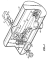
- Probe beam means 13 provides a probe beam which is directed to a localized area of the surface 12.
- the probe beam means 13 is illustrated schematically in Figure 1. It will generally include a beam source 14 and means 15 for directing the probe beam generated by source 14 onto the localized area of the surface 12 under examination.
- Beam source 14 may be provided, for example, by an electron gun or ion gun or by a laser.
- the construction of such beam sources is conventional and is well known to those skilled in the art, for example, from electron beam desorption, ion beam sputtering, or laser microprobe techniques.
- means 15 for directing the beam onto the surface 12 may be provided by an assembly comprising an electrostatic or magnetic lens and horizontal and vertical electrostatic deflection plates.
- means 15 will generally be provided by a system of mirrors and lenses. In focusing the ion beam or laser beam onto a localized region of the surface 12, the means 15 enhances the power density of the beam at the surface, which allows a lower intensity ion beam or laser to be used for the beam source 14.
- Means 17 provides an ionizing beam of radiation which is directed to a region proximate to the surface 12 so as to irradiate a substantial portion of the sample removed by the probe beam.
- the means 17 will generally include a high-intensity light source 18, a focusing lens system 19 and an iris 20 for use in defining the position of the ionizing beam.
- Beam source 18 will typically be provided by a high-intensity laser or an assembly of lasers and optical materials and components coupled together to achieve sufficiently high power for saturation of the ionization of the sample under investigation.
- the specimen under investigation is housed within an evacuation chamber 22 which is provided with pumping means, e.g., a port 23 adapted for connection to a vacuum pump (not shown).
- pumping means e.g., a port 23 adapted for connection to a vacuum pump (not shown).
- the probe beam is provided by a laser beam
- the laser is mounted outside of chamber 22, which is provided with an additional window (not shown) through which the beam enters the chamber.
- probe beam source 14 may be contained in an adjacent chamber evacuated by additional vacuum pumps (not shown) and connected to chamber 22 by a small aperture through which the ion beam enters.
- evacuation chamber 22 is provided with diametrically opposed windows 24 and 25, through which the ionizing beam of radiation is projected.
- the ionizing beam means 17 is mounted outside evacuation chamber 22, and the ionizing beam is directed through window 24 to the ionization region proximate to the surface 12 under investigation.
- the ionizing beam continues through window 25, passes through position-defining iris 26, and is received by detector 27, which serves to monitor the light intensity.
- mounting means 28 is provided within evacuation chamber 22 for mounting a plurality of specimens. In this way several specimens may be investigated without having to break the vacuum within chamber 22.
- Mounting means 28 is connected to a position manipulator (not shown) and is accessible through an associated specimen introduction system (not shown).
- Evacuation chamber 22 also includes mass spectrometer means, indicated generally at 31, for mass analysis of the sample ionized by the ionizing beam.
- the preferred embodiment utilizes a time-of-flight mass spectrometer.
- Other types of mass spectrometers for example, the Mattauch-Herzog focal plane mass spectrometer, may be employed as well.
- evacuation chamber 22 includes gridded electrostatic extraction network 32, electrostatic focusing lens 33, deflection plates 34, field-free region 36, ion reflection means 37, and particle detector 38.
- the arrangement of Figures 1 and 2 provides for two alternative placements of the ionizing laser beam.
- the beam When the specimen under examination has an electrically conducting surface, the beam may be directed close to the surface at the position indicated at 39 in Figure 2.
- the electrostatic extraction network 32 is not energized. Instead, the surface of the specimen is floated at a high potential to repel the photo-ions through the network 32 and into the time-of-flight drift region 36.
- the ionizing laser beam is directed between two grids of the electrostatic extraction network 32, as illustrated in Figure 2 at 40. In this arrangement it is the network 32 which repels the photo-ions into drift region 36.
- Windows 24 and 25 are large enough to allow the laser beam to be directed to either of the positions 39 or 40.
- the photo-ions After extraction from the ionizing region, the photo-ions are focused by electrostatic focusing lens 33 and aligned by deflection plates 34.
- immersion lens means could be used to accelerate and direct the photo-ions.
- the ions exiting from the drift region would be received directly by a detector.
- ions leaving the drift region are reflected by ion reflection means 37 and traverse the field-free drift region 36 once again to enter detector 38.
- the detector is a particle multiplier, for example, a microchannel plate which is apertured so that only ions coming from the direction of reflecting means 37 will be detected.
- the ion reflector 37 comprises outer reflector grid 41 at ground potential, middle reflector grid 42, providing a decelerating potential, an assembly of electrostatic guard rings 43 connected by resistors to insure a uniform field in the reflector region, and a back reflector grid 44, providing a reflecting potential.
- the embodiment of Figure 1 also includes an auxiliary particle detector 46 of like construction to particle detector 38 positioned to detect particles passing entirely through reflector means 37.
- auxiliary particle detector 46 of like construction to particle detector 38 positioned to detect particles passing entirely through reflector means 37.
- the use of an ion reflector in time-of-flight mass spectrometry is known in the art.
- the construction of such an ion reflector is disclosed, for example, by D.M. Lubman et al., Analytical Chemistry, Vol. 55, No. 8 (1983) pp. 1437-40 and by G.S. Janes in U.S. Patent No. 3,727,047.
- the ion reflector provides for high resolution over a wide range of charge-to-mass ratios by compensating for the spread in the times at which ions would otherwise arrive at detector 38 due to their initial velocity distribution.
- the ion reflector is especially advantageous in the present invention to provide greater resolution of the many components which may be non-selectively ionized by the nonresonant beam.
- a further advantage of the ion reflector in the present invention is the ability it affords for.distinguishing metastable molecular ions that dissociate along the path in drift region 36 before entering the reflector.
- the potential of the back reflector grid 44 can be adjusted so that the parent ions pass through while the decay products of the lower-energy metastable ions are reflected for detection by detector 38.
- the use of the ion reflector enables the instrument to take greater advantage of the nonresonant beam's capacity for nonselective ionization.
- a further advantage of the ion reflector in the present invention which has not been appreciated in surface analysis techniques, is the discrimination between photo-ions and secondary ions described in the preceding paragraph.
- Pulse generator 51 provides a master repetition-rate signal, for example, a ten Hertz signal for controlling the pulse repetition rate of the probe and/or ionizing beams.
- the master signal from pulse generator 51 is applied to three-channel delay generator 52.
- Channel 1 of delay generator 52 provides a trigger signal to probe beam pulsing means 53.
- the pulsing means 53 is operatively associated with the probe beam means for producing a probe beam pulse having a desired width.
- Channel 2 of delay generator 52 provides a trigger signal to ionizing beam pulsing means 54, which is operatively associated with the ionizing beam source to provide a desired pulse delay. Suitable pulsing means are well known to those skilled in the art from their use in other pulsed ion beam or pulsed electron beam applications and pulsed laser applications and will not be described further.
- Channel 3 of delay generator 52 provides a trigger signal to transient recorder 56. The trigger signal from channel 3 sets the time position for the initial channel of the transient recorder in a time-of-flight measurement.
- Block 57 represents the signal-generating portion of the particle detector, for example, the anode of a multichannel plate particle multiplier.
- the signal from block 57 is passed through a variable highfrequency response signal attenuator 58, which may be of conventional design, and is amplified by fast linear amplifier 59.
- the amplified signal is applied to transient recorder 56, which may be provided by a fast A/D converter. With a laser pulse width of 5-10 nanoseconds, attenuator 58 and amplifier 59 should have bandwidths greater than 150 megahertz to achieve acceptable resolution.
- the time-of-flight measurement data registered by transient recorder 56 are entered into computer 60 for storage and analysis. Methods of analysis of time-of-flight measurement data are well known to those skilled in the art and do not form a part of the present invention.
- Signal attenuator 58 is helpful in comparing different components present in greatly differing concentrations. For a sufficiently large signal associated with a component present in high concentration, amplifier 59 will tend to saturate, which will bias the ratio of components present. Attenuator 58 reduces large signals by a known factor so as to allow the normalization of small signals to large ones.
- the trigger signal indicating the time zero for a time-of-flight measurement may alternatively be provided by a pulse suitably delayed after initiation by a pulse from a photo diode positioned to detect light from the laser beam.
- Start and stop pulses generated by the photo diode and by the particle detector, respectively, can be applied with suitable time delay of the start pulse to a time-to- digital converter for time-of-flight measurement in an alternative approach for examining mass ranges where the ion arrival rate is low (less than 1 ion per laser pulse).
- the apparatus and method of the present invention may be utilized in a variety of surface and diagnostic applications.
- the invention provides sufficient resolution and is sufficiently non-destructive that it may be used to monitor chemical reactions taking place on the surface.
- the invention is also suited for in situ diagnostics of integrated circuit components.
- the method. described herein may be combined with standard ion milling techniques to achieve depth profiling of IC chips. With a focused probe beam the method and apparatus can also be used as a microscope to reveal the composition of topographical features.
- Adsorbed molecules, including radical species can be detected in circumstances as diverse as heterogeneous catalysis, chemical agents monitoring, and analysis of biological molecules.
- the ionizing laser power density may be varied over a range to examine fragmentation patterns of -biological or other complex molecules.
- Angular distributions of atoms and molecules removed from the surface by the probe beam may be monitored by controlling the position at which the probe beam strikes the surface and its relation to the location of the ionization volume.
- the pulsed mode of operation may be .used to monitor kinetic energy distributions of desorbing or sputtered species by varying the time delay between channel 1 and 2 of delay generator 52 in Figure 3.
- the velocity of a particle removed from the surface and traveling toward the ionization region will be inversely proportional to the time of flight from the localized region under examination to the ionization region.
- the probe beam pulse width and the width of the ionization region may be made sufficiently small to achieve good resolution of the kinetic energy distribution.
Landscapes
- Electron Tubes For Measurement (AREA)
- Other Investigation Or Analysis Of Materials By Electrical Means (AREA)
- Analysing Materials By The Use Of Radiation (AREA)
- Investigating Or Analyzing Materials By The Use Of Ultrasonic Waves (AREA)
Applications Claiming Priority (2)
| Application Number | Priority Date | Filing Date | Title |
|---|---|---|---|
| US56494983A | 1983-12-23 | 1983-12-23 | |
| US564949 | 1983-12-23 |
Publications (2)
| Publication Number | Publication Date |
|---|---|
| EP0167561A1 EP0167561A1 (en) | 1986-01-15 |
| EP0167561B1 true EP0167561B1 (en) | 1989-12-06 |
Family
ID=24256568
Family Applications (1)
| Application Number | Title | Priority Date | Filing Date |
|---|---|---|---|
| EP85900261A Expired EP0167561B1 (en) | 1983-12-23 | 1984-09-20 | Method and apparatus for surface diagnostics |
Country Status (10)
| Country | Link |
|---|---|
| EP (1) | EP0167561B1 (da) |
| JP (1) | JP2640935B2 (da) |
| AU (1) | AU570531B2 (da) |
| CA (1) | CA1220879A (da) |
| DE (2) | DE3490595C2 (da) |
| DK (1) | DK161858C (da) |
| FI (1) | FI83463C (da) |
| GB (1) | GB2160014B (da) |
| SE (1) | SE452676B (da) |
| WO (1) | WO1985002907A1 (da) |
Families Citing this family (7)
| Publication number | Priority date | Publication date | Assignee | Title |
|---|---|---|---|---|
| GB2211020A (en) * | 1987-10-10 | 1989-06-21 | Wallach Eric Robert | Microprobe mass analyser |
| US4920264A (en) * | 1989-01-17 | 1990-04-24 | Sri International | Method for preparing samples for mass analysis by desorption from a frozen solution |
| US5019208A (en) * | 1990-03-23 | 1991-05-28 | Air Products And Chemicals, Inc. | Method for determining the depth of permeation of a modifier into the interior of a thermoplastic article |
| DE4036115C2 (de) * | 1990-11-13 | 1997-12-11 | Max Planck Gesellschaft | Verfahren und Einrichtung zur quantitativen nichtresonanten Photoionisation von Neutralteilchen und Verwendung einer solchen Einrichtung |
| US5830655A (en) | 1995-05-22 | 1998-11-03 | Sri International | Oligonucleotide sizing using cleavable primers |
| EP1164203B1 (en) | 1996-11-06 | 2007-10-10 | Sequenom, Inc. | DNA Diagnostics based on mass spectrometry |
| EP0963443B1 (en) | 1996-12-10 | 2006-03-08 | Sequenom, Inc. | Releasable nonvolatile mass-label molecules |
Family Cites Families (8)
| Publication number | Priority date | Publication date | Assignee | Title |
|---|---|---|---|---|
| US3727047A (en) * | 1971-07-22 | 1973-04-10 | Avco Corp | Time of flight mass spectrometer comprising a reflecting means which equalizes time of flight of ions having same mass to charge ratio |
| FR2279093A1 (fr) * | 1974-06-28 | 1976-02-13 | Anvar | Procede et dispositif d'analyse chimique locale des solides |
| JPS54123163A (en) * | 1978-03-16 | 1979-09-25 | Mitsuboshi Belting Ltd | Acrylic rubber composition |
| DE3015352A1 (de) * | 1980-04-22 | 1981-11-05 | Kernforschungsanlage Jülich GmbH, 5170 Jülich | Verfahren und vorrichtung zum spektoskopischen naschweis von an der oberflaeche eines festkoerpers befindlichen elementen |
| JPS58119148A (ja) * | 1982-01-09 | 1983-07-15 | Jeol Ltd | 質量分析装置のイオン源 |
| US4442354A (en) * | 1982-01-22 | 1984-04-10 | Atom Sciences, Inc. | Sputter initiated resonance ionization spectrometry |
| JPS5981854A (ja) * | 1982-10-31 | 1984-05-11 | Shimadzu Corp | 二次イオン質量分析装置 |
| JPS60114753A (ja) * | 1983-11-25 | 1985-06-21 | ジー・サムエル ハースト | 構成元素の定量分析法およびその装置 |
-
1984
- 1984-09-20 EP EP85900261A patent/EP0167561B1/en not_active Expired
- 1984-09-20 WO PCT/US1984/001509 patent/WO1985002907A1/en not_active Ceased
- 1984-09-20 JP JP60500104A patent/JP2640935B2/ja not_active Expired - Lifetime
- 1984-09-20 GB GB08518083A patent/GB2160014B/en not_active Expired
- 1984-09-20 DE DE3490595A patent/DE3490595C2/de not_active Expired - Fee Related
- 1984-09-20 AU AU37447/85A patent/AU570531B2/en not_active Ceased
- 1984-09-20 DE DE19843490595 patent/DE3490595T/de active Pending
- 1984-11-08 CA CA000467335A patent/CA1220879A/en not_active Expired
-
1985
- 1985-08-21 SE SE8503901A patent/SE452676B/sv not_active IP Right Cessation
- 1985-08-22 FI FI853242A patent/FI83463C/fi not_active IP Right Cessation
- 1985-08-22 DK DK381385A patent/DK161858C/da not_active IP Right Cessation
Also Published As
| Publication number | Publication date |
|---|---|
| FI853242A0 (fi) | 1985-08-22 |
| GB8518083D0 (en) | 1985-08-21 |
| FI853242L (fi) | 1985-08-22 |
| CA1220879A (en) | 1987-04-21 |
| EP0167561A1 (en) | 1986-01-15 |
| SE452676B (sv) | 1987-12-07 |
| DE3490595C2 (de) | 1995-10-26 |
| DK161858C (da) | 1992-01-20 |
| FI83463C (fi) | 1991-07-10 |
| JP2640935B2 (ja) | 1997-08-13 |
| GB2160014A (en) | 1985-12-11 |
| AU570531B2 (en) | 1988-03-17 |
| SE8503901L (sv) | 1985-08-21 |
| DK381385A (da) | 1985-08-22 |
| DE3490595T (de) | 1985-11-28 |
| JPS61500866A (ja) | 1986-05-01 |
| AU3744785A (en) | 1985-07-12 |
| GB2160014B (en) | 1987-12-16 |
| SE8503901D0 (sv) | 1985-08-21 |
| DK161858B (da) | 1991-08-19 |
| FI83463B (fi) | 1991-03-28 |
| WO1985002907A1 (en) | 1985-07-04 |
| DK381385D0 (da) | 1985-08-22 |
Similar Documents
| Publication | Publication Date | Title |
|---|---|---|
| US4733073A (en) | Method and apparatus for surface diagnostics | |
| EP0103586B1 (en) | Sputter initiated resonance ionization spectrometry | |
| US4633084A (en) | High efficiency direct detection of ions from resonance ionization of sputtered atoms | |
| Becker et al. | Surface analysis by nonresonant multiphoton ionization of desorbed or sputtered species | |
| WO2008042949A2 (en) | Dual-polarity mass spectrometer | |
| US5382794A (en) | Laser induced mass spectrometry | |
| EP0418785B1 (en) | Method and apparatus for mass spectrometric analysis | |
| EP0744617A2 (en) | Apparatus and method for surface analysis | |
| US6291820B1 (en) | Highly charged ion secondary ion mass spectroscopy | |
| US4864130A (en) | Photo ion spectrometer | |
| US5365063A (en) | Method and apparatus of quantitative non-resonant photoionization of neutral particles and the use of such apparatus | |
| EP0167561B1 (en) | Method and apparatus for surface diagnostics | |
| EP0723282A1 (en) | Laser-assisted particle analysis | |
| Lockyer et al. | Multiphoton ionization mass spectrometry of small biomolecules with nanosecond and femtosecond laser pulses | |
| US5763875A (en) | Method and apparatus for quantitative, non-resonant photoionization of neutral particles | |
| JPS6355846A (ja) | 二次中性粒子質量分析装置 | |
| Pallix et al. | Surface and interface analysis by nonresonant multiphoton ionization of sputtered neutrals | |
| US4855596A (en) | Photo ion spectrometer | |
| US5097125A (en) | Photo ion spectrometer | |
| Axner et al. | Analytical applications of laser-enhanced lonization spectrometry in flames and furnaces | |
| JPH07280752A (ja) | 高感度表面多元素同時質量分析方法 | |
| NL8420306A (nl) | Werkwijze en inrichting voor oppervlakte-diagnose. | |
| JP2001215216A (ja) | 顕微レーザ質量分析計 | |
| Willey et al. | Quantitative high-resolution imaging with sputter-initiated resonance ionization spectroscopy | |
| Gruen et al. | Laser post-ionization secondary neutral mass spectroscopy |
Legal Events
| Date | Code | Title | Description |
|---|---|---|---|
| PUAI | Public reference made under article 153(3) epc to a published international application that has entered the european phase |
Free format text: ORIGINAL CODE: 0009012 |
|
| AK | Designated contracting states |
Designated state(s): BE FR |
|
| 17P | Request for examination filed |
Effective date: 19851223 |
|
| 17Q | First examination report despatched |
Effective date: 19870805 |
|
| GRAA | (expected) grant |
Free format text: ORIGINAL CODE: 0009210 |
|
| AK | Designated contracting states |
Kind code of ref document: B1 Designated state(s): BE FR |
|
| ET | Fr: translation filed | ||
| PLBE | No opposition filed within time limit |
Free format text: ORIGINAL CODE: 0009261 |
|
| STAA | Information on the status of an ep patent application or granted ep patent |
Free format text: STATUS: NO OPPOSITION FILED WITHIN TIME LIMIT |
|
| 26N | No opposition filed | ||
| PGFP | Annual fee paid to national office [announced via postgrant information from national office to epo] |
Ref country code: FR Payment date: 19990902 Year of fee payment: 16 |
|
| PGFP | Annual fee paid to national office [announced via postgrant information from national office to epo] |
Ref country code: BE Payment date: 19990927 Year of fee payment: 16 |
|
| PG25 | Lapsed in a contracting state [announced via postgrant information from national office to epo] |
Ref country code: BE Free format text: LAPSE BECAUSE OF NON-PAYMENT OF DUE FEES Effective date: 20000930 |
|
| BERE | Be: lapsed |
Owner name: SRI INTERNATIONAL Effective date: 20000930 |
|
| PG25 | Lapsed in a contracting state [announced via postgrant information from national office to epo] |
Ref country code: FR Free format text: LAPSE BECAUSE OF NON-PAYMENT OF DUE FEES Effective date: 20010531 |
|
| REG | Reference to a national code |
Ref country code: FR Ref legal event code: ST |