EP0167652A1 - Appareil de commande pour véhicule à moteur - Google Patents
Appareil de commande pour véhicule à moteur Download PDFInfo
- Publication number
- EP0167652A1 EP0167652A1 EP84108179A EP84108179A EP0167652A1 EP 0167652 A1 EP0167652 A1 EP 0167652A1 EP 84108179 A EP84108179 A EP 84108179A EP 84108179 A EP84108179 A EP 84108179A EP 0167652 A1 EP0167652 A1 EP 0167652A1
- Authority
- EP
- European Patent Office
- Prior art keywords
- engine
- ignition angle
- control unit
- ignition
- load
- Prior art date
- Legal status (The legal status is an assumption and is not a legal conclusion. Google has not performed a legal analysis and makes no representation as to the accuracy of the status listed.)
- Granted
Links
- 230000008859 change Effects 0.000 claims description 11
- 230000001960 triggered effect Effects 0.000 claims description 2
- 238000002347 injection Methods 0.000 abstract description 6
- 239000007924 injection Substances 0.000 abstract description 6
- 230000001133 acceleration Effects 0.000 description 11
- 239000000446 fuel Substances 0.000 description 4
- MWUXSHHQAYIFBG-UHFFFAOYSA-N Nitric oxide Chemical compound O=[N] MWUXSHHQAYIFBG-UHFFFAOYSA-N 0.000 description 3
- 230000001419 dependent effect Effects 0.000 description 3
- 239000000203 mixture Substances 0.000 description 3
- 230000008901 benefit Effects 0.000 description 2
- 230000036461 convulsion Effects 0.000 description 2
- 238000010586 diagram Methods 0.000 description 2
- 239000007789 gas Substances 0.000 description 2
- 239000000654 additive Substances 0.000 description 1
- 230000000996 additive effect Effects 0.000 description 1
- 230000001276 controlling effect Effects 0.000 description 1
- 238000001514 detection method Methods 0.000 description 1
- 230000006866 deterioration Effects 0.000 description 1
- 230000003993 interaction Effects 0.000 description 1
- 238000000034 method Methods 0.000 description 1
- 230000008569 process Effects 0.000 description 1
- 230000001105 regulatory effect Effects 0.000 description 1
- 230000007704 transition Effects 0.000 description 1
- 238000009736 wetting Methods 0.000 description 1
Images
Classifications
-
- F—MECHANICAL ENGINEERING; LIGHTING; HEATING; WEAPONS; BLASTING
- F02—COMBUSTION ENGINES; HOT-GAS OR COMBUSTION-PRODUCT ENGINE PLANTS
- F02P—IGNITION, OTHER THAN COMPRESSION IGNITION, FOR INTERNAL-COMBUSTION ENGINES; TESTING OF IGNITION TIMING IN COMPRESSION-IGNITION ENGINES
- F02P5/00—Advancing or retarding ignition; Control therefor
- F02P5/04—Advancing or retarding ignition; Control therefor automatically, as a function of the working conditions of the engine or vehicle or of the atmospheric conditions
- F02P5/145—Advancing or retarding ignition; Control therefor automatically, as a function of the working conditions of the engine or vehicle or of the atmospheric conditions using electrical means
- F02P5/15—Digital data processing
- F02P5/1502—Digital data processing using one central computing unit
- F02P5/1504—Digital data processing using one central computing unit with particular means during a transient phase, e.g. acceleration, deceleration, gear change
-
- Y—GENERAL TAGGING OF NEW TECHNOLOGICAL DEVELOPMENTS; GENERAL TAGGING OF CROSS-SECTIONAL TECHNOLOGIES SPANNING OVER SEVERAL SECTIONS OF THE IPC; TECHNICAL SUBJECTS COVERED BY FORMER USPC CROSS-REFERENCE ART COLLECTIONS [XRACs] AND DIGESTS
- Y02—TECHNOLOGIES OR APPLICATIONS FOR MITIGATION OR ADAPTATION AGAINST CLIMATE CHANGE
- Y02T—CLIMATE CHANGE MITIGATION TECHNOLOGIES RELATED TO TRANSPORTATION
- Y02T10/00—Road transport of goods or passengers
- Y02T10/10—Internal combustion engine [ICE] based vehicles
- Y02T10/40—Engine management systems
Definitions
- the invention relates to a control device for motor vehicles according to the preamble of the main claim.
- This acceleration enrichment is not sufficient during the warm-up phase.
- a stronger enrichment is necessary due to the poor mixture preparation and possible suction pipe wetting.
- the temperature-dependent enrichment factor is reduced approximately linearly over time, the gradient being independent of the temperature.
- the control unit adjusts the ignition angle between two ignition times from the load and speed information available. If a certain change in load is exceeded, the control unit additionally calculates a fixed additive ignition timing, which is timed after the triggering. With this function, the control unit prevents the acceleration knock that occurs in some engines with normal ignition angle adjustment for a few cycles with strong acceleration. At the same time, the high levels of nitrogen oxide in the exhaust gas that occur during acceleration are reduced.
- the control device has the advantage that a good driving behavior is achieved even at different load change speeds by the operating parameter-dependent width of the ignition angle adjustment, that is, with a small load change, a small ignition angle adjustment and with a large load change, a correspondingly large one Ignition angle adjustment is triggered. This prevents knocking without moving too far from the optimum operation or the knock limit, which also results in better exhaust gas behavior.
- the width of the ignition angle adjustment can continue to be made dependent on the speed or generally on the operating point in the speed-load map of the control unit, so that there is a smooth driving behavior during acceleration even at different speeds.
- control device It is particularly advantageous to allow multiple triggering of the ignition angle adjustment. This prevents knocking with increasing load changes without the ignition angle having to be reduced too far.
- a consideration of the engine temperature for the width of the ignition angle adjustment takes into account the increasing tendency of the engine to knock with increasing temperature.
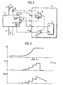
- Figure 1 shows a block diagram of the engine with a connected control unit
- Figure 2 shows a functional diagram to explain the operation.
- FIG. 1 shows an engine 1 of a motor vehicle, with an inlet area 2 and an outlet area 3 of the engine.
- a control unit 7 controls an injection unit 4 and an ignition unit 5 of the engine 1.
- a load sensor 8 detects the Load state of the engine 1 and outputs a load signal L to the control unit 7.
- a temperature sensor 9 detects the engine temperature T and a speed sensor 10 on the crankshaft of the engine 1 supplies a speed signal n to the control unit 7.
- engine 1 and control unit 7 are shown only very schematically in FIG. 1, since the person skilled in the art is familiar with the detection of the operating parameters of engine 1 and the design of injection unit 4 and ignition unit 5 and their control by control unit 7 .
- An engine control 6 is shown separately in the control unit 7.
- the engine control 6 calculates an injection time t E and an ignition angle a Z.
- Such a motor control system is known to the person skilled in the art as state of the art and is likewise not shown further in order to simplify the illustration.
- An ignition angle correction 11 calculates a correction ignition angle a ZK , which is subtracted from the ignition angle a Z of the engine control 6 in a summing point 12 in order to obtain the ignition angle a ZB valid for the acceleration, which is supplied as a control variable from the control unit 7 to the ignition unit 5.
- the ignition angle correction 11, the engine control 6 and the summing point 12 are largely implemented in the software in the control unit 7.
- the hardware of the control device 7 has receiving and driver circuits for various engine signals, such as the receiving circuits for the load signal L, temperature signal T and speed n and driver circuits for controlling the injection unit and the ignition unit 5, as well as the hardware structure a computer for processing the information contained in the signals.
- the structure of the control unit 7 in FIG. 1 thus represents the functional and not the circuit-related connection of the ignition angle adjustment according to the invention in this exemplary embodiment.
- FIG. 2 shows a load signal L over a time t, the load signal L having an increasing rate of change.
- the control unit 7 queries the state of the load signal L at time intervals dt.
- a signal dL is plotted below the load signal L in FIG. 2, which corresponds to the first time derivative of the sampled load signal L.
- the signal dL is therefore a measure of the rate of load change.
- Below the signal dL in FIG. 2 an associated correction ignition angle a Zk is plotted, as is calculated in the ignition angle correction 11 in FIG. 1.
- the signal dL is accepted and, after each positive edge, is regulated down approximately linearly in time, as is known as the state of the art.
- an ignition angle correction is carried out, although a previous ignition angle correction has not yet been completely reduced.
- the ignition angle correction is thus dynamic, and not only once depending on whether a fixed load threshold is exceeded.
Landscapes
- Engineering & Computer Science (AREA)
- Theoretical Computer Science (AREA)
- Signal Processing (AREA)
- Chemical & Material Sciences (AREA)
- Combustion & Propulsion (AREA)
- Mechanical Engineering (AREA)
- General Engineering & Computer Science (AREA)
- Electrical Control Of Ignition Timing (AREA)
- Auxiliary Drives, Propulsion Controls, And Safety Devices (AREA)
- Combined Controls Of Internal Combustion Engines (AREA)
Priority Applications (4)
| Application Number | Priority Date | Filing Date | Title |
|---|---|---|---|
| EP84108179A EP0167652B2 (fr) | 1984-07-12 | 1984-07-12 | Appareil de commande pour véhicule à moteur |
| DE8484108179T DE3478488D1 (en) | 1984-07-12 | 1984-07-12 | Control apparatus for a vehicle |
| JP60151467A JPH0735772B2 (ja) | 1984-07-12 | 1985-07-11 | 自動車用制御装置 |
| US06/896,315 US4697563A (en) | 1984-07-12 | 1986-08-12 | Method of controlling the operation of an automotive internal combustion engine |
Applications Claiming Priority (1)
| Application Number | Priority Date | Filing Date | Title |
|---|---|---|---|
| EP84108179A EP0167652B2 (fr) | 1984-07-12 | 1984-07-12 | Appareil de commande pour véhicule à moteur |
Publications (3)
| Publication Number | Publication Date |
|---|---|
| EP0167652A1 true EP0167652A1 (fr) | 1986-01-15 |
| EP0167652B1 EP0167652B1 (fr) | 1989-05-31 |
| EP0167652B2 EP0167652B2 (fr) | 1995-08-09 |
Family
ID=8192049
Family Applications (1)
| Application Number | Title | Priority Date | Filing Date |
|---|---|---|---|
| EP84108179A Expired - Lifetime EP0167652B2 (fr) | 1984-07-12 | 1984-07-12 | Appareil de commande pour véhicule à moteur |
Country Status (4)
| Country | Link |
|---|---|
| US (1) | US4697563A (fr) |
| EP (1) | EP0167652B2 (fr) |
| JP (1) | JPH0735772B2 (fr) |
| DE (1) | DE3478488D1 (fr) |
Cited By (5)
| Publication number | Priority date | Publication date | Assignee | Title |
|---|---|---|---|---|
| EP0245120A3 (en) * | 1986-05-09 | 1988-04-20 | Mitsubishi Denki Kabushiki Kaisha | Ignition timing control apparatus for an internal combustion engine |
| DE3832629A1 (de) * | 1988-09-26 | 1990-04-05 | Daimler Benz Ag | Verfahren zur dynamischen korrektur des zuendzeitpunktes einer brennkraftmaschine |
| WO1991015676A1 (fr) * | 1990-04-07 | 1991-10-17 | Robert Bosch Gmbh | Procede de reglage du moment d'allumage tenant compte des variations de charge |
| EP0803650A3 (fr) * | 1996-04-23 | 2000-01-12 | Toyota Jidosha Kabushiki Kaisha | Dispositif de commande de l'instant d'allumage pour un moteur à combustion interne |
| DE4220286C2 (de) * | 1992-06-20 | 2001-08-09 | Bosch Gmbh Robert | Verfahren zur Funktionsüberprüfung eines Stellelements in einem Fahrzeug |
Families Citing this family (10)
| Publication number | Priority date | Publication date | Assignee | Title |
|---|---|---|---|---|
| JPH0756247B2 (ja) * | 1986-02-14 | 1995-06-14 | 日産自動車株式会社 | 点火時期制御装置 |
| KR900002316B1 (ko) * | 1986-05-13 | 1990-04-11 | 미쓰비시전기 주식회사 | 점화시기 제어장치 |
| JPS63154862A (ja) * | 1986-12-17 | 1988-06-28 | Mitsubishi Electric Corp | 内燃機関の電子制御装置 |
| JPH089982B2 (ja) * | 1987-01-23 | 1996-01-31 | 株式会社日立製作所 | エンジンの点火時期制御装置 |
| US4745901A (en) * | 1987-02-24 | 1988-05-24 | General Motors Corporation | Control method for protecting an IC engine during extended heavy loading |
| JPH0751926B2 (ja) * | 1987-07-15 | 1995-06-05 | 株式会社ユニシアジェックス | 内燃機関の点火時期制御装置 |
| JPH01104973A (ja) * | 1987-10-15 | 1989-04-21 | Nissan Motor Co Ltd | 内燃機関の点火時期制御装置 |
| KR900016603A (ko) * | 1989-04-19 | 1990-11-14 | 시끼 모리야 | 내연기관의 제어 장치 |
| US5497745A (en) * | 1995-02-24 | 1996-03-12 | Ford Motor Company | Engine control for enhanced catalyst warm up while maintaining manifold vacuum |
| WO1999058849A1 (fr) * | 1998-05-12 | 1999-11-18 | Robert Bosch Gmbh | Procede de commande d'allumage |
Citations (3)
| Publication number | Priority date | Publication date | Assignee | Title |
|---|---|---|---|---|
| GB2069603A (en) * | 1980-02-15 | 1981-08-26 | Nissan Motor | Spark timing control system for internal combustion engine |
| DE3112023A1 (de) * | 1980-03-26 | 1982-02-18 | Nippondenso Co., Ltd., Kariya, Aichi | Verfahren und vorrichtung zum steuern des erregungsintervalls der zuendspule einer brennkraftmaschine |
| US4377996A (en) * | 1980-02-12 | 1983-03-29 | Nissan Motor Co., Ltd. | Ignition timing control method and system |
Family Cites Families (13)
| Publication number | Priority date | Publication date | Assignee | Title |
|---|---|---|---|---|
| JPS5335221B2 (fr) * | 1973-06-30 | 1978-09-26 | ||
| JPS5535165A (en) * | 1978-09-06 | 1980-03-12 | Hitachi Ltd | Controlling acceleration of automobile engine |
| JPS55137361A (en) * | 1979-04-16 | 1980-10-27 | Nissan Motor Co Ltd | Ignition timing controller |
| JPS5945832B2 (ja) * | 1980-09-29 | 1984-11-08 | 日産自動車株式会社 | 点火時期制御装置 |
| JPS5768544A (en) * | 1980-10-17 | 1982-04-26 | Nippon Denso Co Ltd | Controlling method for internal combustion engine |
| JPS6030474Y2 (ja) * | 1980-11-26 | 1985-09-12 | 日産自動車株式会社 | 内燃機関のノツキング回避装置 |
| JPS57195867A (en) * | 1981-05-27 | 1982-12-01 | Nippon Denso Co Ltd | Firing timing controller for internal combustion engine |
| JPS5813160A (ja) * | 1981-07-17 | 1983-01-25 | Nippon Denso Co Ltd | 点火進角制御装置 |
| JPS58143166A (ja) * | 1982-02-17 | 1983-08-25 | Hitachi Ltd | 電子制御点火装置 |
| JPS6026171A (ja) * | 1983-07-22 | 1985-02-09 | Mazda Motor Corp | エンジンの点火時期制御装置 |
| JPS6032955A (ja) * | 1983-08-01 | 1985-02-20 | Toyota Motor Corp | 燃料噴射制御方法 |
| JPS6073056A (ja) * | 1983-09-29 | 1985-04-25 | Toyota Motor Corp | 点火時期制御装置 |
| US4509481A (en) * | 1984-01-25 | 1985-04-09 | Nissan Motor Co., Ltd. | Internal combustion engine with cooling system |
-
1984
- 1984-07-12 EP EP84108179A patent/EP0167652B2/fr not_active Expired - Lifetime
- 1984-07-12 DE DE8484108179T patent/DE3478488D1/de not_active Expired
-
1985
- 1985-07-11 JP JP60151467A patent/JPH0735772B2/ja not_active Expired - Fee Related
-
1986
- 1986-08-12 US US06/896,315 patent/US4697563A/en not_active Expired - Lifetime
Patent Citations (3)
| Publication number | Priority date | Publication date | Assignee | Title |
|---|---|---|---|---|
| US4377996A (en) * | 1980-02-12 | 1983-03-29 | Nissan Motor Co., Ltd. | Ignition timing control method and system |
| GB2069603A (en) * | 1980-02-15 | 1981-08-26 | Nissan Motor | Spark timing control system for internal combustion engine |
| DE3112023A1 (de) * | 1980-03-26 | 1982-02-18 | Nippondenso Co., Ltd., Kariya, Aichi | Verfahren und vorrichtung zum steuern des erregungsintervalls der zuendspule einer brennkraftmaschine |
Cited By (5)
| Publication number | Priority date | Publication date | Assignee | Title |
|---|---|---|---|---|
| EP0245120A3 (en) * | 1986-05-09 | 1988-04-20 | Mitsubishi Denki Kabushiki Kaisha | Ignition timing control apparatus for an internal combustion engine |
| DE3832629A1 (de) * | 1988-09-26 | 1990-04-05 | Daimler Benz Ag | Verfahren zur dynamischen korrektur des zuendzeitpunktes einer brennkraftmaschine |
| WO1991015676A1 (fr) * | 1990-04-07 | 1991-10-17 | Robert Bosch Gmbh | Procede de reglage du moment d'allumage tenant compte des variations de charge |
| DE4220286C2 (de) * | 1992-06-20 | 2001-08-09 | Bosch Gmbh Robert | Verfahren zur Funktionsüberprüfung eines Stellelements in einem Fahrzeug |
| EP0803650A3 (fr) * | 1996-04-23 | 2000-01-12 | Toyota Jidosha Kabushiki Kaisha | Dispositif de commande de l'instant d'allumage pour un moteur à combustion interne |
Also Published As
| Publication number | Publication date |
|---|---|
| EP0167652B2 (fr) | 1995-08-09 |
| DE3478488D1 (en) | 1989-07-06 |
| JPS6146467A (ja) | 1986-03-06 |
| JPH0735772B2 (ja) | 1995-04-19 |
| EP0167652B1 (fr) | 1989-05-31 |
| US4697563A (en) | 1987-10-06 |
Similar Documents
| Publication | Publication Date | Title |
|---|---|---|
| DE3717368C2 (de) | Vorrichtung zur Dämpfung von Ruckelschwingungen von Kraftfahrzeugen | |
| EP0167652B2 (fr) | Appareil de commande pour véhicule à moteur | |
| EP0109545B1 (fr) | Dispositif pour amortir les irrégularités de marche d'un moteur à combustion interne dans un véhicule | |
| DE69333932T2 (de) | Zündungsteuersystem und Methode für eine Brennkraftmaschine | |
| DE2949151C2 (de) | Vorrichtung zum Regeln der Leerlaufdrehzahl für einen Verbrennungsmotor in Abhängigkeit von den Betriebsparametern | |
| DE3504197A1 (de) | Verfahren und vorrichtung zur regelung der ansaugluftmenge einer brennkraftmaschine in abhaengigkeit von der ausgangsdrehzahl | |
| DE69107585T2 (de) | Motorausgangsmoment-Steuerungssystem. | |
| DE3036180A1 (de) | Zuendzeitpunktregler fuer brennkraftmotoren | |
| DE3105334A1 (de) | System zum steuern des zuendzeitpunktes bei einer brennkraftmaschine | |
| DE19754614A1 (de) | Vorrichtung zur Steuerung eines Unterdrucks in einer Brennkraftmaschine | |
| DE2841268A1 (de) | Einrichtung zum erhoehen der kraftstoffzufuhr bei brennkraftmaschinen im beschleunigungsfalle | |
| DE2736306A1 (de) | Kraftstoffversorgungsanlage fuer eine brennkraftmaschine mit fremdzuendung | |
| DE3805823C3 (de) | Elektronische Steuerung für einen Verbrennungsmotor | |
| DE4022704C2 (de) | System zur Steuerung des Zündzeitpunkts einer Brennkraftmaschine | |
| DE19736522A1 (de) | Verfahren zur Steuerung der Abgasrückführung bei einer Brennkraftmaschine | |
| EP0435976B1 (fr) | Procede pour la commande du debit de carburant de moteurs a combustion interne | |
| DE3629197C2 (fr) | ||
| DE3036199A1 (de) | Verfahren zum betreiben eines verbrennungsmotors mit kraftstoffeinspritzung an einer einzigen einspritzstelle und einrichtung zur durchfuehrung eines solchen verfahrens | |
| DE4121561C2 (de) | Zündsteuerungssystem für einen Verbrennungsmotor mit Kraftstoffeinspritzung | |
| DE3613828A1 (de) | Ansauggeraeuschdaempfer, insbesondere fuer brennkraftmaschinen | |
| EP0128523B1 (fr) | Procédé d'utilisation de machine à combustion | |
| EP0415048B1 (fr) | Procédé de régulation d'un ensemble moteur/transmission | |
| DE3744331C2 (de) | System zur Steuerung der Kraftstoffmenge einer zum Antrieb eines Fahrzeugs dienenden Brennkraftmaschine | |
| DE19700104B4 (de) | Steuervorrichtung für Mehrzylinder-Direkteinpritzmotor | |
| DE69101509T2 (de) | Steuergerät zur Steuerung des Luft-Kraftstoff-Gemisches für eine Brennkraftmaschine. |
Legal Events
| Date | Code | Title | Description |
|---|---|---|---|
| PUAI | Public reference made under article 153(3) epc to a published international application that has entered the european phase |
Free format text: ORIGINAL CODE: 0009012 |
|
| 17P | Request for examination filed |
Effective date: 19840712 |
|
| AK | Designated contracting states |
Designated state(s): DE FR GB IT SE |
|
| 17Q | First examination report despatched |
Effective date: 19871112 |
|
| GRAA | (expected) grant |
Free format text: ORIGINAL CODE: 0009210 |
|
| AK | Designated contracting states |
Kind code of ref document: B1 Designated state(s): DE FR GB IT SE |
|
| GBT | Gb: translation of ep patent filed (gb section 77(6)(a)/1977) | ||
| REF | Corresponds to: |
Ref document number: 3478488 Country of ref document: DE Date of ref document: 19890706 |
|
| ET | Fr: translation filed | ||
| ITF | It: translation for a ep patent filed | ||
| PLBI | Opposition filed |
Free format text: ORIGINAL CODE: 0009260 |
|
| 26 | Opposition filed |
Opponent name: SIEMENS AKTIENGESELLSCHAFT, BERLIN UND MUENCHEN Effective date: 19900213 |
|
| ITTA | It: last paid annual fee | ||
| RAP4 | Party data changed (patent owner data changed or rights of a patent transferred) |
Owner name: ROBERT BOSCH GMBH |
|
| EAL | Se: european patent in force in sweden |
Ref document number: 84108179.7 |
|
| PUAH | Patent maintained in amended form |
Free format text: ORIGINAL CODE: 0009272 |
|
| STAA | Information on the status of an ep patent application or granted ep patent |
Free format text: STATUS: PATENT MAINTAINED AS AMENDED |
|
| 27A | Patent maintained in amended form |
Effective date: 19950809 |
|
| AK | Designated contracting states |
Kind code of ref document: B2 Designated state(s): DE FR GB IT SE |
|
| ET3 | Fr: translation filed ** decision concerning opposition | ||
| GBTA | Gb: translation of amended ep patent filed (gb section 77(6)(b)/1977) |
Effective date: 19950809 |
|
| ITF | It: translation for a ep patent filed | ||
| APAC | Appeal dossier modified |
Free format text: ORIGINAL CODE: EPIDOS NOAPO |
|
| APAC | Appeal dossier modified |
Free format text: ORIGINAL CODE: EPIDOS NOAPO |
|
| REG | Reference to a national code |
Ref country code: GB Ref legal event code: IF02 |
|
| PGFP | Annual fee paid to national office [announced via postgrant information from national office to epo] |
Ref country code: GB Payment date: 20020626 Year of fee payment: 19 |
|
| PGFP | Annual fee paid to national office [announced via postgrant information from national office to epo] |
Ref country code: FR Payment date: 20020723 Year of fee payment: 19 |
|
| PGFP | Annual fee paid to national office [announced via postgrant information from national office to epo] |
Ref country code: SE Payment date: 20020726 Year of fee payment: 19 |
|
| PGFP | Annual fee paid to national office [announced via postgrant information from national office to epo] |
Ref country code: DE Payment date: 20020826 Year of fee payment: 19 |
|
| PG25 | Lapsed in a contracting state [announced via postgrant information from national office to epo] |
Ref country code: GB Free format text: LAPSE BECAUSE OF NON-PAYMENT OF DUE FEES Effective date: 20030712 |
|
| PG25 | Lapsed in a contracting state [announced via postgrant information from national office to epo] |
Ref country code: SE Free format text: LAPSE BECAUSE OF NON-PAYMENT OF DUE FEES Effective date: 20030713 |
|
| PG25 | Lapsed in a contracting state [announced via postgrant information from national office to epo] |
Ref country code: DE Free format text: LAPSE BECAUSE OF NON-PAYMENT OF DUE FEES Effective date: 20040203 |
|
| EUG | Se: european patent has lapsed | ||
| GBPC | Gb: european patent ceased through non-payment of renewal fee |
Effective date: 20030712 |
|
| PG25 | Lapsed in a contracting state [announced via postgrant information from national office to epo] |
Ref country code: FR Free format text: LAPSE BECAUSE OF NON-PAYMENT OF DUE FEES Effective date: 20040331 |
|
| REG | Reference to a national code |
Ref country code: FR Ref legal event code: ST |
|
| APAH | Appeal reference modified |
Free format text: ORIGINAL CODE: EPIDOSCREFNO |