EP0167876B1 - Thermomètre électrique - Google Patents
Thermomètre électrique Download PDFInfo
- Publication number
- EP0167876B1 EP0167876B1 EP85107339A EP85107339A EP0167876B1 EP 0167876 B1 EP0167876 B1 EP 0167876B1 EP 85107339 A EP85107339 A EP 85107339A EP 85107339 A EP85107339 A EP 85107339A EP 0167876 B1 EP0167876 B1 EP 0167876B1
- Authority
- EP
- European Patent Office
- Prior art keywords
- temperature
- code
- measuring
- processing unit
- electronic thermometer
- Prior art date
- Legal status (The legal status is an assumption and is not a legal conclusion. Google has not performed a legal analysis and makes no representation as to the accuracy of the status listed.)
- Expired
Links
- 238000001514 detection method Methods 0.000 claims description 7
- 238000009413 insulation Methods 0.000 claims description 7
- 230000002093 peripheral effect Effects 0.000 claims 1
- 230000000712 assembly Effects 0.000 abstract description 3
- 238000000429 assembly Methods 0.000 abstract description 3
- 238000009529 body temperature measurement Methods 0.000 description 4
- 238000000034 method Methods 0.000 description 4
- 238000010586 diagram Methods 0.000 description 2
- 239000000919 ceramic Substances 0.000 description 1
- 239000004020 conductor Substances 0.000 description 1
- 230000003247 decreasing effect Effects 0.000 description 1
- 230000006870 function Effects 0.000 description 1
- 238000009434 installation Methods 0.000 description 1
- 230000003287 optical effect Effects 0.000 description 1
Images

Classifications
-
- G—PHYSICS
- G01—MEASURING; TESTING
- G01K—MEASURING TEMPERATURE; MEASURING QUANTITY OF HEAT; THERMALLY-SENSITIVE ELEMENTS NOT OTHERWISE PROVIDED FOR
- G01K13/00—Thermometers specially adapted for specific purposes
- G01K13/20—Clinical contact thermometers for use with humans or animals
-
- G—PHYSICS
- G01—MEASURING; TESTING
- G01K—MEASURING TEMPERATURE; MEASURING QUANTITY OF HEAT; THERMALLY-SENSITIVE ELEMENTS NOT OTHERWISE PROVIDED FOR
- G01K1/00—Details of thermometers not specially adapted for particular types of thermometer
- G01K1/02—Means for indicating or recording specially adapted for thermometers
Definitions
- the present invention generally relates to an electronic thermometer_ system. More particularly, the invention concerns as electronic thermometer system which is so arranged as to correct measured temperature in consideration of temperature characteristic of a temperature sensor element incorporated in a temperature sensing unit or assembly which is adapted to be disconnectably coupled to a main body of the thermometer so as to be exchangeable with another temperature sensing unit or assembly.
- thermometer which comprises a temperature sensing unit or assembly incorporating a thermosensitive element or temperature sensor element and a measuring and processing unit for measuring or determining the temperature of an object to be measured such as human body on the basis of an electric signal available at the output of the temperature sensor element, wherein the latter is disconnectably combined with the measuring and processing unit so that the temperature sensing unit or assembly can be exchanged with another sensing assembly.
- correction circuits are provided in the temperature sensing assembly and the measuring/processing unit, respectively. Owing to remarkable advance in the electronic technology in the recent years, the temperature sensing assembly can be manufactured at such very low cost that it may be discarded after use, a disposable thermometer, so to say, unless correction or compensating circuit is required.
- thermometer arrangement An example of a prior art disposable thermometer arrangement is disclosed in US-A-4116064.
- disconnectable or separatable temperature sensing assembly of this type tends to be used on the disposable basis in hospitals or the like where a large amount of temperature measuring and processing task is to be dealt with.
- thermometer including the correction or compensation circuits in the temperature sensing assembly and the measuring processing unit, respectively, is disadvantageous in that the circuit configuration such as that of the detection circuit is much complicated, giving rise to a problem that the thermometer is too expensive to be disposable.
- thermometer A digital correction system for a thermometer is known from e.g. US ⁇ A ⁇ 4 198 676.
- thermometer system which is capable of performing correction on the measured temperature in accordance with the temperature characteristic or the like of the temperature sensor element as employed.
- Another object of the present invention is to provide the electronic thermometer system of the aforementioned type in which no correction circuit is required to be installed in the temperature sensing assembly.
- Still another object of the invention is provide the electronic thermometer system of the aforementioned type in which the temperature sensing assembly can be manufactured so inexpensively as to be disposable.
- a further object of the invention is to provide the electronic thermometer system of the aforementioned type which is capable of performing temperature measurement at a high accuracy with an enhanced reliability.
- thermometer system according to the present invention is defined in claim 1.
- the measured temperature i.e. temperature determined by the measuring and processing unit
- the mutually exchangeable temperature sensing assemblies can be realized at such low cost as to be disposable, while assuring the temperature measurement with an improved accuracy.
- a reference numeral 1 generally denotes a temperature sensing assembly realized in the form of a tongue-like sheet.
- the temperature sensing assembly 1 includes a temperature sensor element 2, lead wires 3 for taking out an electric signal from the sensor element 2 and lead terminals 8 for external connection.
- the temperature sensing assembly 1 may be constituted by bonding together a pair of electrically insulation films, both or one of which has an inner surface printed with electric conductor patterns.
- the temperature sensor element 2 such as a thermistor is enclosed within the laminated insulation films which are insulatingly sealed off at least along the periphery. Referring to Fig.
- the sheet-like temperature sensing assembly 1 is provided with perforations 5a, 7b formed in a region located on the side of the lead terminals 8 and representing encoded temperature characteristic of the temperature sensor element 2 as employed.
- a reference numeral 4 generally denotes a main body of the electronic thermometer.
- the temperature sensing assembly 1 is held by the main body 4 in a sandwiched state in the manner illustrated in Fig. 2.
- the main body 4 is composed of a pair of insulation members 4a and 4b, wherein the insulation member 4a is provided with electrically conductive rubber studs at predetermined locations, while the insulation member 4b is provided with electrically conductive patterns, as will be described below.
- a reference numeral 5 generally designates a reader unit 5 which includes the electrically conductive rubber layers 5a, 6a and 7a and the electrically conductive patterns 5c, 5d, 6c, 6d and 7c, 7d which constitute a code reader circuit in cooperation with the electrically conductive rubber studs 5a, 6a and 7a. It is to be understood that the components constituting the reader unit 5 may be increased or decreased in number; as occasions require.
- a reference numeral 9 denotes a connector or switch portion which includes an electrically conductive pattern or pad 10 and a projecting stud 11 which serves to bring the conductive pattern 10 in electrical contract with the lead terminals 8 in the state where the temperature sensing assembly 1 is held by the main body 4 in the sandwiched manner.
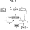
- Fig. 4 shows in a block diagram a general arrangement of an electrical system of the electronic thermometer according to an exemplary embodiment of the invention.
- reference numeral 12 denotes a detection circuit for detecting the output signal derived from the temperature sensing element 2 as an analogue quantity.
- a numeral 13 denotes an analogue-to-digital converter which functions to convert the analogue signal output from the detection circuit 12 into a corresponding digital signal.
- a reference numeral 14 denotes the aforementioned code reader circuit which serves to output the code (encoded by the perforations formed in the temperature sensing assembly 1) read by the reader unit 5 as a digital data signal.
- a central processing unit or CPU 15 is supplied with the digital signal from the A/D converter 13 and the digital signal output from the code reader circuit 14.
- a memory 16 is connected to the CPU 15 for storing therein a data table referred to upon arithmetic determination of the temperature by the CPU 15 on the basis of the signal originating in the temperature sensor element 2.
- a reference numeral 17 denotes a display unit to which data representative of the temperature determined arithmetically by the CPU 15 is supplied to be displayed.
- the temperature sensing assembly 1 is held by the main body 4 in the sandwiched manner.
- the electrically conductive rubber studs 5a and 7a are inserted in the perforations 5b and 7b, respectively, formed in the temperature sensing assembly 2 and indicative of the encoded temperature characteristic or the like of the temperature sensor element 2.
- the electrically conductive pattern 5c is connected to the pattern 5d with the patterns 7c and 7d being connected to each other, whereby corresponding closed circuits are formed.
- the electrically conductive rubber stud 6a located in opposition to the region where no perforation is formed is resiliently compressed, as is. shown in Fig. 2.
- the code reader circuit 15 supplies to the CPU 15 a digital data signal (e.g. "0101") corresponding to the aforenoted closed circuit states and the open circuit.
- the output signal of the temperature sensor element 2 is detected by the detection circuit 12.
- the analogue signal outputted from the detection circuit 12 is converted into the digital signal through the A/D converter 13, the digital signal in turn being supplied to the input of the CPU 15.
- the CPU 15 supplied with the data detected by the temperature sensor element 2 as well as data representative of the encoded temperature characteristic or the like of the temperature sensor element 2 arithmetically determines the temperature on the basis of these data with the aid of temperature data read out from the table stored in the memory 16.
- the temperature determined arithmetically is subsequently corrected by utilizing data for correction also stored in the memory 16 and read out in accordance with the encoded data of temperature characteristic or the like. More specifically, in case a thermistor or the like is employed as the temperature sensor element, by way of example, deviation of the resistance of such element from a standard temperature-resistance curve (i.e.
- temperature characteristic coding method as well as the code reading method may be practiced in other ways than the illustrated one without departing from the scope of the invention.
- a magnetic code recording and reading system a bar code recording method combined with an optical reader device, a perforation code array in combination with photoelectrical switch type code reader, a color code recording and reading method, or recording and reading of marks of different sizes and others.
- thermosensitive diode thermosensitive diode
- ceramic element the amount for correction corresponding to these different sensor elements can be encoded and recorded in the temperature sensing assemblies incorporating these sensor elements, respectively, wherein the code may be used to address the location of the memory where the associated data for correction is stored.
Landscapes
- Physics & Mathematics (AREA)
- General Physics & Mathematics (AREA)
- Measuring Temperature Or Quantity Of Heat (AREA)
- Glass Compositions (AREA)
- Organic Insulating Materials (AREA)
- Paints Or Removers (AREA)
- Carbon And Carbon Compounds (AREA)
- Measuring And Recording Apparatus For Diagnosis (AREA)
Claims (12)
Priority Applications (1)
| Application Number | Priority Date | Filing Date | Title |
|---|---|---|---|
| AT85107339T ATE49052T1 (de) | 1984-06-13 | 1985-06-13 | Elektrisches thermometer. |
Applications Claiming Priority (2)
| Application Number | Priority Date | Filing Date | Title |
|---|---|---|---|
| JP59121032A JPH076849B2 (ja) | 1984-06-13 | 1984-06-13 | 電子温度計 |
| JP121032/84 | 1984-06-13 |
Publications (3)
| Publication Number | Publication Date |
|---|---|
| EP0167876A2 EP0167876A2 (fr) | 1986-01-15 |
| EP0167876A3 EP0167876A3 (en) | 1987-04-29 |
| EP0167876B1 true EP0167876B1 (fr) | 1989-12-27 |
Family
ID=14801128
Family Applications (1)
| Application Number | Title | Priority Date | Filing Date |
|---|---|---|---|
| EP85107339A Expired EP0167876B1 (fr) | 1984-06-13 | 1985-06-13 | Thermomètre électrique |
Country Status (5)
| Country | Link |
|---|---|
| US (1) | US4958936A (fr) |
| EP (1) | EP0167876B1 (fr) |
| JP (1) | JPH076849B2 (fr) |
| AT (1) | ATE49052T1 (fr) |
| DE (1) | DE3575019D1 (fr) |
Families Citing this family (16)
| Publication number | Priority date | Publication date | Assignee | Title |
|---|---|---|---|---|
| EP0213239A1 (fr) * | 1985-07-29 | 1987-03-11 | Milton Schonberger | Thermomètre jetable et technique pour son étalonnage |
| EP0193950A3 (fr) * | 1985-03-07 | 1988-06-15 | Spacelabs, Inc. | Méthode et appareil pour la mesure automatique de températures |
| JPS62197033U (fr) * | 1986-06-05 | 1987-12-15 | ||
| GB2262344B (en) * | 1991-12-13 | 1994-08-31 | Zeal Holdings Limited | A temperature measuring system |
| US5706812A (en) * | 1995-11-24 | 1998-01-13 | Diagnostic Instruments, Inc. | Stereotactic MRI breast biopsy coil and method for use |
| US5857777A (en) * | 1996-09-25 | 1999-01-12 | Claud S. Gordon Company | Smart temperature sensing device |
| US20030002562A1 (en) * | 2001-06-27 | 2003-01-02 | Yerlikaya Y. Denis | Temperature probe adapter |
| US20040071182A1 (en) * | 2002-10-11 | 2004-04-15 | Welch Allyn, Inc. | Thermometry probe calibration method |
| US6971790B2 (en) * | 2002-10-11 | 2005-12-06 | Welch Allyn, Inc. | Thermometry probe calibration method |
| US20040076220A1 (en) * | 2002-10-21 | 2004-04-22 | Tseng Daniel C.M. | Method for identifying the classification of temperature detection components of electronic thermometers |
| ES2385346T3 (es) * | 2003-12-14 | 2012-07-23 | Actherm Inc. | Termómetro electrónico clínico con sonda desmontable |
| JP2005323417A (ja) * | 2004-05-06 | 2005-11-17 | Mitsubishi Electric Corp | 電力変換装置 |
| US7447607B2 (en) * | 2004-08-31 | 2008-11-04 | Watow Electric Manufacturing | System and method of compensation for device mounting and thermal transfer error |
| US8794829B2 (en) | 2009-12-31 | 2014-08-05 | Welch Allyn, Inc. | Temperature-measurement probe |
| JP6565014B1 (ja) * | 2018-10-04 | 2019-08-28 | 株式会社エム・システム技研 | 温度計測装置、及び、体温計 |
| JP7341456B2 (ja) * | 2019-07-22 | 2023-09-11 | 株式会社エム・システム技研 | 温度計測装置、及び、体温計 |
Family Cites Families (23)
| Publication number | Priority date | Publication date | Assignee | Title |
|---|---|---|---|---|
| US3200240A (en) * | 1960-12-07 | 1965-08-10 | Rca Corp | Perforated record member sensing apparatus |
| US3336448A (en) * | 1965-09-02 | 1967-08-15 | Electronix Ten Inc | Non-sparking switching apparatus |
| US3493730A (en) * | 1966-09-14 | 1970-02-03 | Western Electric Co | Data input card |
| GB1349360A (en) * | 1971-04-08 | 1974-04-03 | Sealectro Corp | Punched card readers |
| US3733862A (en) * | 1971-06-22 | 1973-05-22 | Mears E | Combined mechanical and photoelectric lock |
| US4022063A (en) * | 1974-10-15 | 1977-05-10 | Rwb Labs | Electromechanical digital thermometer |
| DE2527739C3 (de) * | 1975-06-21 | 1978-08-31 | W.C. Heraeus Gmbh, 6450 Hanau | Verfahren zur Herstellung eines elektrischen Meßwiderstandes für ein Widerstandsthermometer |
| US4095467A (en) * | 1975-07-09 | 1978-06-20 | Ipco Hospital Supply Corporation | Disposable tape cord thermometer |
| US4317367A (en) * | 1977-03-18 | 1982-03-02 | Milton Schonberger | Fever thermometer, or the like sensor |
| JPS53137191A (en) * | 1977-05-06 | 1978-11-30 | Omron Tateisi Electronics Co | Electronic clinical thermometer |
| US4161880A (en) * | 1978-01-05 | 1979-07-24 | Electromedics, Inc. | Linearized digital thermometer |
| JPS5520514A (en) * | 1978-07-28 | 1980-02-14 | Toshiba Corp | Electronic thermostat |
| US4198676A (en) * | 1978-12-20 | 1980-04-15 | Livezey Robert L Jr | General purpose electronic thermometer having selective data recovery, data conversion, and data derivation capabilities |
| US4276536A (en) * | 1979-09-04 | 1981-06-30 | Scully Electronic Systems, Inc. | Self-heating thermistor probe for low temperature applications |
| US4304991A (en) * | 1979-09-26 | 1981-12-08 | Weber Harold J | Indicia sensor apparatus |
| EP0079086B1 (fr) * | 1981-11-10 | 1987-07-01 | Sentron v.o.f. | Capteur à cathéter avec une unité de mémoire |
| JPS58200118A (ja) * | 1982-05-18 | 1983-11-21 | Seiko Instr & Electronics Ltd | 電子体温計 |
| JPS5940113A (ja) * | 1982-08-30 | 1984-03-05 | Hino Motors Ltd | センサ−の誤差補償方法 |
| US4493564A (en) * | 1982-09-27 | 1985-01-15 | Saul Epstein | Clinical instrument for measuring pulse rate and body temperature |
| US4537516A (en) * | 1982-09-27 | 1985-08-27 | Saul Epstein | Electronic thermometer |
| US4531842A (en) * | 1983-10-31 | 1985-07-30 | Milton Schonberger | Disposable thermometer probe and rating technique therefor |
| JPS60243506A (ja) * | 1984-05-18 | 1985-12-03 | Terumo Corp | 計測用プロ−ブ |
| JPS60243510A (ja) * | 1984-05-18 | 1985-12-03 | Terumo Corp | 測定情報処理装置 |
-
1984
- 1984-06-13 JP JP59121032A patent/JPH076849B2/ja not_active Expired - Lifetime
-
1985
- 1985-06-13 EP EP85107339A patent/EP0167876B1/fr not_active Expired
- 1985-06-13 AT AT85107339T patent/ATE49052T1/de not_active IP Right Cessation
- 1985-06-13 DE DE8585107339T patent/DE3575019D1/de not_active Expired - Fee Related
-
1987
- 1987-01-27 US US07/008,078 patent/US4958936A/en not_active Expired - Fee Related
Also Published As
| Publication number | Publication date |
|---|---|
| JPH076849B2 (ja) | 1995-01-30 |
| DE3575019D1 (de) | 1990-02-01 |
| US4958936A (en) | 1990-09-25 |
| EP0167876A2 (fr) | 1986-01-15 |
| JPS61727A (ja) | 1986-01-06 |
| EP0167876A3 (en) | 1987-04-29 |
| ATE49052T1 (de) | 1990-01-15 |
Similar Documents
| Publication | Publication Date | Title |
|---|---|---|
| US4958936A (en) | Electric thermometer | |
| US10578651B2 (en) | Current sensing resistor, current sensing device, and method for producing the same | |
| EP0361456A2 (fr) | Détecteur magnétique | |
| US4649364A (en) | Bifunctional environment sensor | |
| US4567763A (en) | Passive encoder for range knobs | |
| JPS5849812B2 (ja) | 温度センサ−の製造方法 | |
| US5761952A (en) | Electrochemical gas sensor | |
| US6353325B1 (en) | Apparatus for examining posture of an electronic part | |
| US5045710A (en) | Coplanarity inspection machine | |
| EP0430651A1 (fr) | Détecteur de niveau | |
| JPS61144521A (ja) | 温度センサ | |
| JP2000346601A (ja) | 環境補正長さ計測器及びマイクロメータ用記録媒体 | |
| US6429670B2 (en) | Method of examining posture of an electronic part | |
| JP3361020B2 (ja) | 熱電対温度測定装置 | |
| JPS60243510A (ja) | 測定情報処理装置 | |
| EP0594215A1 (fr) | Appareil de contrôle d'entraînement pour micro-capteur | |
| JPH0755833Y2 (ja) | 温度補償素子内蔵コネクタ | |
| US3625059A (en) | Remote cryogenic temperature indicating system | |
| JP4540774B2 (ja) | 端子台 | |
| JP2550839Y2 (ja) | 磁気センサ | |
| JPS62200236A (ja) | 基準点補償装置 | |
| JPS63120233A (ja) | 表面温センサ | |
| JPS61112953A (ja) | 外部雰囲気検知装置 | |
| JPS6177731A (ja) | 電子温度計 | |
| US20100323553A1 (en) | Temperature Compensation Element for a Connection Unit |
Legal Events
| Date | Code | Title | Description |
|---|---|---|---|
| PUAI | Public reference made under article 153(3) epc to a published international application that has entered the european phase |
Free format text: ORIGINAL CODE: 0009012 |
|
| AK | Designated contracting states |
Designated state(s): AT BE CH DE FR GB IT LI LU NL SE |
|
| PUAL | Search report despatched |
Free format text: ORIGINAL CODE: 0009013 |
|
| AK | Designated contracting states |
Kind code of ref document: A3 Designated state(s): AT BE CH DE FR GB IT LI LU NL SE |
|
| 17P | Request for examination filed |
Effective date: 19870811 |
|
| 17Q | First examination report despatched |
Effective date: 19890117 |
|
| GRAA | (expected) grant |
Free format text: ORIGINAL CODE: 0009210 |
|
| AK | Designated contracting states |
Kind code of ref document: B1 Designated state(s): AT BE CH DE FR GB IT LI LU NL SE |
|
| PG25 | Lapsed in a contracting state [announced via postgrant information from national office to epo] |
Ref country code: SE Effective date: 19891227 Ref country code: NL Effective date: 19891227 Ref country code: LI Effective date: 19891227 Ref country code: CH Effective date: 19891227 Ref country code: BE Effective date: 19891227 Ref country code: AT Effective date: 19891227 |
|
| REF | Corresponds to: |
Ref document number: 49052 Country of ref document: AT Date of ref document: 19900115 Kind code of ref document: T |
|
| REF | Corresponds to: |
Ref document number: 3575019 Country of ref document: DE Date of ref document: 19900201 |
|
| ET | Fr: translation filed | ||
| ITF | It: translation for a ep patent filed | ||
| REG | Reference to a national code |
Ref country code: CH Ref legal event code: PL |
|
| PGFP | Annual fee paid to national office [announced via postgrant information from national office to epo] |
Ref country code: GB Payment date: 19900511 Year of fee payment: 6 |
|
| NLV1 | Nl: lapsed or annulled due to failure to fulfill the requirements of art. 29p and 29m of the patents act | ||
| PGFP | Annual fee paid to national office [announced via postgrant information from national office to epo] |
Ref country code: FR Payment date: 19900608 Year of fee payment: 6 |
|
| PGFP | Annual fee paid to national office [announced via postgrant information from national office to epo] |
Ref country code: DE Payment date: 19900629 Year of fee payment: 6 |
|
| PG25 | Lapsed in a contracting state [announced via postgrant information from national office to epo] |
Ref country code: LU Free format text: LAPSE BECAUSE OF NON-PAYMENT OF DUE FEES Effective date: 19900630 |
|
| PLBE | No opposition filed within time limit |
Free format text: ORIGINAL CODE: 0009261 |
|
| STAA | Information on the status of an ep patent application or granted ep patent |
Free format text: STATUS: NO OPPOSITION FILED WITHIN TIME LIMIT |
|
| 26N | No opposition filed | ||
| PG25 | Lapsed in a contracting state [announced via postgrant information from national office to epo] |
Ref country code: GB Effective date: 19910613 |
|
| GBPC | Gb: european patent ceased through non-payment of renewal fee | ||
| PG25 | Lapsed in a contracting state [announced via postgrant information from national office to epo] |
Ref country code: FR Effective date: 19920228 |
|
| PG25 | Lapsed in a contracting state [announced via postgrant information from national office to epo] |
Ref country code: DE Effective date: 19920401 |
|
| REG | Reference to a national code |
Ref country code: FR Ref legal event code: ST |