EP0167917A1 - Dispositif de collage de rubans, notamment de rubans de papier à cigarettes - Google Patents
Dispositif de collage de rubans, notamment de rubans de papier à cigarettes Download PDFInfo
- Publication number
- EP0167917A1 EP0167917A1 EP85107824A EP85107824A EP0167917A1 EP 0167917 A1 EP0167917 A1 EP 0167917A1 EP 85107824 A EP85107824 A EP 85107824A EP 85107824 A EP85107824 A EP 85107824A EP 0167917 A1 EP0167917 A1 EP 0167917A1
- Authority
- EP
- European Patent Office
- Prior art keywords
- web
- splicing
- webs
- roller
- bobbin
- Prior art date
- Legal status (The legal status is an assumption and is not a legal conclusion. Google has not performed a legal analysis and makes no representation as to the accuracy of the status listed.)
- Granted
Links
- 235000019504 cigarettes Nutrition 0.000 title claims abstract description 7
- 238000011144 upstream manufacturing Methods 0.000 claims description 6
- 230000009471 action Effects 0.000 claims description 5
- 239000000853 adhesive Substances 0.000 claims description 4
- 230000001070 adhesive effect Effects 0.000 claims description 4
- 230000005540 biological transmission Effects 0.000 claims 2
- 230000000694 effects Effects 0.000 description 2
- 239000000463 material Substances 0.000 description 2
- 230000004888 barrier function Effects 0.000 description 1
- 238000010276 construction Methods 0.000 description 1
- 230000002950 deficient Effects 0.000 description 1
- 230000000779 depleting effect Effects 0.000 description 1
- 230000002093 peripheral effect Effects 0.000 description 1
- 230000004044 response Effects 0.000 description 1
Images

Classifications
-
- B—PERFORMING OPERATIONS; TRANSPORTING
- B65—CONVEYING; PACKING; STORING; HANDLING THIN OR FILAMENTARY MATERIAL
- B65H—HANDLING THIN OR FILAMENTARY MATERIAL, e.g. SHEETS, WEBS, CABLES
- B65H19/00—Changing the web roll
- B65H19/10—Changing the web roll in unwinding mechanisms or in connection with unwinding operations
- B65H19/18—Attaching, e.g. pasting, the replacement web to the expiring web
- B65H19/1857—Support arrangement of web rolls
- B65H19/1873—Support arrangement of web rolls with two stationary roll supports carrying alternately the replacement and the expiring roll
-
- B—PERFORMING OPERATIONS; TRANSPORTING
- B65—CONVEYING; PACKING; STORING; HANDLING THIN OR FILAMENTARY MATERIAL
- B65H—HANDLING THIN OR FILAMENTARY MATERIAL, e.g. SHEETS, WEBS, CABLES
- B65H19/00—Changing the web roll
- B65H19/10—Changing the web roll in unwinding mechanisms or in connection with unwinding operations
- B65H19/18—Attaching, e.g. pasting, the replacement web to the expiring web
- B65H19/1842—Attaching, e.g. pasting, the replacement web to the expiring web standing splicing, i.e. the expiring web being stationary during splicing contact
- B65H19/1852—Attaching, e.g. pasting, the replacement web to the expiring web standing splicing, i.e. the expiring web being stationary during splicing contact taking place at a distance from the replacement roll
-
- B—PERFORMING OPERATIONS; TRANSPORTING
- B65—CONVEYING; PACKING; STORING; HANDLING THIN OR FILAMENTARY MATERIAL
- B65H—HANDLING THIN OR FILAMENTARY MATERIAL, e.g. SHEETS, WEBS, CABLES
- B65H21/00—Apparatus for splicing webs
-
- B—PERFORMING OPERATIONS; TRANSPORTING
- B65—CONVEYING; PACKING; STORING; HANDLING THIN OR FILAMENTARY MATERIAL
- B65H—HANDLING THIN OR FILAMENTARY MATERIAL, e.g. SHEETS, WEBS, CABLES
- B65H23/00—Registering, tensioning, smoothing or guiding webs
- B65H23/02—Registering, tensioning, smoothing or guiding webs transversely
- B65H23/032—Controlling transverse register of web
-
- B—PERFORMING OPERATIONS; TRANSPORTING
- B65—CONVEYING; PACKING; STORING; HANDLING THIN OR FILAMENTARY MATERIAL
- B65H—HANDLING THIN OR FILAMENTARY MATERIAL, e.g. SHEETS, WEBS, CABLES
- B65H2301/00—Handling processes for sheets or webs
- B65H2301/40—Type of handling process
- B65H2301/46—Splicing
- B65H2301/461—Processing webs in splicing process
- B65H2301/4615—Processing webs in splicing process after splicing
- B65H2301/4617—Processing webs in splicing process after splicing cutting webs in splicing process
- B65H2301/46172—Processing webs in splicing process after splicing cutting webs in splicing process cutting expiring web only
-
- B—PERFORMING OPERATIONS; TRANSPORTING
- B65—CONVEYING; PACKING; STORING; HANDLING THIN OR FILAMENTARY MATERIAL
- B65H—HANDLING THIN OR FILAMENTARY MATERIAL, e.g. SHEETS, WEBS, CABLES
- B65H2301/00—Handling processes for sheets or webs
- B65H2301/40—Type of handling process
- B65H2301/46—Splicing
- B65H2301/464—Splicing effecting splice
- B65H2301/4641—Splicing effecting splice by pivoting element
Definitions
- the present invention relates to devices for the splicing of webs, for example wrapping material webs and particularly paper webs for cigarettes, for the splicing of the web coming from a depleted bobbin to the leading end of the web coming from a standby or reserve bobbin. More particularly the invention relates to devices of this type which effect the splicing under stationary conditions of the webs, i.e. by holding stationary the web from the depleted bobbin, after having formed with this web a sufficient reserve in a buffer magazine provided downstream of the splicing device, so as to guarantee the continuous operation of the machine fed with the web.
- the invention has the scope of avoiding this inconvenience and guarantees a perfect alignment of the median longitudinal axis of webs when effecting the splicing of webs.
- the invention includes shifting means for the transversal alignment of the web coming from a depleted bobbin and/or the leading end of a web coming from the standby bobbin, in the direction of the width of the webs, said shifting means being automatically controlled by sensors which are sensible to the transversal position of either one or both webs with respect to a predetermined correct mutual alignment position and being capable of bringing one or both webs into correct mutual alignment position before the splicing.
- the invention is indipendent with respect to the splicing system of the two webs and can be applied to any splicing device of the above described type.
- the invention includes a splicing device of the above mentioned type characterized by two opposite splicing heads provided with two movable suction pressers which and a can be angularly shifted between a rest position, at which onto a suction presser of one splicing head is applied and is held the leading end of the web from the standby bobbin, and a working position at which the pressers of the two splicing heads are facingly arranged on opposed sides of the depleted bobbin and are moved one towards the other so as to press the depleted bobbin web against the leading end of the web of the standby bobbin with the interposition of an adhesive label, one or both splicing heads being mounted transversally slidable with respect to the relevant webs in the direction of the width of the webs and under the action of the said alignment means for the transversal alignment shifting
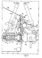
- reference letters NS indicate a web of wrapping material, in particular a cigarette paper web, coming from a bobbin (not shown) and fed, in the direction of arrow F of figure 1, to a machine, for example a machine for cigarette wrapping (not shown).
- the web NS being unwound passes through a roller 1 and around a roller 2.
- the portion of web NS between rollers 1 and 2 is substantially vertical but it may have any other direction.
- NR indicates a similar web coming from a standby bobbin (not shown). The leading end of the standby web NR is connected to the tail of pay-off web NS when the bobbin of web NS is depleted.
- the device for splicing webs NS and NR includes two splicing heads GS and GR located on opposed sides of the path of web NS between roller 1 upstream and roller 2 downstream the splicing head GS.
- Splicing head GR is associated to an upstream roller 3 for web NR.
- the two splicing heads GS and GR are identical and alternately work in the same way. Consequently a description of splicing head GS only will follow, including the parts associated to it and the same reference numbers will indicate also the elements of the other splicing head GR and the parts associated thereto.
- Each splicing head GS and GR is formed by a suction presser 4 integral with piston 5 of a simple action pneumatic cylinder equipped with spring return 7. This means that the suction presser 4 is pulled forward by the compressed air of cylinder 6 while a pressure spring 7 interposed between the body of cylinder 6 and a rear extension 9 of piston 5 keeps back this latter together with suction presser 7 when the pneumatic pressure in cylinder 6 stops.
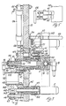
- Cylinder 6 is mounted in overhanging manner onto a transversal pivot 10 revolving and axially sliding by means of ball sleeves 11 ' in a tube 12 connected to a supporting plate 13.
- Compressed air is supplied to chamber 20 of cylinder 6 mounted on the back side of piston 5 by connection 14 and a longitudinal slot 15 in pivot 10. Suction is instead applied by connection 16 and by an annular chamber 17 located on the upper side of piston 5 and connected, by means of radial holes 18, to a chamber 19 mounted behind the flat head provided with holes of presser 4.
- Cylinder 6 of each splicing head GS, GR is provided with an arm 21 bringing the relevant roller 1, 3 of web NS, NR and its respective web-pinching finger 101, 103.
- Web NS coming from its bobbin passes through roller 1 and respective web-pinching finger 101, while web NR from the standby bobbin is passed between roller 3 and web-pinching finger 103.
- Each web-pinching finger 101, 103 is assembled on a pivot 22 and swinging on the respective support integral with arm 21 and is pulled by a spring 23 towards its corresponding roller 1,3. Due to spring 23 each web-pinching finger 101, 103 can have a locking position in which it locks the respective web NS, NR on the corresponding roller 1, 3.
- each . splicing head GS, GR swings, together with roller 1, 3 and respective web-pinching finger 101, 103, around a transversal axis formed by pivot 10, and moves with pivot 10 along the above said axis and transversally to the relevant plane of web NS, NR, that is in the direction of the width of the web itself.
- a pneumatic cylinder 24 provides for the angular movement of each splicing head GS, GR i.e. of the respective cylinder 6 around the transversal pivot 10, the cylinder being mounted swinging on pivot 25 to supporting plate 13 while its shaft 26 is fitted to the end 127 of a pivot 27 integral to arm 28 of a sleeve 29 assembled and revolving around tube 12 coaxially to pivot 10.
- Pivot 27 slides through a curved slot 30 located in the supporting plate 13 coaxially to pivot 10.
- arm 28 of revolving sleeve 29 is provided with a dragging pin 31 which engages in rotatable manner and slides longitudinally by means of a ball sleeve 32 in a cylindrical housing over arm 21 of cylinder 6.
- each splicing head GS can be angularly shifted around the axis of the respective transversal pivot 10 and together with pivot 10 so as to reach alternately an angular working position in which the face of suction presser 4 is substantially parallel to web NS of the pay-off bobbin, passed around roller 2 downstream and fed to the user machine as shown for splicing head GS, and an angular rest position in which the face of suction presser 4 is inclined outwardly with respect to the path of the web NS being unrolled and is, for example, facing upwardly as shown for splicing head GR.
- Splicing head GS of web NS of the pay-off bobbin is in the above mentioned angular working position and suction through its presser 4 is interrupted.
- An extension 34 of web pinching finger 101 cooperating with roller 1 of splicing head GS touches, in this working position of splicing head GS, an adjustable screw 35 that causes web-pinching finger 101 swinging on fulcrum 22 lifting it - by the action of spring 23, from its respective roller 1.
- Web NS of the bobbin.being unrolled passes freely between roller 1 and its respective lifted web-pinching finger 101 as shown in figure 1.
- Splicing head GR connected to web NR of the standby bobbin is in the above described angular rest position and suction, through presser 4, is carried out.
- the leading end of web NR of the standby bobbin is provided with an label L adhesive on both sides and is applied to suction presser 4 which holds it by sucking.
- pressers 4 are facing and opposed to the interposed webs NS and NR. Compressed air is fed to chamber 20 of cylinder 6 of splicing head GS and presser 4 of this head is pushed against the presser of the opposite head GR, thus connecting the leading end of web NR to web NS by the interposed adhesive label L.
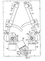
- presser 4 of splicing head GS causes the cutting of thqend of web NS by a fixed blade 36 located between the two splicing heads GS and GR on a stationary support, the edges of which are facing the splicing heads GS and GR and are saw-shaped as shown in detail by figures 1, 2 and 6.
- suction is stopped by presser 4 of splicing head GR that remains in .
- the next splicing operation is carried out as above explained with inverted functions of the two splicing heads.
- the possibility of a rectilinear shifting of the splicing heads GS and GR together with the corresponding roller 1, 3 of the respective web-pinching finger 101, 103 axially to pivot 10 and in the direction of the width of webs NS, NR serves to guarantee the mutual alignment of web NS, NR to be spliced.
- each splicing head GS, GR is obtained by a stepping electric motor 38 moving a roller 39 eccentrically pivoted to shaft 138 of motor 38 and connected to the peripheral ring slot of a dragging collar 40 which is mounted freely revolving but not axially sliding on the bottom end 110 of pivot 10.
- roller 39 By shifting roller 39 with the relevant stepping motor 38, collar 40 drags and axially shifts, in one direction or the other, pivot 10 together with cylinder 6 and arm 21 carrying the associated roller 1 or 3 and the respective web-pinching finger 101, 103.
- Axial shifting of each roller 1, 3 causes the corresponding shifting of the respective web NS, NR in the direction of the width as web NS, NR is friction dragged by roller 1, 3 also when it is not blocked on it by the respective web-pinching finger 101, 103.
- each splicing head GS GR is operatively coupled to its respective actuator cylinder for its angular shifting due to the axially sliding assembly of dragging pin 31 in its relevant cylindrical housing 33 on arm 21.
- Direction and amplitude of movement of each stepping motor 38 are controlled by a sensor associated to each splicing head GS, GR and sensible to the transversal position of relevant webs NS, NR with respect to a pre-set transversal position of perfect mutual alignmento of the two webs NS, NR.
- this sensor is formed by two fork photocells 41, 42 which are assembled on the arm 28 of the revolving sleeve 29 on the fixed tube 12 of pivot 10 and are placed one after the other in the longitudinal direction of respective web NS, NR.
- One arm of the fork of each photocell 41, 42 is equipped with a light emitter, while the other arm of the fork, facing the light emitter, is equipped with its respective photosensible receiver.
- Web NS, NR associated to each splicing head GS, GR passes with its edge through the two subsequent fork photocells 41, 42.
- the two fork photocells 41, 42 are slightly off-set one with respect to the other in the direction of the width of web NS, NR.
- the invention includes an axial shifting of downstream roller 2 in the direction of the width of the web together with splicing head GS corresponding to the web NS of the depleted bobbin, in the same direction and measure and controlled by the couple of photocells 41, 42 associated to splicing head GS.
- roller 2 is rotatably mounted on pivot 43 supported and axially sliding on ball sleeves 44 in a tube 45 assembled to the supporting plate 13.
- the rear end 143 of pivot 43 is fork--shaped and is sliding, by means of ball sleeves 47, on a pin 46 fixed to head 145 of tube 45.
- the fork end 143 of pivot 43 is engaged by a small roller 48 eccentrically pivoted to shaft 149 of a stepping motor 49, as shown by figure 4.
- Stepping motor 49 effecting the axial shifting of pivot 43 and roller 2 is controlled by a couple of photocells 41, 42 of the splicing head being in the working position and associated to the web of the depleted bobbin, so as to shift roller 2 axially in the same direction and measure of the said splicing head and consequently of the respective roller 1 or 3.
Landscapes
- Replacement Of Web Rolls (AREA)
Applications Claiming Priority (2)
| Application Number | Priority Date | Filing Date | Title |
|---|---|---|---|
| IT1255984 | 1984-07-10 | ||
| IT12559/84A IT1180789B (it) | 1984-07-10 | 1984-07-10 | Dispositivo per la giunzione di nastri in particolare di nastri di carta da sigarette |
Publications (2)
| Publication Number | Publication Date |
|---|---|
| EP0167917A1 true EP0167917A1 (fr) | 1986-01-15 |
| EP0167917B1 EP0167917B1 (fr) | 1988-02-24 |
Family
ID=11141594
Family Applications (1)
| Application Number | Title | Priority Date | Filing Date |
|---|---|---|---|
| EP85107824A Expired EP0167917B1 (fr) | 1984-07-10 | 1985-06-24 | Dispositif de collage de rubans, notamment de rubans de papier à cigarettes |
Country Status (3)
| Country | Link |
|---|---|
| EP (1) | EP0167917B1 (fr) |
| DE (1) | DE3561651D1 (fr) |
| IT (1) | IT1180789B (fr) |
Cited By (8)
| Publication number | Priority date | Publication date | Assignee | Title |
|---|---|---|---|---|
| WO1990001012A1 (fr) * | 1988-07-19 | 1990-02-08 | Stork Contiweb B.V. | Dispositif servant a relier entre elles deux bandes |
| EP0622318A1 (fr) * | 1993-04-08 | 1994-11-02 | Japan Tobacco Inc. | Appareil pour rabouter automatiquement un matériau en bande |
| WO1995013235A1 (fr) * | 1993-11-11 | 1995-05-18 | Packline Limited | Systeme d'emballage |
| EP0780331A3 (fr) * | 1995-12-20 | 1997-08-20 | Eastman Kodak Co | Dispositif et procédé pour aligner des bandes |
| US5913991A (en) * | 1996-02-15 | 1999-06-22 | Fuji Photo Film Co., Ltd. | Splicing device and splicing method |
| WO2005110903A1 (fr) * | 2004-04-30 | 2005-11-24 | Kimberly-Clark Worldwide, Inc. | Appareil et processus d’alignement des matériaux pendant un raccord |
| EP1842814A3 (fr) * | 2006-04-03 | 2008-06-04 | UHLMANN PAC-SYSTEME GmbH & Co. KG | Dispositif pour remplacer une première bande de matériau par une deuxième bande de matériau |
| CN116161466A (zh) * | 2023-02-10 | 2023-05-26 | 深圳市新晶路电子科技有限公司 | 不停机放料装置及运行方法 |
Families Citing this family (1)
| Publication number | Priority date | Publication date | Assignee | Title |
|---|---|---|---|---|
| DE102022119212A1 (de) * | 2022-08-01 | 2024-02-01 | Körber Technologies Gmbh | Vorrichtung und Verfahren zum Verbinden von endlichen Materialbahnen |
Citations (3)
| Publication number | Priority date | Publication date | Assignee | Title |
|---|---|---|---|---|
| US3753381A (en) * | 1971-12-10 | 1973-08-21 | Eickhoff Geb | Web edge control for strip processing lines |
| DE2701438A1 (de) * | 1976-01-14 | 1977-07-21 | Amf Inc | Vorrichtung zur selbsttaetigen verbindung zweier papierbaender, insbesondere fuer zigarettenherstellungsmaschinen |
| EP0067481A2 (fr) * | 1981-06-11 | 1982-12-22 | Tevopharm Schiedam B.V. | Arbre comportant des moyens pour retenir une bobine, rouleau de matériau ou article analogue |
Family Cites Families (1)
| Publication number | Priority date | Publication date | Assignee | Title |
|---|---|---|---|---|
| US3030043A (en) * | 1958-07-10 | 1962-04-17 | American Mach & Foundry | Web splicer for cigarette machine |
-
1984
- 1984-07-10 IT IT12559/84A patent/IT1180789B/it active
-
1985
- 1985-06-24 DE DE8585107824T patent/DE3561651D1/de not_active Expired
- 1985-06-24 EP EP85107824A patent/EP0167917B1/fr not_active Expired
Patent Citations (3)
| Publication number | Priority date | Publication date | Assignee | Title |
|---|---|---|---|---|
| US3753381A (en) * | 1971-12-10 | 1973-08-21 | Eickhoff Geb | Web edge control for strip processing lines |
| DE2701438A1 (de) * | 1976-01-14 | 1977-07-21 | Amf Inc | Vorrichtung zur selbsttaetigen verbindung zweier papierbaender, insbesondere fuer zigarettenherstellungsmaschinen |
| EP0067481A2 (fr) * | 1981-06-11 | 1982-12-22 | Tevopharm Schiedam B.V. | Arbre comportant des moyens pour retenir une bobine, rouleau de matériau ou article analogue |
Cited By (13)
| Publication number | Priority date | Publication date | Assignee | Title |
|---|---|---|---|---|
| US5207859A (en) * | 1988-07-19 | 1993-05-04 | Stork Contiweb B.V. | Device for interconnecting two webs of material |
| WO1990001012A1 (fr) * | 1988-07-19 | 1990-02-08 | Stork Contiweb B.V. | Dispositif servant a relier entre elles deux bandes |
| US6244321B1 (en) | 1993-04-08 | 2001-06-12 | Japan Tobacco, Inc. | Automatic web material connecting apparatus |
| EP0622318A1 (fr) * | 1993-04-08 | 1994-11-02 | Japan Tobacco Inc. | Appareil pour rabouter automatiquement un matériau en bande |
| WO1995013235A1 (fr) * | 1993-11-11 | 1995-05-18 | Packline Limited | Systeme d'emballage |
| EP0780331A3 (fr) * | 1995-12-20 | 1997-08-20 | Eastman Kodak Co | Dispositif et procédé pour aligner des bandes |
| US5849123A (en) * | 1995-12-20 | 1998-12-15 | Eastman Kodak Company | Apparatus and method for aligning webs |
| US6192955B1 (en) | 1995-12-20 | 2001-02-27 | Eastman Kodak Company | Apparatus and method for aligning webs |
| US5913991A (en) * | 1996-02-15 | 1999-06-22 | Fuji Photo Film Co., Ltd. | Splicing device and splicing method |
| WO2005110903A1 (fr) * | 2004-04-30 | 2005-11-24 | Kimberly-Clark Worldwide, Inc. | Appareil et processus d’alignement des matériaux pendant un raccord |
| EP1842814A3 (fr) * | 2006-04-03 | 2008-06-04 | UHLMANN PAC-SYSTEME GmbH & Co. KG | Dispositif pour remplacer une première bande de matériau par une deuxième bande de matériau |
| US7621479B2 (en) | 2006-04-03 | 2009-11-24 | Uhlmann Pac-Systeme Gmbh & Co. Kg | Supply-roll switching apparatus |
| CN116161466A (zh) * | 2023-02-10 | 2023-05-26 | 深圳市新晶路电子科技有限公司 | 不停机放料装置及运行方法 |
Also Published As
| Publication number | Publication date |
|---|---|
| IT1180789B (it) | 1987-09-23 |
| EP0167917B1 (fr) | 1988-02-24 |
| IT8412559A0 (it) | 1984-07-10 |
| DE3561651D1 (en) | 1988-03-31 |
Similar Documents
| Publication | Publication Date | Title |
|---|---|---|
| US4738743A (en) | Apparatus for applying tire material | |
| US4224824A (en) | Detecting device for breaks or tears and for the end of the strip in a strip of any material during its advance | |
| US4652329A (en) | Apparatus for joining sheets of packaging material | |
| US4555281A (en) | Method for automatically setting and joining reel-fed label strips or similar | |
| US4315794A (en) | Device for the quick splicing of paper webs | |
| EP0167917A1 (fr) | Dispositif de collage de rubans, notamment de rubans de papier à cigarettes | |
| US4729522A (en) | Web handling apparatus | |
| GB2135283A (en) | Splicing webs | |
| US4695007A (en) | Apparatus for continuously supplying sheets from supply rolls | |
| JPH04242521A (ja) | ストリップ材料の取替え方法 | |
| US5129294A (en) | Method of replacing and adjusting preprinted strip material on a manufacturing machine | |
| US4729519A (en) | Web handling apparatus | |
| US4821973A (en) | Apparatus and method for activating a device for operating on a moving workpiece | |
| US3953278A (en) | Sticker applicator | |
| FI900344A0 (fi) | Anordning foer sammanbindning av materialbana. | |
| CA2050481C (fr) | Appareil pour former des joints | |
| US6758431B2 (en) | Device for linking two webs of material | |
| US4706586A (en) | Automatic sewing machine having a post-arranged reel | |
| US5067646A (en) | Apparatus for controlling a web | |
| EP0728690B1 (fr) | Machine pour déployer du tissu | |
| US3608797A (en) | Sensing means for controlling felt guides | |
| CA1065196A (fr) | Machine a coudre | |
| US5031552A (en) | Drive assembly for seam-forming apparatus | |
| EP0395028B1 (fr) | Dispositif de jonction de bandes de matériaux | |
| US5234532A (en) | Apparatus for connecting paper web with a paper web threading member |
Legal Events
| Date | Code | Title | Description |
|---|---|---|---|
| PUAI | Public reference made under article 153(3) epc to a published international application that has entered the european phase |
Free format text: ORIGINAL CODE: 0009012 |
|
| AK | Designated contracting states |
Designated state(s): CH DE FR GB LI NL SE |
|
| 17P | Request for examination filed |
Effective date: 19860311 |
|
| 17Q | First examination report despatched |
Effective date: 19861007 |
|
| D17Q | First examination report despatched (deleted) | ||
| GRAA | (expected) grant |
Free format text: ORIGINAL CODE: 0009210 |
|
| AK | Designated contracting states |
Kind code of ref document: B1 Designated state(s): CH DE FR GB LI NL SE |
|
| PG25 | Lapsed in a contracting state [announced via postgrant information from national office to epo] |
Ref country code: NL Effective date: 19880224 Ref country code: LI Effective date: 19880224 Ref country code: CH Effective date: 19880224 |
|
| PG25 | Lapsed in a contracting state [announced via postgrant information from national office to epo] |
Ref country code: SE Effective date: 19880229 |
|
| REF | Corresponds to: |
Ref document number: 3561651 Country of ref document: DE Date of ref document: 19880331 |
|
| ET | Fr: translation filed | ||
| REG | Reference to a national code |
Ref country code: CH Ref legal event code: PL |
|
| NLV1 | Nl: lapsed or annulled due to failure to fulfill the requirements of art. 29p and 29m of the patents act | ||
| PLBE | No opposition filed within time limit |
Free format text: ORIGINAL CODE: 0009261 |
|
| STAA | Information on the status of an ep patent application or granted ep patent |
Free format text: STATUS: NO OPPOSITION FILED WITHIN TIME LIMIT |
|
| 26N | No opposition filed | ||
| PGFP | Annual fee paid to national office [announced via postgrant information from national office to epo] |
Ref country code: GB Payment date: 19920512 Year of fee payment: 8 |
|
| PGFP | Annual fee paid to national office [announced via postgrant information from national office to epo] |
Ref country code: FR Payment date: 19920513 Year of fee payment: 8 |
|
| PGFP | Annual fee paid to national office [announced via postgrant information from national office to epo] |
Ref country code: DE Payment date: 19920722 Year of fee payment: 8 |
|
| PG25 | Lapsed in a contracting state [announced via postgrant information from national office to epo] |
Ref country code: GB Effective date: 19930624 |
|
| GBPC | Gb: european patent ceased through non-payment of renewal fee |
Effective date: 19930624 |
|
| PG25 | Lapsed in a contracting state [announced via postgrant information from national office to epo] |
Ref country code: FR Effective date: 19940228 |
|
| PG25 | Lapsed in a contracting state [announced via postgrant information from national office to epo] |
Ref country code: DE Effective date: 19940301 |
|
| REG | Reference to a national code |
Ref country code: FR Ref legal event code: ST |