EP0167921A2 - Pulvérisateur à jet plat pour la refroidissement de billettes convoyées continûment dans une installation de coulée continue - Google Patents
Pulvérisateur à jet plat pour la refroidissement de billettes convoyées continûment dans une installation de coulée continue Download PDFInfo
- Publication number
- EP0167921A2 EP0167921A2 EP85107858A EP85107858A EP0167921A2 EP 0167921 A2 EP0167921 A2 EP 0167921A2 EP 85107858 A EP85107858 A EP 85107858A EP 85107858 A EP85107858 A EP 85107858A EP 0167921 A2 EP0167921 A2 EP 0167921A2
- Authority
- EP
- European Patent Office
- Prior art keywords
- jet nozzle
- flat jet
- coolant
- strand
- width
- Prior art date
- Legal status (The legal status is an assumption and is not a legal conclusion. Google has not performed a legal analysis and makes no representation as to the accuracy of the status listed.)
- Granted
Links
Images
Classifications
-
- B—PERFORMING OPERATIONS; TRANSPORTING
- B05—SPRAYING OR ATOMISING IN GENERAL; APPLYING FLUENT MATERIALS TO SURFACES, IN GENERAL
- B05B—SPRAYING APPARATUS; ATOMISING APPARATUS; NOZZLES
- B05B1/00—Nozzles, spray heads or other outlets, with or without auxiliary devices such as valves, heating means
- B05B1/26—Nozzles, spray heads or other outlets, with or without auxiliary devices such as valves, heating means with means for mechanically breaking-up or deflecting the jet after discharge, e.g. with fixed deflectors; Breaking-up the discharged liquid or other fluent material by impinging jets
- B05B1/262—Nozzles, spray heads or other outlets, with or without auxiliary devices such as valves, heating means with means for mechanically breaking-up or deflecting the jet after discharge, e.g. with fixed deflectors; Breaking-up the discharged liquid or other fluent material by impinging jets with fixed deflectors
- B05B1/267—Nozzles, spray heads or other outlets, with or without auxiliary devices such as valves, heating means with means for mechanically breaking-up or deflecting the jet after discharge, e.g. with fixed deflectors; Breaking-up the discharged liquid or other fluent material by impinging jets with fixed deflectors the liquid or other fluent material being deflected in determined directions
-
- B—PERFORMING OPERATIONS; TRANSPORTING
- B22—CASTING; POWDER METALLURGY
- B22D—CASTING OF METALS; CASTING OF OTHER SUBSTANCES BY THE SAME PROCESSES OR DEVICES
- B22D11/00—Continuous casting of metals, i.e. casting in indefinite lengths
- B22D11/12—Accessories for subsequent treating or working cast stock in situ
- B22D11/124—Accessories for subsequent treating or working cast stock in situ for cooling
- B22D11/1246—Nozzles; Spray heads
-
- B—PERFORMING OPERATIONS; TRANSPORTING
- B05—SPRAYING OR ATOMISING IN GENERAL; APPLYING FLUENT MATERIALS TO SURFACES, IN GENERAL
- B05B—SPRAYING APPARATUS; ATOMISING APPARATUS; NOZZLES
- B05B1/00—Nozzles, spray heads or other outlets, with or without auxiliary devices such as valves, heating means
- B05B1/02—Nozzles, spray heads or other outlets, with or without auxiliary devices such as valves, heating means designed to produce a jet, spray, or other discharge of particular shape or nature, e.g. in single drops, or having an outlet of particular shape
- B05B1/04—Nozzles, spray heads or other outlets, with or without auxiliary devices such as valves, heating means designed to produce a jet, spray, or other discharge of particular shape or nature, e.g. in single drops, or having an outlet of particular shape in flat form, e.g. fan-like, sheet-like
Definitions
- the invention relates to a method for cooling continuously conveyed casting strands in a continuous casting installation, wherein coolant jets emerging from a nozzle slot strike the strand surface at different angles across the width of the casting strand.
- the invention also relates to a flat jet nozzle for performing the method.
- the object of the invention is to provide a simple method for cooling casting strands with a coolant quantity distribution over the strand width which effects a uniform, gentle and rapid cooling of the strand surface.
- This object is achieved according to the invention in that cooling directed at width regions of the strand surface average quantities Q are measured taking into account their impact angle ⁇ in the sense of uniform heat dissipation.
- the amounts of coolant directed towards the width regions of the strand surface are dimensioned according to the angle of impact and the mixed state in the respective region of impact.
- the mixed state is to be understood as the mixing ratio and the water droplet size upon impact.
- the width of an outlet slot is determined at every point according to the angle of incidence of the emerging coolant jet.
- the outlet slot can extend in front of an impact surface in the circumferential direction of the flat jet nozzle.
- the outlet slot can be arranged parallel to the inflow opening on the side of the flat jet nozzle.
- a particularly cost-effective design of the flat jet nozzle is seen in the fact that the outlet slot is partially placed on a side bore of the flat jet nozzle Cover is formed, which is fastened by a bolt penetrating the side bore.
- the flat jet nozzle can advantageously be arranged on a mixing valve provided with cooling water connection and air connection for two-substance cooling.
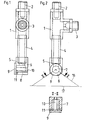
- a T-shaped mixing valve 1 is provided with a connecting nipple 2, 3 each for an air supply line and a water supply line.
- a nozzle tube 4, to which a flat jet nozzle 5 is connected, is screwed in on an outlet side of the mixer fitting 1.
- the flat jet nozzle 5 is provided with an inlet opening 6 and a side bore 7 at right angles thereto, the lower wall 8 of which acts as an impact surface.
- the side bore 7 is provided with a cover 9, which is fastened to the opposite wall of the flat jet nozzle 5 by a bolt 10 penetrating the side bore 7.
- the lower wall 8 of the flat jet nozzle 5 is angularly excluded to form an outlet slot 11 on the side of the cover 9.
- a flat jet nozzle 13 screwed to a nozzle tube 12 is provided with an outlet slot 15 in its wall immediately in front of an impact surface 14 on the end face.
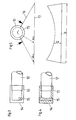
- the coolant is sprayed through the outlet slots 11, 15 of the flat jet nozzle 5 or 13 in a fan 16 onto a casting strand surface 17, with individual coolant jets of the spray fan 16 having different angles of incidence, ⁇ 2 .
- different amounts of coolant Q are defined for the width regions depending on the angle of incidence d.
- the associated area of the outlet slot 11, 15 is defined in terms of its width according to the required coolant quantities Q. It can be seen from FIGS. 1 to 4 that the width of the outlet slots 11, 15 increases from the center to the sides. In this way, the outer regions of a cast strand surface 17 are subjected to a larger quantity of coolant Q in an increasingly defined manner to the outside (FIG. 5).
Landscapes
- Engineering & Computer Science (AREA)
- Mechanical Engineering (AREA)
- Continuous Casting (AREA)
- Nozzles (AREA)
Priority Applications (1)
| Application Number | Priority Date | Filing Date | Title |
|---|---|---|---|
| AT85107858T ATE33775T1 (de) | 1984-07-07 | 1985-06-25 | Flachstrahlduese zum kuehlen von kontinuierlich gefoerderten giesstraengen in einer stranggiessanlage. |
Applications Claiming Priority (2)
| Application Number | Priority Date | Filing Date | Title |
|---|---|---|---|
| DE3425092 | 1984-07-07 | ||
| DE3425092A DE3425092A1 (de) | 1984-07-07 | 1984-07-07 | Verfahren und vorrichtung zum kuehlen von kontinuierlich gefoerderten giessstraengen in einer stranggiessanlage |
Publications (3)
| Publication Number | Publication Date |
|---|---|
| EP0167921A2 true EP0167921A2 (fr) | 1986-01-15 |
| EP0167921A3 EP0167921A3 (en) | 1986-10-08 |
| EP0167921B1 EP0167921B1 (fr) | 1988-04-27 |
Family
ID=6240095
Family Applications (1)
| Application Number | Title | Priority Date | Filing Date |
|---|---|---|---|
| EP85107858A Expired EP0167921B1 (fr) | 1984-07-07 | 1985-06-25 | Pulvérisateur à jet plat pour la refroidissement de billettes convoyées continûment dans une installation de coulée continue |
Country Status (5)
| Country | Link |
|---|---|
| US (1) | US4641785A (fr) |
| EP (1) | EP0167921B1 (fr) |
| JP (1) | JPS6130269A (fr) |
| AT (1) | ATE33775T1 (fr) |
| DE (2) | DE3425092A1 (fr) |
Cited By (2)
| Publication number | Priority date | Publication date | Assignee | Title |
|---|---|---|---|---|
| AU598009B2 (en) * | 1986-12-08 | 1990-06-14 | Wagstaff Engineering, Inc. | Means and technique for casting metals |
| US5836377A (en) * | 1994-03-04 | 1998-11-17 | Mannesmann Aktiengesellschaft | Process and device for cooling molten steel |
Families Citing this family (18)
| Publication number | Priority date | Publication date | Assignee | Title |
|---|---|---|---|---|
| US6371596B1 (en) | 1995-10-25 | 2002-04-16 | Hewlett-Packard Company | Asymmetric ink emitting orifices for improved inkjet drop formation |
| US6123413A (en) * | 1995-10-25 | 2000-09-26 | Hewlett-Packard Company | Reduced spray inkjet printhead orifice |
| AT409940B (de) * | 2001-02-20 | 2002-12-27 | Voest Alpine Ind Anlagen | Zweistoff-schaftdüse und stranggiessanlage mit einer anordnung von zweistoff-schaftdüsen |
| US6574094B1 (en) | 2002-04-11 | 2003-06-03 | General Dynamics Land Systems Inc. | Method and apparatus for cooling bus bars |
| US6625023B1 (en) | 2002-04-11 | 2003-09-23 | General Dynamics Land Systems, Inc. | Modular spray cooling system for electronic components |
| JP4594033B2 (ja) * | 2004-10-26 | 2010-12-08 | 株式会社大気社 | 空調用吹出器具、及び、それに使用する吐出部形成用筒体 |
| US7379487B2 (en) | 2005-02-14 | 2008-05-27 | Neumann Information Systems, Inc. | Two phase reactor |
| US7866638B2 (en) * | 2005-02-14 | 2011-01-11 | Neumann Systems Group, Inc. | Gas liquid contactor and effluent cleaning system and method |
| US8864876B2 (en) * | 2005-02-14 | 2014-10-21 | Neumann Systems Group, Inc. | Indirect and direct method of sequestering contaminates |
| US8113491B2 (en) | 2005-02-14 | 2012-02-14 | Neumann Systems Group, Inc. | Gas-liquid contactor apparatus and nozzle plate |
| US8398059B2 (en) | 2005-02-14 | 2013-03-19 | Neumann Systems Group, Inc. | Gas liquid contactor and method thereof |
| JP5104536B2 (ja) | 2008-05-16 | 2012-12-19 | マックス株式会社 | 燃料充填容器及びガス燃焼式打込み工具 |
| JP5578206B2 (ja) * | 2012-08-03 | 2014-08-27 | マックス株式会社 | 燃料充填容器及びガス燃焼式打込み工具 |
| FR3031033B1 (fr) * | 2014-12-30 | 2017-11-10 | Steris | Bras d'aspersion, notamment pour un dispositif de lavage d'articles |
| DE102015204664A1 (de) * | 2015-03-16 | 2016-09-22 | Lechler Gmbh | Flachstrahldüse und Verwendung einer Flachstrahldüse |
| US10350617B1 (en) * | 2016-02-12 | 2019-07-16 | Konstantin Dragan | Composition of and nozzle for spraying a single-component polyurethane foam |
| US10702876B2 (en) * | 2016-06-03 | 2020-07-07 | Konstantin Dragan | System, composition, and method for dispensing a sprayable foamable product |
| US10815353B1 (en) | 2016-06-03 | 2020-10-27 | Konstantin Dragan | Composition of and nozzle for spraying a single-component polyurethane foam |
Family Cites Families (10)
| Publication number | Priority date | Publication date | Assignee | Title |
|---|---|---|---|---|
| US2746795A (en) * | 1953-04-16 | 1956-05-22 | R B Mfg Corp | Diffusing apparatus |
| US3877510A (en) * | 1973-01-16 | 1975-04-15 | Concast Inc | Apparatus for cooling a continuously cast strand incorporating coolant spray nozzles providing controlled spray pattern |
| US3935896A (en) * | 1973-01-16 | 1976-02-03 | Concast Incorporated | Method for cooling a continuously cast strand |
| LU71487A1 (fr) * | 1974-01-04 | 1975-06-17 | ||
| AT327418B (de) * | 1974-01-17 | 1976-01-26 | Voest Ag | Strahlduse |
| DE2816441C2 (de) * | 1978-04-15 | 1982-01-14 | Lechler Gmbh & Co Kg, 7012 Fellbach | Vorrichtung zum Aufsprühen eines Treib- und Kühlmittels auf eine Strangguß-Stahlbramme |
| DE3004864C2 (de) * | 1980-02-09 | 1983-12-29 | Lechler Gmbh & Co Kg, 7012 Fellbach | Vorrichtung zum Aufsprühen eines Treib- und Kühl-Mittelgemisches auf Gußstränge |
| JPS5719144A (en) * | 1980-07-10 | 1982-02-01 | Nippon Steel Corp | Conveying method for high-temperature ingot |
| JPS59135852U (ja) * | 1983-02-25 | 1984-09-11 | 株式会社神戸製鋼所 | 連続鋳造設備に用いる冷却用ミスト噴出装置 |
| US4567934A (en) * | 1983-02-28 | 1986-02-04 | Kabushiki Kaisha Kobe Seiko Sho | Cooling mechanism for use in continuous metal casting |
-
1984
- 1984-07-07 DE DE3425092A patent/DE3425092A1/de not_active Withdrawn
-
1985
- 1985-06-25 EP EP85107858A patent/EP0167921B1/fr not_active Expired
- 1985-06-25 AT AT85107858T patent/ATE33775T1/de not_active IP Right Cessation
- 1985-06-25 DE DE8585107858T patent/DE3562322D1/de not_active Expired
- 1985-07-05 JP JP14689685A patent/JPS6130269A/ja active Pending
- 1985-07-08 US US06/752,939 patent/US4641785A/en not_active Expired - Fee Related
Cited By (2)
| Publication number | Priority date | Publication date | Assignee | Title |
|---|---|---|---|---|
| AU598009B2 (en) * | 1986-12-08 | 1990-06-14 | Wagstaff Engineering, Inc. | Means and technique for casting metals |
| US5836377A (en) * | 1994-03-04 | 1998-11-17 | Mannesmann Aktiengesellschaft | Process and device for cooling molten steel |
Also Published As
| Publication number | Publication date |
|---|---|
| EP0167921A3 (en) | 1986-10-08 |
| DE3562322D1 (en) | 1988-06-01 |
| EP0167921B1 (fr) | 1988-04-27 |
| JPS6130269A (ja) | 1986-02-12 |
| DE3425092A1 (de) | 1986-02-06 |
| ATE33775T1 (de) | 1988-05-15 |
| US4641785A (en) | 1987-02-10 |
Similar Documents
| Publication | Publication Date | Title |
|---|---|---|
| EP0167921A2 (fr) | Pulvérisateur à jet plat pour la refroidissement de billettes convoyées continûment dans une installation de coulée continue | |
| DE3131070C2 (fr) | ||
| DE69229962T2 (de) | Ausrüstung zur brandbekämpfung | |
| DE2939951C2 (fr) | ||
| DE2401649B2 (de) | Verfahren zum kuehlen eines stranges und spruehduese | |
| DE1427597A1 (de) | Farbspritzkanal fuer die Spritzbehandlung verhaeltnismaessig grosser Werkstuecke | |
| DE2312311A1 (de) | Druckluftpistole | |
| DE69715678T2 (de) | Verbesserte beimischvorrichtung mit belüfter | |
| DE3419423A1 (de) | Spruehduese | |
| EP1047504A1 (fr) | Buse a jet eventail destine a pulveriser un liquide de refroidissement sur un produit de coulee continue | |
| DD296345A5 (de) | Trapezfoermiger luftauslasskasten | |
| DE2816441A1 (de) | Vorrichtung zum aufspruehen eines kuehlmittels auf stahlbrammen beim stranggiessen | |
| DE1577634C3 (de) | Vorrichtung zur nassen Farbtropfenabscheidung in einer Farbspritzanlage | |
| EP0107831A1 (fr) | Dispositif pour la pulvérisation d'un mélange d'agents d'entraînement et de refroidissement sur une billette en acier coulé | |
| DE2138539C3 (de) | Luftauslaßeinrichtung | |
| DE602005005568T2 (de) | Düsenplatte zum Zerstäuben von Flüssigkeiten, Verfahren zum Herstellen von Düsenplatten und Gebrauch einer Düsenplatte | |
| DE3004864A1 (de) | Vorrichtung zum aufspruehen eines kuehlmittels auf stahlbrammen | |
| DE2303430C3 (de) | Vorrichtung zum Reinigen von gasförmigen Stoffen, welche Farbstoff, Lack bzw. Zellulose enthalten | |
| DE8900464U1 (de) | Dampfkühleinrichtung | |
| DE2751013A1 (de) | Kuehleinrichtung | |
| DE2548754A1 (de) | Verfahren und vorrichtung zum einbringen von luft in fluessigkeiten, insbesondere fuer die abwasserbelueftung | |
| DE2447607A1 (de) | Vorrichtung zur vergroesserung des sauerstoffgehaltes in einem stroemenden gewaesser | |
| DE1778261C3 (de) | Vorrichtung zum Abziehen von Farbe aus der Luft in einem Farbspritzstand | |
| DE2836113A1 (de) | Spritzsystem fuer verteilung von fluessigkeit, insbesondere fuer biofilterbetten, kuehltuerme u.dgl. | |
| DE3880550T2 (de) | Feuchtduese fuer druckmaschine. |
Legal Events
| Date | Code | Title | Description |
|---|---|---|---|
| PUAI | Public reference made under article 153(3) epc to a published international application that has entered the european phase |
Free format text: ORIGINAL CODE: 0009012 |
|
| 17P | Request for examination filed |
Effective date: 19850722 |
|
| AK | Designated contracting states |
Designated state(s): AT CH DE FR GB LI LU |
|
| PUAL | Search report despatched |
Free format text: ORIGINAL CODE: 0009013 |
|
| AK | Designated contracting states |
Kind code of ref document: A3 Designated state(s): AT CH DE FR GB LI LU |
|
| 17Q | First examination report despatched |
Effective date: 19870430 |
|
| GRAA | (expected) grant |
Free format text: ORIGINAL CODE: 0009210 |
|
| AK | Designated contracting states |
Kind code of ref document: B1 Designated state(s): AT CH DE FR GB LI LU |
|
| REF | Corresponds to: |
Ref document number: 33775 Country of ref document: AT Date of ref document: 19880515 Kind code of ref document: T |
|
| REF | Corresponds to: |
Ref document number: 3562322 Country of ref document: DE Date of ref document: 19880601 |
|
| PG25 | Lapsed in a contracting state [announced via postgrant information from national office to epo] |
Ref country code: LU Free format text: LAPSE BECAUSE OF NON-PAYMENT OF DUE FEES Effective date: 19880630 |
|
| ET | Fr: translation filed | ||
| GBT | Gb: translation of ep patent filed (gb section 77(6)(a)/1977) | ||
| PLBE | No opposition filed within time limit |
Free format text: ORIGINAL CODE: 0009261 |
|
| STAA | Information on the status of an ep patent application or granted ep patent |
Free format text: STATUS: NO OPPOSITION FILED WITHIN TIME LIMIT |
|
| 26N | No opposition filed | ||
| PGFP | Annual fee paid to national office [announced via postgrant information from national office to epo] |
Ref country code: FR Payment date: 19900609 Year of fee payment: 6 |
|
| PGFP | Annual fee paid to national office [announced via postgrant information from national office to epo] |
Ref country code: GB Payment date: 19900622 Year of fee payment: 6 Ref country code: AT Payment date: 19900622 Year of fee payment: 6 |
|
| PGFP | Annual fee paid to national office [announced via postgrant information from national office to epo] |
Ref country code: CH Payment date: 19900625 Year of fee payment: 6 |
|
| PGFP | Annual fee paid to national office [announced via postgrant information from national office to epo] |
Ref country code: LU Payment date: 19900710 Year of fee payment: 6 |
|
| PGFP | Annual fee paid to national office [announced via postgrant information from national office to epo] |
Ref country code: DE Payment date: 19900813 Year of fee payment: 6 |
|
| PG25 | Lapsed in a contracting state [announced via postgrant information from national office to epo] |
Ref country code: GB Effective date: 19910625 Ref country code: AT Effective date: 19910625 |
|
| PG25 | Lapsed in a contracting state [announced via postgrant information from national office to epo] |
Ref country code: LI Effective date: 19910630 Ref country code: CH Effective date: 19910630 |
|
| GBPC | Gb: european patent ceased through non-payment of renewal fee | ||
| PG25 | Lapsed in a contracting state [announced via postgrant information from national office to epo] |
Ref country code: FR Effective date: 19920228 |
|
| REG | Reference to a national code |
Ref country code: CH Ref legal event code: PL |
|
| PG25 | Lapsed in a contracting state [announced via postgrant information from national office to epo] |
Ref country code: DE Effective date: 19920401 |
|
| REG | Reference to a national code |
Ref country code: FR Ref legal event code: ST |