EP0167979A1 - Méthode et dispositif pour le forage latéral - Google Patents
Méthode et dispositif pour le forage latéral Download PDFInfo
- Publication number
- EP0167979A1 EP0167979A1 EP85108240A EP85108240A EP0167979A1 EP 0167979 A1 EP0167979 A1 EP 0167979A1 EP 85108240 A EP85108240 A EP 85108240A EP 85108240 A EP85108240 A EP 85108240A EP 0167979 A1 EP0167979 A1 EP 0167979A1
- Authority
- EP
- European Patent Office
- Prior art keywords
- auger
- lateral hole
- hole
- vertical hole
- casing
- Prior art date
- Legal status (The legal status is an assumption and is not a legal conclusion. Google has not performed a legal analysis and makes no representation as to the accuracy of the status listed.)
- Granted
Links
Images


Classifications
-
- E—FIXED CONSTRUCTIONS
- E21—EARTH OR ROCK DRILLING; MINING
- E21B—EARTH OR ROCK DRILLING; OBTAINING OIL, GAS, WATER, SOLUBLE OR MELTABLE MATERIALS OR A SLURRY OF MINERALS FROM WELLS
- E21B7/00—Special methods or apparatus for drilling
- E21B7/003—Drilling with mechanical conveying means
- E21B7/005—Drilling with mechanical conveying means with helical conveying means
-
- E—FIXED CONSTRUCTIONS
- E21—EARTH OR ROCK DRILLING; MINING
- E21B—EARTH OR ROCK DRILLING; OBTAINING OIL, GAS, WATER, SOLUBLE OR MELTABLE MATERIALS OR A SLURRY OF MINERALS FROM WELLS
- E21B19/00—Handling rods, casings, tubes or the like outside the borehole, e.g. in the derrick; Apparatus for feeding the rods or cables
- E21B19/20—Combined feeding from rack and connecting, e.g. automatically
-
- E—FIXED CONSTRUCTIONS
- E21—EARTH OR ROCK DRILLING; MINING
- E21B—EARTH OR ROCK DRILLING; OBTAINING OIL, GAS, WATER, SOLUBLE OR MELTABLE MATERIALS OR A SLURRY OF MINERALS FROM WELLS
- E21B7/00—Special methods or apparatus for drilling
- E21B7/04—Directional drilling
- E21B7/046—Directional drilling horizontal drilling
Definitions
- This invention relates to a method of and an apparatus for boring a lateral hole of relatively small diameter underground, such as a lateral hole for use of laying underground tubes such as gas pipes, water pipes, etc., or tubes for power-cables, lines for transmitting optical or electrical signals, etc., and a lateral hole for draining water.
- This excavation process of the prior art requires boring a vertical hole of a size large enough for the operator to enter and stay therein for performing necessary operations, and consequently a large volume of earth should be removed from under the ground to form the vertical hole, with the result that the process requires a prolonged peiord of time and great expenses to consummate and the much share of labor.
- a temporarily repairing process is employed to dump the sand into the hole and ditch and pave the road with asphalt, to keep traffic in safe and normal state.
- full-scale road repairing work is done under the supervision of officials responsible for keeing the road safe for travel, to restore the road to the original conditions prevailing before the work for laying the public utility pipe was undertaken.
- the aforesaid process of the prior art requires an excavation work of a large scale to be performed to excavate the vertical hole and lateral ditch in the road. This raises the problem that the process of excavating, back filling and repairing is time-consuming because the area of the hole and ditch should be very large.
- the process requires a large workforce and is expensive to perform. Since the road is torn up on a large scale, the requirements to keep traffic unsuspended on the road and to maintain the road in conditions conforming to the required safety standards should be met, so that repair work should be done twice or temporary repair and full-scale repair should be performed one after the other, as described hereinabove. This further makes the process high in cost and increases the time and workforce necessary to perform the process.
- one object of the invention is to provide a method of and an apparatus for boring a lateral hole underground which are capable of reducing the period of time, expenses and workforce required for boring the lateral hole.
- Another object is to provide a method of and an apparatus for boring a lateral hole underground which are capable of reducing the period of time, expenses and workforce required for laying pipes underground when used for this purpose, and therefore is particlarly suitable for use in laying pipes underground.
- a still another object is to provide an apparatus for boring a lateral hole underground which makes it possible to avoid the occurrence of a situation in which excavation might be made impossible by objects lying underground.
- a further object is to provide an apparatus for boring a lateral hole underground which is provided with auger attaching and detaching means constructed such that attaching and detaching of augers can be readily performed and the requirement of a space for performing the auger attaching and detaching operation does not militate against a reduction in the size of a vertical hole.
- the invention provides a method of boring a lateral hole underground comprising the steps of: (a) preparing a vertical hole of desired depth extending from the surface of the ground down into the earth; (b) preparing a lateral hole boring apparatus, a leading auger of a length smaller than the diameter of the vertical hole, and a plurality of coupling augers each of a length smaller than the diameter of the vertical hole; (c) attaching the leading auger to the lateral hole boring apparatus outside said vertical hole; (d) lowering the lateral hole boring apparatus equipped with the leading auger into the vertical hole and stopping the apparatus in a predetermined position in the vertical hole; (e) manipulating said lateral hole boring apparatus from the ground level to drive and advance said leading auger to bore a lateral hole; (f) stopping the driving and advancing of the leading auger when the lateral hole was reached a predetermined length commensurate with the length of the leading auger; (g) manipulating the lateral hole boring apparatus from the ground level to
- the method may further compriser the steps of; (m) manipulating the lateral hole boring apparatus from the ground level, after the lateral hole of the predetermined final length has been formed, to move rearwardly the leading auger and all the coupling augers disposed in the lateral hole a distance corresponding to the length of one coupling auger; (n) manipulating the lateral hole boring apparatus from the ground level to detach the extremity trailing auger from the rest of the augers; (o) lifting the lateral hole boring apparatus equipped with the extremity trailing auger above the vertical hole while leaving the rest of the augers in the lateral hole; (p) detaching the extremity trailing auger from the lateral hole boring apparatus outside the vertical hole; (q) lowering the lateral hole boring apparatus into the vertical hole again until it reaches -the predetermined position; (r) manipulating the lateral hole boring apparatus from the ground level to make the lateral hole boring apparatus grasp the next trailing auger left in the lateral hole; (s) and repeating the a
- the method may further comprises the step of: (t) coupling a flexible pipe to a front end of the leading auger prior to moving rearwardly the leading auger and all the coupling augers left behind in the lateral hole following the formation of the lateral hole of the predetermined final length, whereby the pipe can be inserted into the lateral hole simultaneously as the augers are withdrawn from the lateral hole.
- the step (a) of preparing a vertical hole of a desired depth extending from the surface of the ground down into the earth may comprises the step of forcing at least one cylindrical casing into the earth from the surface of the ground while excavating to form the vertical hole defined by said casing, said leading auger and coupling augers each having a length smaller than the inner diameter of said casing.
- the invention also provides an apparatus for boring a lateral hole underground comprising: (a) frame means including a support frame, and a guide frame connected to a lower end of said support frame; (b) auger drive means for rotating augers mounted to the guide frame for travelling therealong; (c) travel means supported by the frame means for travelling the auger drive means forwardly and rearwardly along the guide frame; (d) rotary chuck means mounted to the auger drive means for releasably gripping a rear end of one of augers; and (e) operating means associated with the auger drive means, travel means, and rotary chuck means for permitting them to be manipulated by the operator on the ground level.
- the apparatus may further comprising: (f) at least one cylindrical casing for providing a vertical hole defined by an inner wall surface thereof, said casing having first guide means located on the inner wall surface thereof; and (g) second guide means located on said support frame and cooperating with said first guide means to guide vertically said support frame in said casing during lowering and lifting thereof.
- the guide frame may be adjustably connected to said support frame in such a manner that the angle of tilting of the guide frame with respect to the support frame can be changed to thereby vary the angle of tilting of a path of travel for the auger drive means as desired with respect to the support frame.
- the apparatus may further comprises: (h) auger attaching and detaching means capable of being manipulated by the operator on the ground level for attachement and detachement of a succeeding auger to and from at least one preceeding auger located in the bored lateral hole except at least its rear end.
- auger attaching and detaching means capable of being manipulated by the operator on the ground level for attachement and detachement of a succeeding auger to and from at least one preceeding auger located in the bored lateral hole except at least its rear end.
- the invention further provides a lateral hole boring system comprising the aforesaid lateral hole boring apparatus and, in combination therewith, lifting and lowering means operative to move said lateral hole boring apparatus through the vertical hole between a predetermined position at the bottom of the vertical hole and a position above an open end of said vertical hole, the lifting and lowering mens being capable of being operated by an operator on the ground level.
- the lifting and lowering means may include winch means located over the open end of said vertical hole.
- the winch means may be supported on a frame structure located on an upper end of a cylidrical casing defining said vertical hole.
- the frame strcture may include a main frame body of substantially semi-cylindrical configuration, and the winch means may be supported on an upper end of the main frame body through a support frame.
- a vertical hole V is formed beforehand.
- the vertical hole V may be formed directly by boring or defined by casings which, as subsequently to be described, are forced into the earth.
- a lateral hole boring apparatus 2 equipped with an auger drive unit 4 which has a leading auger 6A of a length smaller than the diameter of the vertical hole V fitted to its forward end through rotary chuck means 8 is lowered or moved downwardly into the vertical hole V from the ground level as indicated by an arrow a by means of support means 10, such as a rod, a wire or a chain until it reaches the bottom of the vertical hole V where it is placed for further operation.
- the auger drive unit 4 of the lateral hole boring apparatus 2 positioned at the bottom of the vertical hole V is actuated to rotate the leading auger 6A.
- a travel device (see Figs. 5 and 6) 12 is actuated to move forwardly as indicated by an arrow b both the leading auger 6A and the auger drive unit 4, to thereby bore a lateral hole L.
- the rotary chuck means 4 and travel device 12 of the lateral hole boring apparatus 2 are deactuated by the operator manipulating the apparatus 2 from the position on the ground level.
- the leading auger 6A is detached from the chuck means 8 by the operator's manipulation on the ground.level, and then the auger drive unit 4 is moved rearwardly as indicated by an arrow c in Fig. 1B. Thereafter, the lateral hole boring apparatus 2 is lifted or moved upwardly out of the vertical hole V, as indicated by an arrow d in Fig. lB.
- a coupling auger 6B of a length smaller than the diameter of the vertical hole V is attached to the rotary chuck means 8. Then, the lateral hole boring apparatus 2 is moved downwardly as indicated by an arrow f again until it reaches the bottom of the vertical hole V.
- Fixing chuck means 14 secured to a forward portion of the lateral hole boring apparatus 2 is actuated by the operator positioned on the ground level to grip a rear end of the leading auger 6A left in the lateral hole L.
- the travel device 12 is actuated to move the auger drive unit 4 forwardly as indicated by an arrow g in Fig.
- the auger drive unit 4 has driver the auger 6A for rotation to perform a boring operation, so as to bring male screw at a front end of the coupling auger 6B into threadable engagement with a female screw at the rear end of the leading auger 6A to couple the coupling auger 6B to the leading auger 6A.
- the fixing chuck means 14 is released from gripping engagement with the rear end of the leading auger _6A, and the travel device 12 is actuated to move the auger drive unit 4 forwardly while allowing the rotating augers 6A and 6B to perform a boring operation to increase the length of the lateral hole L by the boring operation performed by the augers 6A and 6B.
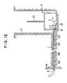
- the augers 6A, 6B, 6C and 6D In withdrawing the augers 6A, 6B, 6C and 6D from the lateral hole L, it is possible to attain the end by pulling them manually by grasping the leading auger 6A when the forward end of the lateral hole L is directed upwardly or when the forward end of the lateral hole L is, as shown in Fig. lE, sticking out of a wall W and the lateral hole L is small in length.
- the augers can be pulled out of the lateral hole L by using a power-operated device.
- the augers 6A, 6B, 6C and 6D can be withdrawn from the lateral hole L by utilizing the lateral hole boring apparatus 2 according to the invention, thereby eliminating the need to use an additional power-operated withdrawing device.
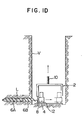
- the auger drive unit 4 of the lateral hole boring apparatus 2 is actuated by the operator positioned on the ground level to rotate the augers in the same direction as when the lateral hole L is formed and the travel device 12 is also actuated to move the auger drive unit 4 rearwardly as indicated by an arrow h in Fig. lE, so as to pull rearwardly all the augers 6A, 6B, 6C and 6D in the lateral hole L and move same a distance corresponding to the length of one auger or the length of the coupling auger 6D, for example.
- the rear end of the coupling auger 6C coupled to the front end of the preceeding coupling auger 6D gripped by the rotary chuck means 8 is gripped by the fixing chuck means 14 as shown in Fig. 1F, and the auger drive unit 4 is actuated to rotate in a direction opposite the direction in which it rotated when it causes the augers to perform a boring operation, and the travel device 12 is actuated to move the auger drive unit 4 in a direction indicated by an arrow i in Fig. 1F or rearwardly in the vertical hole V, so that the preceeding coupling auger 6D gripped by the rotary chuck means 8 is released from threadable engagement with the succeeding coupling auger 6C.
- the coupling auger 6C is released from gripping engagement with the stationary chuck meams 14.
- the lateral hole boring apparatus 2 is moved upwardly to a position above the open end of the vertical hole V as indicated by phantom lines j in Fig. 1F, and the preceeding coupling auger 6D is detached from the rotary chuck means 8.
- the lateral hole boring apparatus 2 is moved downwardly through the vertical hole V to its bottom, and the travel device 12 is actuated to move the auger drive unit 4 forwardly to bring the rotary chuck means 8 into gripping engagement with the rear end of the succeeding coupling auger 6D which serves as a new preceeding auger, and thereafter the augers 6A, 6B and 6C can all be moved rearwardly in the same manner as above-mentioned.
- a pipe p formed of flexible material which is to be laid underground is fitted and secured to the front end of the leading auger 6A as shown in Fig. lE, before the augers 6A, 6B, 6C and 6D are moved rearwardly and withdrawn from the lateral hole L as described hereinabove.
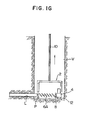
- the pipe P can be inserted in the lateral hole L bored by the augers, as shown in Figs. lF and 1G.
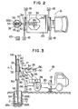
- Figs. 2 and 3 show one example of working machine which provides means for lifting and lowering the lateral hole boring apparatus 2 through the vertical hole V, the working machine being denoted at 16.
- the lateral hole boring apparatus 2 and the working machine 16 provide one example of the entire system for performing the lateral hole boring method according to the invention.
- the machine 16 includes a truck 20 having four outriggers 18.
- the truck 20 supports thereon through a swivel ring 22 a swing 24 having connected thereto a support arm 28 supporting a horizontal cylindrical member 26 at its forward end.
- a horizontal arm 30 Slidably fitted in the horizontal cylindrical member 26 is a horizontal arm 30 which is actuated by a hydraulic cylinder 36 connected through pins 33 and 34 to a bracket 32 secured to the forward end of the arm 30 and the cylindrical member 26, respectively, to move in sliding movement in the direction of an arrow m in Fig. 3.
- a support member 38 which is rectangular in cross section is supported at a top end of the bracket 32 in such a manner that the member 38 can be tilted freely about a pin 40 as indicated by an arrow n in Fig. 3 at least from a position in which it is perpendicular to the ground to a position in which it is parallel to the ground.
- a hydraulic cylinder 46 is connected to bottom pertions of the support member 38 and bracket 32 through pins 42 and 44, respectively, so as to set the support member 38 at a desired tilting position.
- An outer member 48 which is rectangular in cross section is supported in the support member 38 in such a nammer that it is moved in sliding movement by a hydraulic cylinder 54 connected to the members 38 and 48 through pins 50 and 52, respectively.
- An inner member 56 whch is also rectangular in cross section is held in the outer member 48 in such a manner that the inner member 56 can be telescopically moved into and out of the outer member 48 by a hydralic cylinder 62 connected at opposite ends to a lower end of the inner member 56 and an upper end of the outer member 48 through pins 58 and 60, respectively.
- a hydraulic pump which is supported on the truck 20 may be used for supplying hydraulic fluid under pressure to the hydraulic cylinders 36, 54 and 62 and to a drive unit for the swivel ring 22.
- An Operaation device 63 for operating, from the ground level, the hydraulic cylinders 36, 54 and 62 and the swivel ring 22 is located in the vicinity of the vertical hole V as shown in Fig. 2 . Wires and lines connecting the operation device 63 to the hydraulic cylinders 36, 54 and 62 and the drive unit for the swivel ring 22 are not shown.
- the inner member 56 which provides the support means 10 has a flange 64 and a universal joint 66 at its lower end for supporting the laterl hole boring apparatus 2.
- a casing 68A is fitted in a vertical hole, and an additional casing 68B is placed on top of the casing 68A, so as to define the vertical hole V by the two casings 68A and 68B.
- the casing 68A has a bottom wall 68a at the lower end, but the bottom wall 68a may be dispensed with like the other embodiments described later.
- Two guide rails 70a and 70b for guiding the lateral hole boring apparatus 2 when it is moved upwardly and downwardly in the vertical hole V are located on an inner wall surface of the casings 68A and 68B in diametrically opposed positions and extend vertically from top to bottom of the casings 68A and 68B (see Figs. 5 and 6) .
- Stoppers 71a and 71b for holding the lateral hole boring apparatus 2 in a predetermined position at the bottom of the vertical hole V are secured to a lower end of the inner wall surface of the casing 68A (see Fig. 6).
- the hydraulic cylinder 36 is actuated to bring the lateral hole boring apparatus 2 to a position in which it is located substantially in a central portion of the vertical hole V. Then, the hydraulic cylinders 54 and 62 are actuated to move the lateral hole boring apparatus upwardly and downwardly in the vertical hole V. As means for lifting the lateral hole boring apparatus 2, the hydraulic cylinders 54 and 62 may be replaced by a winch or a rack-and pinion arrangement.
- Figs. 4-6 show one embodiment of the lateral hole boring apparatus 2 in conformity with the invention, which comprises support means including a support frame 72 of a substantially gate shape depending from the inner member 56 through the flange 64 and universal joint 66.
- Guide rollers 74a, 74b, 74c and 74d are attached to upper and lower end portions of the support frame 72 in positions in which they can rollingly move along the pair of guide rails 70a and 70b located on the inner wall surface of the casings 68A and 68B.
- a guide frame 76 supporting the lateral hole boring apparatus 2 for movement in a direction perpendicular to the length of the vertical hole V is connected to the support frame 72 through pins 78a and 78b in such a manner that the guide frame 76 is oriented in a direction perpendicular to an imaginary line connecting the guide rails 70a and 70b together toward a slit 68b formed in the casing 68A to allow augers to pass therethrough.
- the guide frame 76 has a pair of guide rails 80a and 80b serving as paths of travel which extend along its length which is perpendicular to the length of the vertical hole V.
- the guide rails 80a and 80b are fitted in grooves formed at outer peripheries of guide rollers 82a, 82b, 82c and 82d secured to a bottom of the auger drive unit 4 in four corners thereof, so that the auger drive unit 4 can be positioned and moved along the guide rails 80a and 80b.
- the travel device 12 for moving the auger drive unit 4 forwardly and rearwardly is constructed as follows.
- the guide frame 76 has an extension 76a which supports a hydraulic motor 84 for moving the auger drive unit 4.
- a chain 90 trained over a sprocket wheel 86 driven for rotation by the hydraulic motor 84 and sprocket wheels 88a and 88b mounted to opposite ends of the extension 76a is connected to a connection 92 located at one side of the auger drive unit 4.
- the auger drive unit 4 can be moved forwardly and rearwardly along the guide rails 80a and 80b.
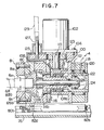
- the auger drive unit 4 and rotary chuck means 8 are constructed as shown in Fig. 7.
- a main body 100 has rotating hydraulic motor 102 secured to its upper portion through a bolt 104, and a rotary member 108 is journalled by a bearing 106 secured to the main body 100 for rotation.
- the hydraulic motor 102 has an output shaft 110 supporting a bevel gear 112 which is kept in meshing engagement with another bevel gear 116 secured to the rotary member 108 through bolts 114a and 114b, and the rotary member 108 supports the rotary chuck means 8 adapted to grip a connection 6a at rear end of one of the augers 6A, 6B, 6C....(hereinafter generally designated by 6).
- the rotary chuck means 8 includes a plurality of gripping claws 8a each secured to a sliding portion 8b formed at its base and slidably fitted in wedge-shaped grooves 108a formed radially in the rotary member 108.
- the rotary chuck means 8 can be moved freely in a direction indicated by an arrow r in Fig. 7 (which is perpendicular to the center of rotation of the rotary member 108).
- clamping means comprising a hydraulic cylinder 122 formed integrally with the rotary member 108 adapted to be supplied with and discharge working fluid through ports l18 and 120, a rod 126 connected to a piston 124 for the hydraulic cylinder 122 and movably extending through a cylindrical bore 108b of the rotary member 108, and a clamp 128 of a conical shape secured to a forward end of the rod 126.
- the clamp 128 is formed with an opening 128a for recieving the connection 6a at the rear end of the auger 6, and wedge-shaped grooves 128b formed along inclined surfaces of the outer peripheries of clamp 128 in positions corresponding to the claws 8a.
- the gripping claws 8a each have a sliding portion 8c which is slidably fitted in one of the wedge-shaped grooves 128b.
- the piston 124, rod 126 and clamp 128 are caused to move in the direction of an arrow t in Fig. 7, and the wedge-shaped grooves 128b are brought into engagement with the sliding portions 8c of the gripping claws 8a, with the result that the gripping claws 8a move in the direction of the arrow r to thereby clamp in place the connection 6a at the rear end of the auger 6 which is inserted in the opening 128a of the clamp 128.
- actuation of the hydraulic motor 102 cuases the rotary member 108 to rotate together with the hydraulic cylinder 122 and rotary chuck means 8 to thereby rotate the auger 6 in a boring direction.
- the gripping claws 8a are caused to move in the direction opposite to the arrow r to allow the auger 6 to be released from the rotary chuck means 8.
- a gear 123 may be attached to the output shaft 110 of the hydraulic motor 102, and the gear 123 being meshed with another gear 125 attached to a shaft 127 to which a flexible shaft 129 rotated by manipulating a handle, not shown, located on the ground level can be connected or disconnected. This allows the auger 6 to be rotated by the operator who manipulates the handle on the ground level, so that the operator is capable of performing a boring operation while ascertaining by the feel of the hand whether there is an obstruct lying ahead of the auger.
- the fixing chuck means 14 for use in attaching and detaching augers 6 is located at one end portion of the guide frame 76 and comprises, as shown in Figs. 8 and 9, a gate-type support frame 130 secured on the guide frame 76, a movable frame 136 movable along guides 132a and 132b located inside the support frame 130 for vertical movement as a hydraulic cylinder 134 disposed at an upper portion of the frame 130 is actuated, and auger gripping claws 142a and 142b supported on left and right sides of a lower end portion of the movable frame 146 for pivotal movement about pins 138a and 138b, respectively, so that the claws 142a and 142b can be opened and closed by the action of a dyraulic cylinder 140 supported by the movable frame 136.
- the hydraulic motors 102 and 84 and hydraulic cylinders 122, 134 and 140 are connected, through their hydraulic hoses not shown, with the operation device 63 (see Fig. 2) and then with a source of hydraulic fluid located on the truck 20, so that their operation can be controlled by the operator positioned on the ground level.
- the hydraulic cylinders 54 and 62 shown in Fig. 3 are contracted to lift the inner member 56, and the apparatus 2 is connected to the inner member 56.
- the auger drive unit 4 is moved to a rearward position, and the rod 126 of the hydraulic cylinder 122 shown in Fig. 7 is brought to an extended position as shown in the figure.
- the leading auger 6A which may be formed of a solid or hollow rod and has a sharp point at the front end and a female type screw connection 6a at the rear end while provided with spiral cutting edges is fitted at the connection 6a in the opening 128a of the clamp 128, and the hydraulic fluid or working fluid is supplied through the port 118 into the rod side chamber of the cylinder 122 to move the piston 124 in the direction of the arrow shown in Fig. 7. This moves the gripping claws 8a in the direction of the arrow r to grip the connection 6a of the leading auger 6A by the gripping claws 8a.
- the angle of swinging movement of the swing 24, the distance covered by the extending horizontal arm 30 and the tilting angle of the outer and inner members 48 and 56 are adjusted to bring the guide rollers 74a, 74b, 74c and 74d of the apparatus 2 into alignment with the guide rails 70a and 70b of the casings 68A and 68B.
- the hydraulic cylinder 54 is extended to fit the guide rollers 74a, 74b, 74c and 74d of the apparatus 2 in the guide rails 70a and 70b, and then the hydraulic cylinders 54 and 62 are extended to move the apparatus 2 downwardly in the vertical hole V until the lower end of the support frame 72 is brought into abutting engagement with the stoppers 71a and 71b at the lower end of the inner wall surface of the casing 68B and stops.
- the fixing chuck means 14 remains in an upper position shown in Fig. 9 so that it may not interfere with the movement of the leading auger 6A.
- the hydraulic motor 84 for moving the drive unit 4 rear is actuated by the operator positioned on the ground level to move the auger drive unit 4 forwardly.
- the hydraulic motor 102 for rotating the auger 6A is actuated, so that the leading auger 6A passes through the slit 68b formed at a lower end of the casing 68A and enters the earth to bore a hole.
- a force exerted by the leading auger 6A produces a reaction which is borne by the wall of the casings 68A and 68B or the vertical hole V through the guide frame 76, support frame 72, guide rollers 74a, 74b, 74c and 74d and guide rails 70a and 70b.
- the working fluid is supplied through the port 120 shown in Fig. 7 into the bottom side chamber of the cylinder 122 to release the rotary chuck means 8 from gripping engagement with the connection 6a of the leading auger 6A and the hydraulic motor 84 is actuated to move the auger drive unit 4 rearwardly 84 until it reaches a rearmost position.
- Soils accumulated at the bottom of the vertical hole V as the auger drive unit 4 moves forwardly as described hereinabove are drawn by suction through a hose connected to a suction pump, not shown, and delivered to the ground level.
- the hydraulic cylinders 54 and 62 are contracted to move the apparatus 2 upwardly above the open end of the vertical hole V, and the coupling auger 6B which may be formed of a solid or hollow rod and has a male screw type connection 6b at the front end and the female screw type connection 6a at the rear end while being provided with spiral cutting edges is gripped at the rear end by the rotary chuck means 8 in the same manner as described by referring to the leading auger 6A. Then, the hydraulic cylinders 54 and 62 are extended to move the apparatus 2 downwardly into the vertical hole V.
- the hydraulic cylinder 134 of the fixing chuck means 14 is extended and the hydraulic cylinder 140 is contracted to cause the claws 142a and 142b to grip the connection 6a at the rear end of the leading auger 6A.
- the hydraulic motor 84 for the auger drive unit 4 is actuated to move the auger drive unit 4 forwardly, and at the same time the hydraulic motor 102 is actuated to bring the connection 6a at the front end of the coupling auger 6B which is the male screw type connection 6a into threadable engagement with the connection 6b at the rear end of the leading auger 6A which is the female screw type connection 6b to thereby couple them together.
- the hydraulic cylinder 140 of the fixing chuck means 14 is extended to release the claws 142a and 142b from gripping engagement with the connection 6a at the rear end of the leading auger 6A, and the hydraulic cylinder 134 is contracted to move- the movable frame 136 upwardly.
- Actuation of the hydraulic motors 84 and 102 causes the drive unit 4 to move forwardly while rotating so as to further bore the lateral hole. The aforesaid operations are repeatedly performed until the legnth of the lateral bore L reaches a predetermined final value.
- the hydraulic motor 84 for the auger drive unit 4 is actuated to move the auger drive unit 4 to the rear position while allowing the hydraulic motor 102 to rotate the auger drive unit 4 in the same direction as it is rotated when a boring operation is performed.
- connection 6a at the rear end of the succeeding auger which may be the auger 6B that is partly exposed in the vertical hole V is gripped by the fixing chuck means 14, and the hydraulic motor 102 is actuated to rotate in a direction opposite the direction in which it rotates when a boring operation is performed to rotate the preceeding auger 6C gripped by the rotary chuck means 8, to thereby release the auger 6C gripped by the rotary chuck means 8 and the auger 6B gripped by the fixing chuck means 14 from the threadable engagement with each other.
- the hydraulic cylinders 54 and 62 are contracted to move the apparatus 2 upwardly above the upper open end of the vertical hole V.
- the rotary chuck means 8 is released from gripping engagement with the auger 6C, and the apparatus 2 is moved downwardly into the vertical hole V again.
- the rotary chuck means 8 grips the connection 6a of the next preceeding auger, which may be the auger 6B, that is exposed in the vertical hole V and the auger 6B is withdrawn from the lateral hole L in the same manner as the auger 6C.
- the preceeding auger 6B is detached from the succeeding auger which may be the auger 6A, and moved upwardly to the ground level.
- the hydraulic motors 102 and 84 and the hydraulic cylinders 122, 134 and 140 can be connected to a source of hydraulic fluid separate from the source of hydraulic fluid on the truck 20.
- the hydraulic devices may be replaced by electric motors as means for supplying drive force to the various parts of the apparatus for carrying the method according to the invention into practice.
- the casings 68A and 68B are used and the stoppers 71a and 71b are provided to the lower portion of the casing 68A to regulate the position of the lateral hole boring apparatus 2 at the bottom of the vertical hole V.
- the stoppers 71a and 71b may be constructed to have their positions adjusted, and the slit 68b for the auger to pass therethrough may be formed to extend through the entire length of the casings 68A and 68B.
- the height of the lateral hole formed by the apparatus 2 may be set at any level as desired.
- the cross-sectional area of the vertical hole V extending from the ground level down into the earth a predetermined depth can be made smaller than has hitherto been the case (when the vertical hole is circular and has a diameter of 50 cm, for example, the cross-sectional area of this vertical hole is about 1/4 that of a conventional vertical hole of about 1 m in diameter).
- the vertical hole V of a predetermined depth from the ground level may not necessarily be cylindrical, and it may be either square or polygonal.
- An increase in the cross-sectional area of the vertical hole V has a disadvantage that the volume of the earth removed by boring increases in proportion to the increase in the cross-sectional area, causing an increase in the damage of the road.
- it offers the advantage that the length of a lateral hole that is formed by one auger 6 can be increased.
- a vertical hole of a circular shape which would enjoy this advantage while minimizing the damage to the road to such an extent that no temporary repair is necessary would preferably have a diameter smaller than 70 cm and greater than 40 cm.
- the diameter range would be 45-60 cm which would make it impossible for the operator to do work while stooping down.
- the dimensions of the hole as viewed from different directions would preferably be similar to those of the circular vertical hole.
- the dimension of the hole as measured in a direction in which the auger is moved forwardly and rearwardly is greater than 70 cm and its dimension as measured in a direction perpendicular to the direction in which the auger is moved forwardly and backwardly is smaller than 40 cm
- the distance covered by the movement of the auger could be increased while reducing the cross-sectional area of the vertical hole.
- the vertical hole V may be tilting with respect to the ground.
- a second embodiment of the lateral hole boring method in conformity with the invention will now be described as being applied to the boring of a lateral hole for laying a gas service pipe to be connected to an existing gas main.
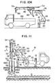
- the second embodiment of the lateral hole boring method includes operation steps which are followed substantially in the order shown in Figs. 10A - 10K.
- the operation for providing the vertical hole V and the operation for backfilling the vertical hole after boring of the lateral hole are conducted by using the machine shown in Figs. 2 and 3 and used for lifting and lowering the lateral hole boring apparatus 2 in the first embodiment.
- a hole saw 150 shown in Fig. 10A is connected to the flange 64 at the lower end of the inner member 56 of the machine shown in Figs. 2 and 3 to cut a surface layer S of the ground in a circle of about 50 cm in diameter and bore a hole in a macadam layer R as a preliminary step.
- the hole saw 150 includes a drum-shaped cutter 160 with bits 158 which is rotated through a gearing 156 by a hydraulic motor 164 while supplying water through a water injector 152 to a portion of the ground which is being cut.
- a probing instrument and a metal sensor are used to detect the position in which boring is to be performed.
- the hydraulic cylinders 36, 46, 54 and 62 are rendered operative to bring the hole saw 150 into index with a point on the surface of the road which is located above the existing main Q under the ground.
- the angle of the inner member 56 can be adjusted by manipulating the hydraulic cylinder 46 so as to bring the entire surface of the cutter 158 of the bit 160 into contact with the surface of the road even if the road is sloping to thereby perform cutting satisfactorily.
- a bucket 164 having a hydraulic cylinder 162 for opening and closing the bucket 164 is connected to the flange 64 of the inner member 56 to remove the earth inside and below the casing 68A and store same in a box 166 shown in Fig. 10C which is located in the vicinity of the site of excavation.
- a lid 168 is placed on the casing 68A as shown in Fig. 10D and the hydraulic cylinder 54 is extended to force the casing 68A to move downwardly through the bucket 164.
- Fig. 10D a lid 168 is placed on the casing 68A as shown in Fig. 10D and the hydraulic cylinder 54 is extended to force the casing 68A to move downwardly through the bucket 164.
- the casing 68B is placed on the casing 68A, and bolts 172a and 172b inserted in connections 170a and 170b secured to the upper casing 68B are threadably fitted in openings 174a and 174b formed in the lower casing 68A to connect the two casings 68A and 68B together.
- the pair of guide rails 70a and 70b are located on the inner wall surface of the casings 68A and 68B and extending vertically in positions diametrically opposed to each other as described hereinabove for guiding the movement of the lateral hole boring apparatus 2 into and out of the vertical hole V.
- a boss is formed at the upper edge of the lower easing 68A, and the boss is adapted to be fitted in an aperture fromed in the lower edge portion of the upper casing 68B so as to bring the guide rails 70a and 70b of the upper and lower casings 68B and 68A into alignment with each other.
- a manually-operated excavator 176 is used to remove earth carefully to expose both sides of the existing main Q without damaging same.
- Figs. 12 and 13 show the vertical hole V formed as the result of the excavation work described hereinabove.
- the vertical hole V is formed by forcing the casings 68A and 68B into the ground.
- this depth is not restrictive, and only one casing or more than three casings may be used for forming a vertical hole.
- the casings maybe of the same length.
- the number of casings used for forming a vertical hole of a given depth can be reduced if casings of different lengths are prepared and used in a suitable combination.
- a boring tool such as a screw auger 6A
- a boring tool is attached to the lateral hole boring apparatus 2 to bore a lateral hole L for laying a new pipe P.
- the lateral hole boring apparatus 2 has been described by referring to Figs. 4-9 showing the first embodiment.
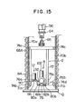
- the apparatus 2 will further be illustrated in Figs. 14 and 15 in conjunction with the vertical hole V.
- the lateral hole boring apparatus 2 show in Figs. 13 and 14 bores the lateral hole L in the same manner as described by referring to Figs. 4-9 showing the first embodiment.
- the flexible shaft 129 for transmitting power may be extended through the outer member 48 and inner member 56, and a handle 180 may be mounted to its upper end as shown in Fig. 10G while its lower end is releasably engages the shaft 127 of the gear 125 meshing with the gear 123 mounted to the output shaft of the hydraulic motor 102 for rotating the augers shown in Fig. 7.
- the augers 6A and 6B can be not only automatically rotated but also manually actuated to bore the lateral hole L.
- the new pipe P formed of a synthetic resinous and flexible material which is to be laid in the lateral hole L is inserted from a pit H formed in the premises of a household to which town gas is to be supplied and coupled to a forward end of the leading auger 6A. Then, the augers 6A and 6B are moved rearwardly from the lateral hole L to allow the new pipe P to be laid in the lateral hole L. After the new pipe P is thus laid in the lateral hole L, it is connected to the existing main Q. The connection is effected by using a tool that can be manipulated by the operator positioned on the ground level. The detailed description of the operation shall be omitted because it does not constitute a part of the invention.
- soil 182 is thrown into the casings 68A and 68B in volumes large enough to fill the casings 68A and 68B partly and compacted by using a suitable tool, such as a manually-operated member 184. Then, the casing 68A or 68B is lifted, as shown in Fig. 10J, by using a hanger 186 having a hook attached to the outer member 48, a rod 188 connected to the casing 68A or 68B and a rope 190. Thereafter, the soil in the casings 68A and 68B is compacted again.
- the outer member 48 is brought to a substantially horizontal position and the swing 24 and hydraulic cylinders 36 and 54 are actuated to load, by utilizing the anger 186, a truck 192 with the earth removed from under the ground and tools used to perform the hole-boring and pipe-laying operations.
- the lateral hole L By boring the lateral hole L as described hereinabove, it is possible to reduce the cross-sectional area of the vertical hole V used to have access to the existing main Q from the surface of the ground, as compared with the cross-sectional area of a conventional vertical hole. Additionally, the casings 68A and 68B are force-fitted into the ground to form the vetical hole V without disintegration of the vertical hole V, and the need to dig a ditch across the street is eliminated. This makes it possible to perform a full-scale repair upon completion of the operation of laying the new pipe P without failing to keep the road in good condition. This is conducive to a marked reduction in the period of time required for laying the new pipe P by boring the lateral hole L, because the operation can be finished in one day.
- the earth removed by the excavation work is greatly reduced in volume, and the elimination of the need to perform temporary repair greatly reduces workforce required for the operation.
- the share of expenses for laying the new pipe P in total expenses for performing the civil engineering operations can be reduced from about 80% to about 50%, and the expenses for laying the new pipe P can be reduced by about 60%.
- the second embodiment of the invention has been described in conjunction with the operation of laying a new pipe to be connected to an existing main to supply town gas to a property, as shown in Figs. l0A -10K and 11-15.
- this embodiment can be carried into practice not only in boring a lateral hole for laying a new pipe to be connected to an existing main for supplying city gas but also in boring a lateral hole for laying a new pipe to be connected to an existing water or other fluid supply line or for laying a new tube to be connected to an existing tube for housing electrical cables or communications lines.
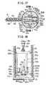
- Figs. 16-21 show a second embodiment of the apparatus for boring a lateral hole suitable for carrying the method of boring a lateral hole according to the invention into practice.
- parts similar to those shown in Figs. 1-15 are designated by like reference characters.
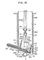
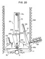
- the lateral hole boring apparatus shown in Figs. 16-21 is generally designated by the reference numeral 2A and distinct from the lateral hole boring apparatus 2 described by referring to Figs. 4-9 in the manner in which the guide frame 76 is connected to the support frame 72.
- the guide frame 76 has attached to one side a connecting member 76b to which a connecting pin 200 is secured at one end.
- the connecting pin 200 rotatably extends through one vertical member 72a of the support frame 72 and has secured to an opposite end thereof an adjusting plate 204 formed with an arcuate slot 202 as shown in Fig. 20.
- Fixing bolts 206a and 206b extend through the arcuate slot 202 and threadably engage threaded openings formed in a receiver plate, not shown, secured to the vertical member 72a.
- the guide frame 76 can be moved in pivotal movement about the pin 200 by loosening the fixing bolts 206a and 206b, and the guide frame 76 can be fixed to the support frame 72 by tightening the fixing bolts 206a and 206b.
- the tilting angle of the guide frame 76 is preferably in the range between the angle at which the guide frame 76 or the augers 6A, 6B and 6C are horizontally disposed and the angles of about 15-20 degrees at which the leading end of the auger 6A is disposed with respect to the horizontal.
- lateral hole boring apparatus 2A Other parts of the lateral hole boring apparatus 2A are substantially similar to the corresponding parts of the lateral hole boring apparatus 2 shown in Fig. 4-9.
- the guide frame 76 can be tilted with respect to the support frame 72 in the lateral hole boring apparatus 2A.
- This feature offers the following advantages. By tilting the guide frame 76 as shown in Figs. 19 and 20, it is possible to bore a tilting lateral hole Lo which is inclined with respect to the horizontal in such a manner that an end of the lateral hole Lo disposed in the premises of a property to which water or town gas is intended to be supplied is located at a higher level than an opposite end, as shown in Fig. 21.
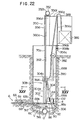
- Figs. 22-25 show one example of the lateral hole boring system comprising the other embodiments of the lateral hole boring apparatus and the lifting and lowering means suitable for carrying the lateral hole boring method into practice.
- the lateral hole boring apparatus generally designated by the reference numeral 302 comprises an elevatory frame 308 including a gate type support frame 304 and a guide frame 306 secured to the suppot frame 304.
- the support frame 304 includes left and right posts 304a and 304b having guide rollers 310a, 310b, 310c and 310d secured to upper and lower portions thereof for rolling movement along the guide rails 70a and 70b secured to the inner wall surface of the casings 68A and 68B in diametrically opposed positions and extending vertically.
- the guide frame 306 secured to the support frame 304 supports the auger drive unit 4 for movement therealong, as is the case with the guide frame 76 described by referring to Figs. 4-6.
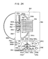
- fixing chuck means 312 for detaching augers which comprises, as shown in Fig. 25, a pair of hydraulic cylinders 314 and 316 located on the left and right sides and secured to the guide frame 306 through pins, a pair of links 326 and 328 connected to the guide frame 306 for pivotal movement about pins 318 and 320 and connected at one end thereof to piston rods of the hydraulic cylinders 314 and 316 through pins 322 and 324, respectively, and claw holders 338 and 340 secured to an opposite end of the links 326 and 328 through pins 330 and 332, respectively, and having at a forward end claws 334 and 336 for gripping the connection 6a of the auger 6.
- the connection 6a can be gripped and released by the claws 334 and 336.
- lifting and lowering means 350 is used for moving the lateral hole boring apparatus 302 upwardly and downwardly.
- the means 350 comprises, as shown in Fig. 22, a frame structure 356 supporting a winch 352 and a control panel 354, the frame structure 356 including a main frame body 356a of substantially semi-cylindrical configuration having a semi-circular flange portion 356b at its lower end.
- the frame structure 356 is secured to the casing 68B by placing the flange portion 356b on top of the casing 68B and fixing a lower end portion 356c by screws 358a, 358b and 358c to the side of an upper portion of the casing 68B.
- the frame structure 356 also includes vertical frames 356d and 356e attached to an inner surface of the main frame body 356a on left and right sides and supporting guide rails 360a and 360b which are adapted to be connected to the guide rails 70a and 70b of the casing 68B.
- a support member 356f supporting the winch 352 is interposed between upper ends of the vertical members 356d and 356e.
- the winch 352 comprises a hydraulic motor 352a and two drums 352b and 352c.
- a wire rope 362 which is wound on the drums 352b and 352c and payed out of them is trained over a sieve 364 (see Fig. 22) attached to a central portion of an upper member 304c of the support frame 304.
- the hydraulic motor 352a is rotated in the normal and reverse directions, the lateral hole boring apparatus 302 can be moved upwardly and downwardly.
- the control panel 354 mounts thereon switches 366A and 366B for turning on and off a power source, an operation lever 368 for controlling the flow rate and direction of flow of a hydraulic fluid or working fluid to the travel hydraulic motor 84, an oil pressure gauge 370 for indicating the pressure of the working fluid flowing to the travel hydrauylic motor 84, push-button switches 372A and 372B for actuating the hydraulic cylinders 314 and 316 of the stationary chuck means 312 to move the claws 334 and 336 between an open position and a closed position, push-button switches 374A, 374B and 374C for giving instructions to the travel hydraulic motor 84 to rotate the auger 6 counterclockwise and clockwise and stop its rotation, respectively, an oil pressure gauge 374D for indicating the pressure of the working fluid flowing to the hydraulic motor 102, a variable knob 374E for regulating the flow rate of the working fluid to the travel hydraulic motor 84, push-botton switches 376A and 376B for moving
- hydraulic fluid hoses 380 and 382 and a cable 384 are connected at one end thereof to a hydraulic pump, a hydraulic fluid tank and a power source (all not shown) mounted on a working vehicle, not shown, respectively, and at the other end thereof to the control panel 354.
- the hydraulic fluid hoses 380 and 382 provide branch channels for hydraulic fluid handling devices, such as valves in the control panel 354, operated by the aforesaid push-button switches, and for hydraulic fluid handling devices 386 (including valves not mounted in the control panel 354) mounted on a rear end of the frame 356 as shown in Fig. 22.
- a hydraulic fluid hose group 388 comprising a plurality of pairs of hydraulic fluid hoses, each pair constituting one of the branch channel, is connected to drive means of the aforesaid various devices, such as the hydraulic cylinders 314 and 316 of the fixing chuck means 312, the drive of the rotary chuck means 8 and the hydraulic motors 84 and 102.
- an L-shaped member 390 is attached to the upper member 304c of the support frame 304, and a roller 392 for supporting the hydraulic fluid hose group 388 is located on top of the L-shaped member 390 to prevent the hydraulic fluid hose group 388 from becoming loose.
- a portion of the hydraluic fluid hose group 388 located between the upper member 304c of the frame 304 and the main frame body 356a becomes substantially taut when the lateral hole boring apparatus 302 is disposed in the lowermost position as shown in Fig. 22.
- the hydraulic fluid hose group 388 becomes slightly loose when the apparatus 302 moves upwardly, but this does not interfere with the upard movement of the apparatus 302.
- the roller 392 extends through an opening 356g in the upper portion of the main frame body 356a above the frame structure 356 to push the hydraulic fluid hose group 388 upwardly to tighten same.
- the frame structure 356 is open at the front and its height from the upper end of the casing 68B is such that, when the apparatus 302 is moved to the uppermost position indicated by imaginary lines in Fig. 23, the rotary chuck means 8 is located above the casing 68B.
- the apparatus 302 When the lateral hole boring apparatus 302 is used to bore a lateral hole, the apparatus 302 is moved to the uppermost position indicated by the imaginary lines in Fig. 23 and the auger drive unit 4 is moved to its rearward position. After the leading auger 6A is attached to the rotary chuck means 8, the winch 352 is actuated to pay out the wire rope 362 to move the apparatus 302 downwardly to a solid-line position in which stoppers 394a and 394b located at the lower end portions of the guide rails 70a and 70b are broght into locking engagement with locking members 396a and 396b secured to the support frame 304, respectively. Thereafter, the lateral hole L is formed by the lateral hole boring apparatus 302 in the same manner as described previously by referring to the drawings while moving the apparatus 302 upwardly and downwardly by the lifting and lowering means 350 to attach and detach the augers 6.
- the lateral hole boring operation can be performed by the operator who manipulates the switches or levers on the control panel 354 while looking into the vertical hole V.
- control panel 354 and hydraulic fluid handling devices 386 have been described as being located at the frame 356 on the casing 68B. However, this is not restrictive and they may be located in the vicinity of the casing 68B.
- the hydraulic and electric power sources may be formed into a unitary structure with the control panel 354 or constitute entitles separate therefrom anbd located on the ground level.
- the drive means may be electrically operated.
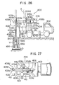
- the working machine 400 comprises a swing support 404 located on a truck 402 and comprising a cylindrical support 404a, an annular swing member 404b located on the cylindrical support 404a and a hydraulic motor 404c for moving a swinging side of the annular swing member 404b in swinging movement.
- a horizontal telescopic arm 406 including an outer arm 406a of substantially cylindrical configuration secured to the swinging side of the annular swinging member 404b, and an inner arm 406b of large length slidably fitted in the outer arm 406a.
- a pinion 406d rotated by a hydraulic motor 406c supported by the outer arm 406a is maintained in meshing engagement with a rack 406e supported by the inner arm 406b. Actuation of the hydraulic motor 406c causes the inner arm 406b to move inside the outer arm 406a.
- the horizontal telescopic arm 406 can be moved rearwardly and through an angle 8' in swinging movement as shown in Fig. 27 by the annular swing member 404b.
- a vertical telescopic arm 408 Connected to a forward end of the inner arm 406b is a vertical telescopic arm 408 including an outer arm 408a of substantially cylindrical configuration secured to the inner arm 406b and extending vertically, an intermediate arm 408b of substantially cylindrical configuration slidingly fitted in the outer arm 408a and an inner arm 408c of substantially cylindrical configuration slidingly fitted in the intermediate arm 408b.
- Hydraulic motors 408f and 408g having pinions 408d and 408e are connected to lower end portions of the outer arm 408a and intermediate arm 408b, respectively, and racks 408h and 408i meshing with the pinions 408d and 408e are secured to the intermediate arm 408b and inner arm 408c, respectively.
- Actuation of the hydraulic motors 408f and 408g causes the intermediate arm 408b and inner arm 408c to move verticlaly.
- the bucket 164 or the cutter 158 of the rotary type boring machine for boring a hole in an asphalt layer of a road is respectively mounted at a lower end of the inner arm 408c.
- the truck 402 has a space 410 rearwardly of the swing support 404 for mounting the casing 68, lateral hole boring appartus 302, bucket 164, rotary boring machine 158 for boring a hole in the asphalt layer of the road and other boring machine.
- the horizontal telescopic arm 406 and vertical telescopic arm 408 are contracted as indicated at A in Fig. 26 and the swing motor 404c is actuated to pivotally move the horizontal telescopic arm 406 to bring the vertical telescopic arm 408 to a position above the desired boring machine. Then, the boring machine is attached to the vertical telescopic arm 408 or suspended therefrom by a hook and moved to a position in which a vertical hole V is to be formed.
- the maximum swinging angle of the anunular swing member 404 in its leftward and rightward movement is small as indicated at 8 in Fig. 27.
- a control panel for operating the hydraulic motor 404c for driving the annular swing member 404b, the hydraulic motors 406c, 408f and 408g for driving the horizontal and vertical telescopic arms 406 and 408, the bucket 164, the cutter 158 of the boring machine for boring a hole in the asphalt layer and the actuator of the lateral hole boring apparatus 302 may be located, as indicated at 411 in Fig. 27, in the vicinity of the vertical hole V to be formed, or fixed to the casing 68B as is the case with the embodiment shown in Figs. 22-25 after the vertical hole V has been formed, so that the operation can be performed by a single operator while looking into the vertical hole V.
- the swing support 404 may be formed as a telescopic structure. More specifically, the cylindrical support 404a secured to the truck 402 serves as an outer member, and an inner member 404e that can be moved in elevatory movement in a stroke S by a hydraulic cylinder 404d is fitted in the cylindrical support 404a for telescopic movement.
- the horizontal telescopic arm 406 is mounted on the inner member 404e through the annular swing member 404b.
- the horizontal telescopic arm 406 can be moved to a higher level by actuating the hydraulic cylinder 404d during operations to thereby enable the boring machine attaching and detaching operation to be performed at a higher level. This facilitates the opration.
- the hydraulic cylinder 404d is actuated to move the horizontal telescopic arm 406 to a lower level to thereby reduce the overall height of the truck 402.
- the swing support 404 may be constructed to be removably mounted to an ordinary truck.
- a vertical hole formed beforehand to a predetermined depth in preparation for boring a lateral hole can be reduced in cross-sectional area as compared with vertical holes formed hitherto in boring vertical holes by the prior art.
- the vertical hole necessary for carrying the lateral hole boring method into practice only has to be large enough to move the lateral hole boring apparatus upwardly and downwardly therein. This greatly reduces the volume of earth removed from under the ground, and makes it possible to shorten the period of time and cut the expenses and workforce necessary for boring a lateral hole.
- the use of a vertical hole of a small cross-sectional area makes it possible to minimize road traffic obstruction.
- the invention eliminates the need for the operator to enter the vertical hole, enabling a lateral hole boring operation to be performed without any danger.
- the augers used for boring a lateral hole can be detached one from another and withdrawn from the hole to be lifted to the ground by the operator who operates the apparatus on the ground levle. This eliminates the need to use an additional device for withdrawing a series of augers of large total length and makes it possible to insert a pipe into the lateral hole simultaneously as the augers are withdrawn from the lateral hole.
- the invention eliminates the need to dig a ditch which has been dug for laying a pipe by an open-cut process in the prior art.
- the invention offers the additional advantage that, besides being able to reduce the cross-sectional area of the vertical hole, the elimination of the need to dig a ditch further reduces expenses and workforce and shortens the period of time for performing a lateral hole boring operation while minimizing road traffic obstruction.
- casings may be forced into the vertical hole in performing an operaiton. This is conductive to prevention of the disintegration of the vertical hole and enables positioning of the lateral hole boring apparatus to be readily effected.
- the guide frame supporting the auger drive unit of the lateral hole boring apparatus can be connected to the support frame in such a manner that the tilting angle of the guide frame can be adjusted as desired with respect to the support frame.
- This makes it possible to bore a lateral hole disposed at a desired angle with respect to the horizontal.
- This feature makes it possible to reduce the dimensions of a hole formed at the end of the lateral hole located in the premises of a property to which gas or water is intended to be supplied and to bypass any obstacle that might lay ahead of the lateral hole to be formed by the method according to the invention.
- the size of the vertical hole couold not be much reduced because the space for lifting the augers would be required in addition to the space for accommodating hydraulic fluid hoses (cables when electrical equipment is used) connected to the hydraulic machines used for actuating the lateral hole boring apparatus and elevatory means for the auger.
- the need to provide space for moving the auger upwardly and downwardly in the vertical hole is eliminated because the auger is coupled or uncoupled to the auger drive unit on the ground level, thereby enabling the size of the vertical hole to be reduced and the volume of the earth removed from under the ground to be minimized.
- connection of the leading auger is gripped by the fixing chuck means and the connection of the trailing auger is brought into threadable engagement with the connection of the leading auger. This enables the trailing auger to be smoothly coupled to the leading auger because centering can be positively effected.
Landscapes
- Engineering & Computer Science (AREA)
- Life Sciences & Earth Sciences (AREA)
- Geology (AREA)
- Mining & Mineral Resources (AREA)
- Mechanical Engineering (AREA)
- Physics & Mathematics (AREA)
- Environmental & Geological Engineering (AREA)
- Fluid Mechanics (AREA)
- General Life Sciences & Earth Sciences (AREA)
- Geochemistry & Mineralogy (AREA)
- Earth Drilling (AREA)
Applications Claiming Priority (10)
| Application Number | Priority Date | Filing Date | Title |
|---|---|---|---|
| JP13709484A JPS6117690A (ja) | 1984-07-04 | 1984-07-04 | 横穴掘削工法 |
| JP137097/84 | 1984-07-04 | ||
| JP13709684A JPS6117691A (ja) | 1984-07-04 | 1984-07-04 | 横穴掘削装置 |
| JP13709584A JPS6117695A (ja) | 1984-07-04 | 1984-07-04 | 管埋設用横穴掘削工法 |
| JP137096/84 | 1984-07-04 | ||
| JP100010/84U | 1984-07-04 | ||
| JP13709784A JPS6117692A (ja) | 1984-07-04 | 1984-07-04 | 横穴掘削装置 |
| JP137094/84 | 1984-07-04 | ||
| JP137095/84 | 1984-07-04 | ||
| JP10001084U JPS6119092U (ja) | 1984-07-04 | 1984-07-04 | 横穴掘削用掘削具着脱装置 |
Publications (2)
| Publication Number | Publication Date |
|---|---|
| EP0167979A1 true EP0167979A1 (fr) | 1986-01-15 |
| EP0167979B1 EP0167979B1 (fr) | 1989-03-15 |
Family
ID=27525985
Family Applications (1)
| Application Number | Title | Priority Date | Filing Date |
|---|---|---|---|
| EP85108240A Expired EP0167979B1 (fr) | 1984-07-04 | 1985-07-03 | Méthode et dispositif pour le forage latéral |
Country Status (3)
| Country | Link |
|---|---|
| US (1) | US4691788A (fr) |
| EP (1) | EP0167979B1 (fr) |
| DE (1) | DE3568818D1 (fr) |
Cited By (4)
| Publication number | Priority date | Publication date | Assignee | Title |
|---|---|---|---|---|
| US4691788A (en) * | 1984-07-04 | 1987-09-08 | Hitachi Construction Machinery Co., Ltd. | Lateral hole boring method and apparatus |
| US7316280B2 (en) | 2001-07-12 | 2008-01-08 | Tracto-Technik Gmbh | Method for producing earth boreholes |
| WO2011120692A3 (fr) * | 2010-03-31 | 2013-01-03 | Tracto-Technik Gmbh & Co. Kg | Procédé de réalisation d'un forage horizontal dans le sol et dispositif de forage horizontal |
| KR101239524B1 (ko) * | 2008-05-15 | 2013-03-05 | 퀄컴 인코포레이티드 | 고속 저전력 래치 |
Families Citing this family (15)
| Publication number | Priority date | Publication date | Assignee | Title |
|---|---|---|---|---|
| US5553680A (en) * | 1995-01-31 | 1996-09-10 | Hathaway; Michael D. | Horizontal drilling apparatus |
| US5810101A (en) * | 1996-09-11 | 1998-09-22 | Engineering Crossing Systems, (Partnership) | Horizontal drilling machine |
| FR2765827B1 (fr) * | 1997-07-08 | 1999-09-17 | Jean Pierre Brulhart | Machine de carottage |
| US6732816B2 (en) * | 2000-05-03 | 2004-05-11 | Lattice Intellectual Property Limited | Method of forming a trenchless flowline |
| US6464022B1 (en) | 2000-07-24 | 2002-10-15 | Gerard R. O'Brien | Mobile horizontal directional boring apparatus and method for use in boring from existing utility manholes |
| US7631708B2 (en) * | 2000-09-18 | 2009-12-15 | Robert Billingsley | Method and apparatus for horizontal drilling and oil recovery |
| US20020062993A1 (en) * | 2000-09-18 | 2002-05-30 | Robert Billingsley | Method apparatus for horizontal drilling and oil recovery |
| US20050167160A1 (en) * | 2001-09-18 | 2005-08-04 | Robert Billingsley | Method and apparatus for horizontal drilling and oil recovery |
| DE10159712B4 (de) * | 2001-07-12 | 2004-12-02 | Tracto-Technik Gmbh | Bohrgerät und Verfahren zum Herstellen von Erdbohrungen |
| DE102008006392A1 (de) * | 2008-01-28 | 2009-07-30 | Herrenknecht Vertical Gmbh | Verfahren und Vorrichtung zum Erstellen einer Tiefbohrung |
| DE102011101442B4 (de) | 2011-05-12 | 2023-08-31 | Tracto-Technik Gmbh & Co. Kg | "Verfahren zum Durchführen einer Erdbohrung von einer Startbaugrube mit einer Erdrakete und Bohrsystem mit einer Lafette für eine Erdrakete zur Positionierung der Erdrakete in einer Startbaugrube zur Durchführung einer Erdbohrung in einer vorbestimmten Tiefe" |
| FI3752702T3 (fi) * | 2018-02-13 | 2023-02-20 | Järjestelmiä ja menetelmiä maanalaisen putken asennukseen | |
| CN110616729B (zh) * | 2019-09-29 | 2021-03-16 | 浙江海洋大学 | 一种边坡高层建筑深基坑变形控制的施工方法 |
| AU2023208536A1 (en) * | 2022-01-19 | 2024-08-29 | Havailon Group | Grade guided trackless horizontal boring rig |
| US11959338B2 (en) | 2022-09-15 | 2024-04-16 | Arcbyt, Inc. | Multi-tool boring systems and methods of operating such systems |
Citations (7)
| Publication number | Priority date | Publication date | Assignee | Title |
|---|---|---|---|---|
| GB153931A (en) * | 1919-06-17 | 1920-11-17 | Arthur Rivington Mangnall | Improvements in earth boring machines |
| DE448111C (de) * | 1925-11-06 | 1927-08-09 | Walter Brechtel | Traggeruest fuer die Belastung der Bohrrohre zum Bohren von Brunnen |
| US4226288A (en) * | 1978-05-05 | 1980-10-07 | California Institute Of Technology | Side hole drilling in boreholes |
| US4317492A (en) * | 1980-02-26 | 1982-03-02 | The Curators Of The University Of Missouri | Method and apparatus for drilling horizontal holes in geological structures from a vertical bore |
| US4365676A (en) * | 1980-08-25 | 1982-12-28 | Varco International, Inc. | Method and apparatus for drilling laterally from a well bore |
| DE3139655A1 (de) * | 1981-10-06 | 1983-04-21 | Gewerkschaft Eisenhütte Westfalia, 4670 Lünen | Rohrvorpresseinrichtung |
| US4417628A (en) * | 1981-10-05 | 1983-11-29 | Gessner Richard W | Earth boring apparatus |
Family Cites Families (11)
| Publication number | Priority date | Publication date | Assignee | Title |
|---|---|---|---|---|
| US1362775A (en) * | 1920-04-10 | 1920-12-21 | Charles A Bunker | Material excavator and separator for oil-wells |
| US1593629A (en) * | 1925-09-11 | 1926-07-27 | Ingersoll Rand Co | Equalizer for rock drills |
| US1932068A (en) * | 1930-07-22 | 1933-10-24 | Hydrauger Corp Ltd | Earth boring apparatus |
| US2165666A (en) * | 1937-06-24 | 1939-07-11 | James Hailey | Horizontal drilling machine |
| US2588068A (en) * | 1948-01-09 | 1952-03-04 | Cons Edison Co New York Inc | Drilling apparatus |
| US2752122A (en) * | 1954-10-21 | 1956-06-26 | Sigmon | Tractor driven boring implement |
| US2889137A (en) * | 1958-02-13 | 1959-06-02 | Robert K Walker | Apparatus for drilling laterals from well shafts |
| US3282356A (en) * | 1963-12-02 | 1966-11-01 | Ingersoll Rand Co | Drilling device |
| US4222687A (en) * | 1978-06-12 | 1980-09-16 | Williams Richard Lee | Apparatus for boring sewer pipe opening in manhole base |
| FR2527679B1 (fr) * | 1982-05-27 | 1987-04-24 | Delbarre Jean | Procede et dispositif pour le forage du sol |
| DE3568818D1 (en) * | 1984-07-04 | 1989-04-20 | Hitachi Construction Machinery | Lateral hole boring method and apparatus |
-
1985
- 1985-07-03 DE DE8585108240T patent/DE3568818D1/de not_active Expired
- 1985-07-03 US US06/751,735 patent/US4691788A/en not_active Expired - Fee Related
- 1985-07-03 EP EP85108240A patent/EP0167979B1/fr not_active Expired
Patent Citations (7)
| Publication number | Priority date | Publication date | Assignee | Title |
|---|---|---|---|---|
| GB153931A (en) * | 1919-06-17 | 1920-11-17 | Arthur Rivington Mangnall | Improvements in earth boring machines |
| DE448111C (de) * | 1925-11-06 | 1927-08-09 | Walter Brechtel | Traggeruest fuer die Belastung der Bohrrohre zum Bohren von Brunnen |
| US4226288A (en) * | 1978-05-05 | 1980-10-07 | California Institute Of Technology | Side hole drilling in boreholes |
| US4317492A (en) * | 1980-02-26 | 1982-03-02 | The Curators Of The University Of Missouri | Method and apparatus for drilling horizontal holes in geological structures from a vertical bore |
| US4365676A (en) * | 1980-08-25 | 1982-12-28 | Varco International, Inc. | Method and apparatus for drilling laterally from a well bore |
| US4417628A (en) * | 1981-10-05 | 1983-11-29 | Gessner Richard W | Earth boring apparatus |
| DE3139655A1 (de) * | 1981-10-06 | 1983-04-21 | Gewerkschaft Eisenhütte Westfalia, 4670 Lünen | Rohrvorpresseinrichtung |
Non-Patent Citations (1)
| Title |
|---|
| BELL LABORATORIES RECORD, vol. 45, no. 3, March 1967, pages 70-74, Murray Hill, GB; D. MILSARK: "Burying wire and cable under obstructions" * |
Cited By (6)
| Publication number | Priority date | Publication date | Assignee | Title |
|---|---|---|---|---|
| US4691788A (en) * | 1984-07-04 | 1987-09-08 | Hitachi Construction Machinery Co., Ltd. | Lateral hole boring method and apparatus |
| US7316280B2 (en) | 2001-07-12 | 2008-01-08 | Tracto-Technik Gmbh | Method for producing earth boreholes |
| KR101239524B1 (ko) * | 2008-05-15 | 2013-03-05 | 퀄컴 인코포레이티드 | 고속 저전력 래치 |
| WO2011120692A3 (fr) * | 2010-03-31 | 2013-01-03 | Tracto-Technik Gmbh & Co. Kg | Procédé de réalisation d'un forage horizontal dans le sol et dispositif de forage horizontal |
| EP2728104A1 (fr) * | 2010-03-31 | 2014-05-07 | Tracto-Technik GmbH & Co.KG | Procédé de réalisation d'un forage horizontal dans le sol et dispositif de forage horizontal |
| US9523240B2 (en) | 2010-03-31 | 2016-12-20 | Tracto-Technik Gmbh & Co. Kg | Method for producing a horizontal bore in the ground and horizontal drilling device |
Also Published As
| Publication number | Publication date |
|---|---|
| US4691788A (en) | 1987-09-08 |
| DE3568818D1 (en) | 1989-04-20 |
| EP0167979B1 (fr) | 1989-03-15 |
Similar Documents
| Publication | Publication Date | Title |
|---|---|---|
| EP0167979B1 (fr) | Méthode et dispositif pour le forage latéral | |
| US4475604A (en) | Mobile machine for subterranean installation of piping and the like | |
| US4024721A (en) | Method and apparatus for laying pipes in the ground | |
| US4542796A (en) | Process and device for drilling the soil | |
| AU691712B2 (en) | Drilling and pipe laying unit | |
| US5584351A (en) | Drilling machine and method of horizontal boring | |
| US6068426A (en) | Method of connecting conduits | |
| US5873421A (en) | Tool for installing a pipeline under a structure | |
| CN115450275A (zh) | 一种电缆窄沟槽用链条式开槽机 | |
| CN114876363A (zh) | 一种防回填地基打桩钻孔设备 | |
| EP1407112B1 (fr) | Procede permettant de realiser des sondages | |
| CA2235196C (fr) | Methode d'echantillonnage du sol a partir d'un trou de forage horizontal | |
| JPH0344871Y2 (fr) | ||
| US3612194A (en) | Earth-boring machine | |
| US3610345A (en) | Earth boring machine carriage with detachable pusher ring and power frames | |
| JP2592615Y2 (ja) | 二重管取付装置 | |
| JPS6117695A (ja) | 管埋設用横穴掘削工法 | |
| CA2235204C (fr) | Sonde pedologique servant a prendre de multiples echantillons du sol a partir de trous de forage horizontaux | |
| JPS6117691A (ja) | 横穴掘削装置 | |
| CN111156020B (zh) | 一种下水管道非挖掘维修用设备及其施工方法 | |
| CN210317159U (zh) | 一种建筑基础工程用旋转挤土桩机 | |
| JPS644948Y2 (fr) | ||
| JPH0513829Y2 (fr) | ||
| JPS6311786A (ja) | 地下配管埋設用横穴掘削工法 | |
| CN121875604A (zh) | 一种钻井施工用中置式双驱动同步旋挖钻机及施工方法 |
Legal Events
| Date | Code | Title | Description |
|---|---|---|---|
| PUAI | Public reference made under article 153(3) epc to a published international application that has entered the european phase |
Free format text: ORIGINAL CODE: 0009012 |
|
| AK | Designated contracting states |
Designated state(s): DE FR GB |
|
| 17P | Request for examination filed |
Effective date: 19860613 |
|
| 17Q | First examination report despatched |
Effective date: 19870223 |
|
| GRAA | (expected) grant |
Free format text: ORIGINAL CODE: 0009210 |
|
| AK | Designated contracting states |
Kind code of ref document: B1 Designated state(s): DE FR GB |
|
| REF | Corresponds to: |
Ref document number: 3568818 Country of ref document: DE Date of ref document: 19890420 |
|
| ET | Fr: translation filed | ||
| PLBE | No opposition filed within time limit |
Free format text: ORIGINAL CODE: 0009261 |
|
| STAA | Information on the status of an ep patent application or granted ep patent |
Free format text: STATUS: NO OPPOSITION FILED WITHIN TIME LIMIT |
|
| 26N | No opposition filed | ||
| PGFP | Annual fee paid to national office [announced via postgrant information from national office to epo] |
Ref country code: GB Payment date: 20000628 Year of fee payment: 16 |
|
| PGFP | Annual fee paid to national office [announced via postgrant information from national office to epo] |
Ref country code: DE Payment date: 20000703 Year of fee payment: 16 |
|
| PGFP | Annual fee paid to national office [announced via postgrant information from national office to epo] |
Ref country code: FR Payment date: 20000711 Year of fee payment: 16 |
|
| PG25 | Lapsed in a contracting state [announced via postgrant information from national office to epo] |
Ref country code: GB Free format text: LAPSE BECAUSE OF NON-PAYMENT OF DUE FEES Effective date: 20010703 |
|
| GBPC | Gb: european patent ceased through non-payment of renewal fee |
Effective date: 20010703 |
|
| PG25 | Lapsed in a contracting state [announced via postgrant information from national office to epo] |
Ref country code: FR Free format text: LAPSE BECAUSE OF NON-PAYMENT OF DUE FEES Effective date: 20020329 |
|
| PG25 | Lapsed in a contracting state [announced via postgrant information from national office to epo] |
Ref country code: DE Free format text: LAPSE BECAUSE OF NON-PAYMENT OF DUE FEES Effective date: 20020501 |
|
| REG | Reference to a national code |
Ref country code: FR Ref legal event code: ST |