EP0168014A2 - Système de couplage - Google Patents
Système de couplage Download PDFInfo
- Publication number
- EP0168014A2 EP0168014A2 EP85108447A EP85108447A EP0168014A2 EP 0168014 A2 EP0168014 A2 EP 0168014A2 EP 85108447 A EP85108447 A EP 85108447A EP 85108447 A EP85108447 A EP 85108447A EP 0168014 A2 EP0168014 A2 EP 0168014A2
- Authority
- EP
- European Patent Office
- Prior art keywords
- housing
- locking
- plug
- plug connection
- connection according
- Prior art date
- Legal status (The legal status is an assumption and is not a legal conclusion. Google has not performed a legal analysis and makes no representation as to the accuracy of the status listed.)
- Granted
Links
Images



Classifications
-
- H—ELECTRICITY
- H01—ELECTRIC ELEMENTS
- H01R—ELECTRICALLY-CONDUCTIVE CONNECTIONS; STRUCTURAL ASSOCIATIONS OF A PLURALITY OF MUTUALLY-INSULATED ELECTRICAL CONNECTING ELEMENTS; COUPLING DEVICES; CURRENT COLLECTORS
- H01R13/00—Details of coupling devices of the kinds covered by groups H01R12/70 or H01R24/00 - H01R33/00
- H01R13/58—Means for relieving strain on wire connection, e.g. cord grip, for avoiding loosening of connections between wires and terminals within a coupling device terminating a cable
- H01R13/5841—Means for relieving strain on wire connection, e.g. cord grip, for avoiding loosening of connections between wires and terminals within a coupling device terminating a cable allowing different orientations of the cable with respect to the coupling direction
-
- H—ELECTRICITY
- H01—ELECTRIC ELEMENTS
- H01R—ELECTRICALLY-CONDUCTIVE CONNECTIONS; STRUCTURAL ASSOCIATIONS OF A PLURALITY OF MUTUALLY-INSULATED ELECTRICAL CONNECTING ELEMENTS; COUPLING DEVICES; CURRENT COLLECTORS
- H01R13/00—Details of coupling devices of the kinds covered by groups H01R12/70 or H01R24/00 - H01R33/00
- H01R13/46—Bases; Cases
- H01R13/516—Means for holding or embracing insulating body, e.g. casing, hoods
-
- H—ELECTRICITY
- H01—ELECTRIC ELEMENTS
- H01R—ELECTRICALLY-CONDUCTIVE CONNECTIONS; STRUCTURAL ASSOCIATIONS OF A PLURALITY OF MUTUALLY-INSULATED ELECTRICAL CONNECTING ELEMENTS; COUPLING DEVICES; CURRENT COLLECTORS
- H01R13/00—Details of coupling devices of the kinds covered by groups H01R12/70 or H01R24/00 - H01R33/00
- H01R13/62—Means for facilitating engagement or disengagement of coupling parts or for holding them in engagement
-
- H—ELECTRICITY
- H01—ELECTRIC ELEMENTS
- H01R—ELECTRICALLY-CONDUCTIVE CONNECTIONS; STRUCTURAL ASSOCIATIONS OF A PLURALITY OF MUTUALLY-INSULATED ELECTRICAL CONNECTING ELEMENTS; COUPLING DEVICES; CURRENT COLLECTORS
- H01R13/00—Details of coupling devices of the kinds covered by groups H01R12/70 or H01R24/00 - H01R33/00
- H01R13/62—Means for facilitating engagement or disengagement of coupling parts or for holding them in engagement
- H01R13/639—Additional means for holding or locking coupling parts together, after engagement, e.g. separate keylock, retainer strap
-
- H—ELECTRICITY
- H01—ELECTRIC ELEMENTS
- H01R—ELECTRICALLY-CONDUCTIVE CONNECTIONS; STRUCTURAL ASSOCIATIONS OF A PLURALITY OF MUTUALLY-INSULATED ELECTRICAL CONNECTING ELEMENTS; COUPLING DEVICES; CURRENT COLLECTORS
- H01R13/00—Details of coupling devices of the kinds covered by groups H01R12/70 or H01R24/00 - H01R33/00
- H01R13/648—Protective earth or shield arrangements on coupling devices, e.g. anti-static shielding
- H01R13/658—High frequency shielding arrangements, e.g. against EMI [Electro-Magnetic Interference] or EMP [Electro-Magnetic Pulse]
- H01R13/6598—Shield material
Definitions
- the invention relates to a connector according to the preamble of claim 1.
- Such connectors are widely available commercially.
- Basically, such plug connections have a plug strip - also called a pin strip - and an adapted socket strip.
- Common types are available in 9, 15, 25, 37 and 50-pin versions.
- the cores or lines of correspondingly polar cables are fastened to the individual pins of the plug and socket strips, whereby there are various connection options such as hand soldering, "wire wrap", dip soldering straight or dip soldering 90 ° etc.
- the plug and / or socket strips can also be attached directly to printed circuit boards, the pins of which then being electrically connected to conductor tracks of the printed circuit board.
- one of the strips is usually the socket strip on a housing, for example the back or the Front plate of an electrical device attached, while the other bar is connected to a connecting cable and has a cover. Both strips can also have a cover and be connected with a cable.
- the plug and socket strips are held together only by frictional engagement, so that the connection can also be unintentionally detached under tensile stress.
- connection is secured by screws.
- a locking slide which can be displaced perpendicularly to the axial direction of the pins or sockets and which has one or more locking lugs is attached to the plug or socket strip and the corresponding cover hood.
- Appropriately adapted receptacles or counterparts are fastened to the opposite socket or plug connector (cf. Fig. Which reach behind the locking lugs. To produce and release the locking, the locks must be locked be moved.
- each type of cover is still required in two versions, namely a shielded and an unshielded.
- the unshielded covers are usually made of plastic, for example by injection molding.
- the shielded covers were previously made in die-cast zinc or in that plastic covers were subsequently provided with a metallic coating, for example by vapor deposition of metal layers or galvanic application of the same.
- the tools or molds used for plastic injection molding cannot be used for zinc die casting. It is then ultimately for a connector type taking into account three types of locking and two types of housing, ie. H. shielded and unshielded, a total of six different tools required.
- the object of the invention is therefore to improve the plug connection of the type mentioned in such a way that, regardless of the type of locking, only one universally usable type of cover hood is required per plug type. Also, regardless of the use of shielded or unshielded connectors, only a single tool set for the cover should be necessary.
- the invention provides a plug-in connection with a universal covering hood which can be used for the common types of locking. Using the same tool, this cover can be made in both unshielded and shielded versions.
- the invention is described using a D plug connection.
- D has become established for plug connectors with a trapezoidal top view of the plug or socket strip, which has approximately the shape of a "D” and which serves to allow only a single mutual alignment of the plug and socket strip, and so on Exclude reverse polarity errors.
- FIGS. 3 and 4. There, a connector is shown in two different locking types.
- the connector has a plug or socket strip 1, which is shown in more detail in FIG. 6.
- a plug strip and a socket strip which are matched to one another are required to produce a plug connection.
- One of the two strips can be fastened in a housing of an electrotechnical device, while the other is fastened to a cover hood.
- Plug and socket strip can also be attached to a cover, so that a plug connection can be made outside of a device.
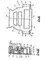
- the cover has two basic elements, namely a housing 2 (see FIG. 1) and a housing cover 3 (FIG. 2).
- the housing has three cable entry openings 4, 5 and 6, namely one (4) on the front side of the housing and one (5 and 6) on each side of the housing.
- the cable entry openings that are not required are closed by blind plugs 7 (see FIG. 5).
- the required cable entry opening can also be closed, which is of particular interest in the shielded version.
- the blind plug 7 drilled a hole that is adapted to the outer diameter of the cable and through which the cable is inserted.
- the blind plug On the side facing inwards towards the housing 2, the blind plug has a recess (not shown) for centering a drill when drilling the hole.
- a cable clamp 8 is provided for strain relief of the cable 9 in the area of the cable entry opening used.
- the cable clamp 8 can be mounted "on the envelope", ie it is reversible. It has a recess on at least one side, but preferably on both sides. The depth of the recess on one side is different from that on the other side. In the bottom of the recess pointed projections 36 (Fig. 1 F) are attached, which slightly deform the cable sheath when the clamp is screwed on, so that a form-fitting attachment is produced.
- the function of the reversible or cover-mountable cable clamp is to be able to adapt to different cable diameters. In practice, cables with the same number of cores have different diameters.
- the housing cover 3 is connected to the housing 2 here with screws 10; however, conventional snap locks can also be used. So much for the basic structure of a connector.
- the housing 2 is generally seen approximately in the shape of a shell, i. H. it has a substantially flat bottom 11 and side walls projecting therefrom, but the latter not in the lower region (bottom FIG. 1A) which is open for receiving the plug or socket strip.
- the base 11 is essentially rectangular, but in the upper region of the lateral cable entry openings 5 and 6 it is beveled.
- protrusions 12 and 13 are provided laterally beyond the rectangular contour of the base 11 and have bores 14 and 15 running parallel to the plane of the base 11, which pass completely through the extensions 12 and 13.
- the downward-facing end 16 or 17 is offset upwards relative to the lower edge 18 of the base 11, so that a step is formed there.
- the inside of the floor (top view of FIG. 1A) has a groove 19 running across the entire width of the floor 11, the upper side wall of which lies in one plane with the lower ends 16 and 17 of the lugs 12 and 13.
- the width of the groove 19 is adapted to the thickness of a circumferential carrier 21 (FIG. 6) of the plug or socket strip 1, i. H. the carrier 21 can be inserted into the groove 19.
- the approach 12 has a recess 22 on both sides of its lower end, so that a step is also formed there, starting from the plane of the bottom 11 in the direction of the interior of the housing and accordingly on the opposite side. As can best be seen from FIG. 3B, these recesses serve to ensure that between the carrier 21 of the plugs or sockets bar 1 and the approach 12 arms of a locking slide can engage.
- the extension 12 has a slot 24 in its upper region, which runs perpendicular to the plane of the bottom 11 and perpendicular to the main axis 24 of the housing.
- the slot 23 is open to the side (on the left in FIG. 1A) and to the side facing away from the base 11 and serves to receive and hold a leaf spring 25 (FIG. 3) which prestresses the locking slide 26 (FIG. 3) in one direction of movement.
- the two lugs 12 and 13 form side walls of the housing 2 in the area covered by them. As can be seen better from FIG. 1B, the lug 13 also has the recesses 22 in the area of its lower end.
- the housing has a web 27 projecting perpendicularly from the base 11 and extending perpendicular to the main axis 24, which ends on both sides in side walls of the housing, specifically in posts 28 and 29, which are perpendicular to the plane of the base 11 have bores 30 and 31, respectively, into which screws 10 (FIGS. 3A and 4A) can be screwed for fastening the housing cover 3.
- a web 32 runs parallel to the side walls of the housing, which has opposed to the cable entry openings 4, 5 and 6 respectively curved recesses 33, 34 and 35, which with a cable clamp 8 (Fig. 3A and 4A) interacts.
- two pointed projections 36 which clamp the cable, are provided one behind the other in the cable entry direction.
- Screw holes 37, 38, 39 and 40 are provided on both sides of the recesses 33, 34 and 35, the screw holes 38 and 39 on both sides of the recess 34 for the upper cable entry opening 4 also simultaneously having a side screw hole form for the recess 33 or 36.
- the cable entry axes i.e. H. the verticals on the cable entry openings 4, 5 and 6 are at an angle 41 to each other, which here is 60 °.
- the side wall 42 of the housing running parallel to the web 32 is higher, i. H. stands further from the floor 11 than the web 32. Its upper edge lies in a plane which is to be referred to as the "lid plane".
- the side wall 42 has recesses which form the cable entry openings 4, 5 and 6, respectively. Seen in the cable entry direction, these cable entry openings 4, 5, 6 are rectangular. From the outside towards the inside of the housing, the sides of the cable entry openings are provided with a recessed step 43 for holding the blind plug 7 (FIGS. 3A, 4A and 5).
- the upper side wall of the housing 2 is provided on both sides with ears 44, which serve as a handle for releasing a plug connection.
- Blind bores 45 are provided in these ears in order to avoid material accumulations during the injection molding process.
- depressions 48, 49 and 50 which serve as recessed grips and likewise serve to avoid material accumulations during injection molding.
- Fig. 2 shows the housing cover 3, the contour of which is congruent with that of the housing 2 in plan view. Parts of the cover 3 corresponding to the housing 2 are provided with the same reference numerals, which, however, have a line to distinguish them.
- the housing cover 3 is in principle a flat plate with relatively short side walls 42 ′ protruding from this plate, which are centered in the groove formed in the region of the side walls 42 of the housing 2.
- This groove of the housing 2 is formed between the elevations for the cable clamps and the elevations which have the cable entry openings 4, 5 and 6, respectively.
- the housing cover Aligned with the blind bores 30 and 31 of the housing 2, the housing cover has corresponding through bores 30 'and 31', respectively, which are arranged sunk, i. H. the housing cover 3 has depressions 51 and 52, respectively, seen from the outside thereof, the inward-facing surface 28 ', 29' resting on the posts 28 and 29 of the housing 2.
- the housing cover 3 corresponding to the groove 19 of the housing 2, also has a groove 19 'in which the plug or socket strip 1 is held.
- Fig. 3 shows a variant of a connector according to the invention with slide or quick lock.
- the basic elements have already been explained at the beginning, so that only the special features of the locking mechanism will be discussed here.
- the locking slide 26 is essentially rectangular in plan view (see FIG. 8) and has a central recess 52, the opening width of which corresponds to the width of the carrier 21 of the plug or socket strip 1.
- the locking slide 26 has inwardly projecting tongues 53 which engage in the recesses 22 on the lugs 12 and 13, their length corresponding to the depth of the recesses 22.
- the tongues 53 are thus held between the shoulders 12 and 13 of the housing 2 and the upward-facing side of the carrier 21, with which the entire locking carrier is held on the connector.
- the length of the recess 52 is greater than the length of the plug or socket strip 1, so that the locking slide can be moved in its longitudinal direction.
- an angled leaf spring 25 is inserted, the free end of which is supported on an upstanding end wall 54 of the locking slide 26. So that the locking slide is biased into a rest position, in which the connector is locked.
- the locking slide 26 On its underside, the locking slide 26 has two pairs of opposing locking lugs 55, which are arranged approximately opposite the central axes of the bores 14 and 15 in the longitudinal direction of the locking slide 26. Counterparts according to FIG. 7 are screwed onto the mating connector or mating socket strip, the locking hooks of which engage behind the locking lugs 55 and thus produce the locking.
- the locking slide 26 Opposite the end wall 50, the locking slide 26 has an end wall 57, which serves as a stop for fixing the rest position of the locking slide 26.
- the bores 14 and 15 of the lugs 12 and 13 of the housing are unused, while the recesses 22 ultimately serve to hold the locking device together with the slot 23 on the lug 12.
- the entire connector is ultimately held together only by the housing cover screws 10, since the plug or socket strip 1 is held by the grooves 19 and 19 'of the housing 2 and the housing cover 3 and the locking slide with its tongues 53 in the through the recesses 22nd and the top of the carrier 21 formed groove is held.
- FIG. 4 shows, analogously to FIG. 3, a plug connector according to the invention with a screw lock.
- Screws 58 are inserted into the two bores 14 and 15 of the lugs 12 and 13, the shank of which extends through the entire length of the bores 14 and 15 and also through bores 59 in the carrier 21 of the plug or socket strip 1 (FIG. 6).
- a threaded end 60 thus protrudes downward from the carrier 21 and can be screwed into a thread (on the mating connector or mating connector strip).
- screws can be inserted into the bores 59 of the carrier 21 of the mating connector, which screws have an internal thread on their head, into which the threaded ends 60 of the screws 58 are screwed.
- the mating connector or the mating connector strip is then attached to the housing at the same time as the screws provided with the internal thread.
- both housings can have two screws 58, the thread ends 60 of which are assigned to one another from both sides in a threaded sleeve, preferably a 6 Edge threaded sleeve (not shown) can be screwed in.
- This threaded sleeve is expediently the first screwed onto the screws on one side, then the plugs are plugged together and then "locked” by screwing the opposite screws in pairs. The threaded sleeve is only so long that the plug and socket strips can still be completely pushed into one another.
- the length of the screws 58 and in particular of the threaded ends 60 protruding from the shoulders 12 or 13 is selected such that when the screwed-in state is fully screwed in, the threaded ends 60 are less than half the length of the threaded sleeves. In other words, when the screwed state is tight, the opposite end faces of the thread ends 60 should not touch.
- the screws 58 expediently have, as is generally customary, knurled heads with a screwdriver slot. The screws 58 are secured in the housing against falling out.
- the blind plugs 7 have the shape of a rectangular plate with lateral recesses 66, so that each side protrusions 67 remain, which engage in the recesses or steps 43 of the housing 2, whereby the blind plug is secured against falling out in the cable entry direction.
- the blind plugs are secured against falling into the interior of the housing by the side wall 42. Finally, they are also held by the housing cover 3, so that they are firmly fixed in all directions.
- the blind plug shown in FIG. 5 also has a rectangular recess 68 on its underside facing the interior of the housing 2.
- the end faces of the projections 59 are provided with a chamfer 69 on both sides for easier insertion.
- FIG. 7 shows still different views of the quick-locking counterpart, which has already been mentioned in connection with FIG. 3.
- this counterpart has a U-shaped profile with a rectangular support 62, on the sides of which vertically projecting locking hooks 56 are attached. These hooks have a central web 63 on which the actual hook 56 is attached. This hook has the shape of a triangle with the tip pointing upwards.
- the locking lugs 55 (FIGS. 3B and 8) then snap behind the downward-pointing edge of the hook 56.
- the carrier 62 has a central bore 64 with which the locking hook on the carrier 21 of the plug or socket strip can be screwed through the bore 59 1 there.
- the locking hook has along one side a downwardly projecting projection 65, which serves as a stop against the end face of the carrier 21.
- the blind plugs 7 can be made of shielding or non-shielding material.
- the shielding material used in the invention consists of a thermoplastic, such as a polycarbonate, which is mixed with particles of electrically conductive material with more than 20%.
- a thermoplastic such as a polycarbonate
- particles of electrically conductive material with more than 20%.
- metal scales and especially aluminum scales are used because they do not separate during the spraying process.
- a material with 40% aluminum scales has a specific resistance of 10 ohms and has an attenuation of 99.9% in the frequency range from 0.5 to 1 GHz. from 35 to 40 dB.
- This material can be processed in conventional molds suitable for plastics, for example injection molds, and in addition to the good electrical properties also has good mechanical properties which correspond to those of the plastics used for the present application.
- This material can also be processed very well like normal plastic and does not separate during the injection or casting process.
Landscapes
- Details Of Connecting Devices For Male And Female Coupling (AREA)
- Connector Housings Or Holding Contact Members (AREA)
- External Artificial Organs (AREA)
- Mechanical Coupling Of Light Guides (AREA)
- Liquid Developers In Electrophotography (AREA)
- Liquid Crystal Substances (AREA)
- Amplifiers (AREA)
Priority Applications (1)
| Application Number | Priority Date | Filing Date | Title |
|---|---|---|---|
| AT85108447T ATE53712T1 (de) | 1984-07-13 | 1985-07-08 | Steckverbindung. |
Applications Claiming Priority (2)
| Application Number | Priority Date | Filing Date | Title |
|---|---|---|---|
| DE19843425917 DE3425917A1 (de) | 1984-07-13 | 1984-07-13 | Subminiatur-steckverbindung |
| DE3425917 | 1984-07-13 |
Publications (3)
| Publication Number | Publication Date |
|---|---|
| EP0168014A2 true EP0168014A2 (fr) | 1986-01-15 |
| EP0168014A3 EP0168014A3 (en) | 1987-06-16 |
| EP0168014B1 EP0168014B1 (fr) | 1990-06-13 |
Family
ID=6240605
Family Applications (1)
| Application Number | Title | Priority Date | Filing Date |
|---|---|---|---|
| EP85108447A Expired - Lifetime EP0168014B1 (fr) | 1984-07-13 | 1985-07-08 | Système de couplage |
Country Status (3)
| Country | Link |
|---|---|
| EP (1) | EP0168014B1 (fr) |
| AT (1) | ATE53712T1 (fr) |
| DE (2) | DE3425917A1 (fr) |
Cited By (2)
| Publication number | Priority date | Publication date | Assignee | Title |
|---|---|---|---|---|
| US5831815A (en) * | 1997-03-31 | 1998-11-03 | The Whitaker Corporation | Programmable backshell for an electrical connector |
| WO2012069819A1 (fr) * | 2010-11-22 | 2012-05-31 | C.P. Electronics | Connecteur de puissance |
Families Citing this family (2)
| Publication number | Priority date | Publication date | Assignee | Title |
|---|---|---|---|---|
| DE29801984U1 (de) | 1998-02-06 | 1998-03-26 | Schmitt, Fred R., 74388 Talheim | Steckverbinder-Gehäuse im 19 Zoll-Gerätesystem |
| RU2161354C1 (ru) * | 2000-03-06 | 2000-12-27 | Открытое акционерное общество "Ракетно-космическая корпорация "Энергия" имени С.П. Королева" | Электрический соединитель |
Family Cites Families (14)
| Publication number | Priority date | Publication date | Assignee | Title |
|---|---|---|---|---|
| FR1376777A (fr) * | 1962-09-27 | 1964-10-31 | Malco Mfg Co | Procédé et appareil d'enfichage pour connecteurs à bornes |
| US3316523A (en) * | 1964-11-20 | 1967-04-25 | George J Trangmar | Electrical cord accessory |
| DE2013884C3 (de) * | 1970-03-23 | 1975-01-23 | Siemens Ag, 1000 Berlin Und 8000 Muenchen | Steckvorrichtung |
| DE7231467U (de) * | 1972-08-25 | 1977-09-08 | Siemens Ag, 1000 Berlin Und 8000 Muenchen | Anordnung für verriegelbare Steckverbindungen |
| DE2336611A1 (de) * | 1973-07-18 | 1975-01-30 | Siemens Ag | Frontsteckeranordnung fuer leiterplatten |
| IT1066911B (it) * | 1976-07-05 | 1985-03-12 | Itw Fastex Italia Spa | Connettore per apparecchiature elettriche |
| US4113179A (en) * | 1976-10-29 | 1978-09-12 | Trw Inc. | Connector constructions and attaching means therefor |
| DE7811705U1 (de) * | 1978-04-19 | 1978-08-31 | Wilhelm Harting Werk Fuer Elektrotechnik Und Mechanik Gmbh, 4992 Espelkamp | Griffteil mit zugentlastungseinrichtung fuer elektrische steckverbinder |
| DE2824009A1 (de) * | 1978-06-01 | 1979-12-06 | Harting Elektronik Gmbh | Einrichtung zur zugentlastung fuer griffteile elektrischer steckverbinder |
| US4332432A (en) * | 1978-12-06 | 1982-06-01 | Molex Incorporated | Low insertion force connector assembly |
| FR2455374A1 (fr) * | 1979-04-25 | 1980-11-21 | Cit Alcatel | Dispositif de verrouillage de connecteur |
| DE3036015A1 (de) * | 1980-09-24 | 1982-04-08 | Siemens AG, 1000 Berlin und 8000 München | Bolzensicherung fuer einen trapezsteckverbinder |
| DE3041938C2 (de) * | 1980-11-06 | 1987-05-07 | Allied Corp., Morris Township, N.J. | Verriegelbare Steckverbindung mit einem einen Steckverbinder umgebenden Steckergehäuse |
| DE8137081U1 (de) * | 1981-12-19 | 1983-01-20 | Robert Bosch Gmbh, 7000 Stuttgart | Elektrische Steckvorrichtung |
-
1984
- 1984-07-13 DE DE19843425917 patent/DE3425917A1/de not_active Withdrawn
-
1985
- 1985-07-08 EP EP85108447A patent/EP0168014B1/fr not_active Expired - Lifetime
- 1985-07-08 DE DE8585108447T patent/DE3578277D1/de not_active Expired - Fee Related
- 1985-07-08 AT AT85108447T patent/ATE53712T1/de not_active IP Right Cessation
Cited By (2)
| Publication number | Priority date | Publication date | Assignee | Title |
|---|---|---|---|---|
| US5831815A (en) * | 1997-03-31 | 1998-11-03 | The Whitaker Corporation | Programmable backshell for an electrical connector |
| WO2012069819A1 (fr) * | 2010-11-22 | 2012-05-31 | C.P. Electronics | Connecteur de puissance |
Also Published As
| Publication number | Publication date |
|---|---|
| DE3425917A1 (de) | 1986-01-16 |
| EP0168014A3 (en) | 1987-06-16 |
| EP0168014B1 (fr) | 1990-06-13 |
| DE3578277D1 (de) | 1990-07-19 |
| ATE53712T1 (de) | 1990-06-15 |
Similar Documents
| Publication | Publication Date | Title |
|---|---|---|
| DE3041938C2 (de) | Verriegelbare Steckverbindung mit einem einen Steckverbinder umgebenden Steckergehäuse | |
| DE2709604C2 (fr) | ||
| DE102004038123B4 (de) | Elektrischer Stecker und elektrische Steckeraufnahme | |
| DE68905501T2 (de) | Verteiler mit quetschbacken fuer verkabelungszubehoer, insbesondere fuer endstuecke. | |
| DE19543009C2 (de) | Verriegelungsmechanismus für ein elektrisches Steckverbinderpaar | |
| DE8700210U1 (de) | Verbindungsanordnung mit Anhebe-Zahnstangen | |
| DE7725705U1 (de) | Elektrischer Verbinder | |
| DE102006016882A1 (de) | Steckverbinder | |
| DE8800759U1 (de) | Elektrischer Verbinder mit beweglichem Führungselement | |
| DE2639811A1 (de) | Elektrische verbindereinheit zum anschliessen eines mehrleiter-flachkabels | |
| DE3004390A1 (de) | Gehaeuse fuer elektrische leitungsverbindungen | |
| DE2811775A1 (de) | Pruefvorrichtung | |
| DE2212807A1 (de) | Elektrische Anschlussklemme | |
| DE69019029T2 (de) | Zugentlastungseinrichtung. | |
| DE69515968T2 (de) | Verbinderanordnung mit zusammenwirkenden Kontaktteilen und ein Verfahren zum Verbinden derselben | |
| DE3313144A1 (de) | Steckeranordnung | |
| EP0168014B1 (fr) | Système de couplage | |
| DE3035252C2 (de) | Buchsenteil einer elektrischen Steckverbinderanordnung | |
| DE9304393U1 (de) | Steckverbinder mit Leitungsaustrittskanal | |
| DE102024100302A1 (de) | Abzweigverbinder | |
| DE4411731B4 (de) | Aufputz-Steckdose | |
| DE8521953U1 (de) | Elektrischer Stecker | |
| DE19953646A1 (de) | Steckverbindungssystem für folienisolierte Leiter | |
| DE1440752A1 (de) | Kombinations-Klemmenhalterung und damit ausgestattete Klemmenleiste | |
| DE8420661U1 (de) | Elektrischer Hilfsanschluss |
Legal Events
| Date | Code | Title | Description |
|---|---|---|---|
| PUAI | Public reference made under article 153(3) epc to a published international application that has entered the european phase |
Free format text: ORIGINAL CODE: 0009012 |
|
| AK | Designated contracting states |
Designated state(s): AT BE CH DE FR GB IT LI LU NL SE |
|
| PUAL | Search report despatched |
Free format text: ORIGINAL CODE: 0009013 |
|
| AK | Designated contracting states |
Kind code of ref document: A3 Designated state(s): AT BE CH DE FR GB IT LI LU NL SE |
|
| 17P | Request for examination filed |
Effective date: 19870806 |
|
| ITF | It: translation for a ep patent filed | ||
| 17Q | First examination report despatched |
Effective date: 19881208 |
|
| GRAA | (expected) grant |
Free format text: ORIGINAL CODE: 0009210 |
|
| AK | Designated contracting states |
Kind code of ref document: B1 Designated state(s): AT BE CH DE FR GB IT LI LU NL SE |
|
| PG25 | Lapsed in a contracting state [announced via postgrant information from national office to epo] |
Ref country code: SE Effective date: 19900613 Ref country code: NL Effective date: 19900613 Ref country code: GB Effective date: 19900613 Ref country code: FR Effective date: 19900613 Ref country code: BE Effective date: 19900613 |
|
| REF | Corresponds to: |
Ref document number: 53712 Country of ref document: AT Date of ref document: 19900615 Kind code of ref document: T |
|
| PG25 | Lapsed in a contracting state [announced via postgrant information from national office to epo] |
Ref country code: AT Effective date: 19900708 |
|
| REF | Corresponds to: |
Ref document number: 3578277 Country of ref document: DE Date of ref document: 19900719 |
|
| PGFP | Annual fee paid to national office [announced via postgrant information from national office to epo] |
Ref country code: DE Payment date: 19900727 Year of fee payment: 6 |
|
| PG25 | Lapsed in a contracting state [announced via postgrant information from national office to epo] |
Ref country code: LU Free format text: LAPSE BECAUSE OF NON-PAYMENT OF DUE FEES Effective date: 19900731 Ref country code: LI Effective date: 19900731 Ref country code: CH Effective date: 19900731 |
|
| EN | Fr: translation not filed | ||
| NLV1 | Nl: lapsed or annulled due to failure to fulfill the requirements of art. 29p and 29m of the patents act | ||
| GBV | Gb: ep patent (uk) treated as always having been void in accordance with gb section 77(7)/1977 [no translation filed] | ||
| REG | Reference to a national code |
Ref country code: CH Ref legal event code: PL |
|
| PLBE | No opposition filed within time limit |
Free format text: ORIGINAL CODE: 0009261 |
|
| STAA | Information on the status of an ep patent application or granted ep patent |
Free format text: STATUS: NO OPPOSITION FILED WITHIN TIME LIMIT |
|
| 26N | No opposition filed | ||
| PG25 | Lapsed in a contracting state [announced via postgrant information from national office to epo] |
Ref country code: DE Effective date: 19920401 |