EP0168021A1 - Chariot pour un dispositif de sécurité pour la montée d'une échelle - Google Patents
Chariot pour un dispositif de sécurité pour la montée d'une échelle Download PDFInfo
- Publication number
- EP0168021A1 EP0168021A1 EP85108468A EP85108468A EP0168021A1 EP 0168021 A1 EP0168021 A1 EP 0168021A1 EP 85108468 A EP85108468 A EP 85108468A EP 85108468 A EP85108468 A EP 85108468A EP 0168021 A1 EP0168021 A1 EP 0168021A1
- Authority
- EP
- European Patent Office
- Prior art keywords
- profile
- guide
- carriage
- parts
- pawl
- Prior art date
- Legal status (The legal status is an assumption and is not a legal conclusion. Google has not performed a legal analysis and makes no representation as to the accuracy of the status listed.)
- Granted
Links
- 230000009194 climbing Effects 0.000 title claims abstract description 12
- 238000003780 insertion Methods 0.000 claims description 10
- 230000037431 insertion Effects 0.000 claims description 10
- 230000006835 compression Effects 0.000 description 6
- 238000007906 compression Methods 0.000 description 6
- 229910000831 Steel Inorganic materials 0.000 description 1
- XAGFODPZIPBFFR-UHFFFAOYSA-N aluminium Chemical compound [Al] XAGFODPZIPBFFR-UHFFFAOYSA-N 0.000 description 1
- 229910052782 aluminium Inorganic materials 0.000 description 1
- 239000004020 conductor Substances 0.000 description 1
- 238000010276 construction Methods 0.000 description 1
- 210000003811 finger Anatomy 0.000 description 1
- 239000010959 steel Substances 0.000 description 1
- 210000003813 thumb Anatomy 0.000 description 1
Images
Classifications
-
- E—FIXED CONSTRUCTIONS
- E06—DOORS, WINDOWS, SHUTTERS, OR ROLLER BLINDS IN GENERAL; LADDERS
- E06C—LADDERS
- E06C7/00—Component parts, supporting parts, or accessories
- E06C7/18—Devices for preventing persons from falling
- E06C7/186—Rail or rope for guiding a safety attachment, e.g. a fall arrest system
- E06C7/187—Guiding rail
Definitions
- the invention relates to a slide for a fall arrest device for climbing a ladder, the slide sliding in a guide with a C-profile that is open to the front and that form guide flanges that delimit the opening of the C-profile lips of the C-profile, the slide having guide devices that encompass the guide flanges and parts of the guide devices are designed to be rotatable in order to release the engagement with the guide flanges and to take the slide out of the guide and to be able to insert it into the slide, the slide also has means for fastening a seat belt and a pawl which is spring-loaded in one Locked position is held, and the pawl cooperates with stop surfaces arranged at intervals inside the C-profile of the guide.
- Such a carriage is known from DE-OS 27 36 037.
- the parts of the guide devices encompassing the one guide flange are designed to be pivotable about an axis running parallel to the guide, so that they can be moved in the direction of the parts of the guide devices encompassing the other guide flange, as a result of which the slide can then be removed from the guide.
- To lock the guide devices in the safety position either a threaded bolt is tightened by means of a socket wrench or an additional locking pin must be provided, as a result of which the construction of the slide is more complex.
- the invention has for its object to improve a slide of the type mentioned in such a way that it can be locked in its secured position without the aid of tools and can be brought from the secured position into the inserted position in a simple manner.
- the rotatable parts of the guide devices preferably snap into the securing position and the inserted position.
- the carriage is preferably also guided by rollers.
- the slide according to the invention can be used at any point along a guide, which is formed by a C profile which is open at the front, and the guide devices can then be brought into their securing position in a few steps, in which the slide slides securely in the guide. Failure of the fall arrest device due to careless handling of the slide is largely excluded.
- the guide can also be the central spar of a vertical ladder, as described in DE-PS 19 61 757.
- the ladder rungs penetrate the central strut at regular intervals and the section of the step surfaces of the ladder rungs located inside the C-profile also serves as a stop surface for the pawl of the slide.
- the guide rail 1 serves as a guide for the carriage, as is explained in DE-PS 19 61 757.
- each rail can serve as a guide with an open C-profile.
- the stop surfaces can then protrude inwards, for example, from the rear of the C-profile, as shown in D E-OS 31 29 991.
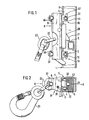
- the guide rail 1 which forms the guide has a C profile which is open towards the front and has profile side walls 4 which are connected by a profile rear and have profile lips 6 which point towards one another at the front and which delimit an opening 7 between them.
- the profile lips 6 serve as guide flanges.
- the carriage 8 consists of a generally rectangular body 9 which is guided along the ladder stile 1 by guide devices 10.
- a pawl 18 is rotatably mounted on a pin 19 in a slot-shaped opening 11 in the slide 8.
- the pawl nose 20 of the pawl 18 protrudes rearward from the body 9 and into the interior of the C-profile of the ladder stile 1 to the extent that the pawl nose 20 can lie against the stop faces 5.
- the pawl 18 is mounted at its upper end by means of the pin 19 and the back 21 of the pawl nose 20 is chamfered downwards from the pin bearing.
- On its front side the pawl is provided with an eyelet 22, on which e.g. a safety belt can be fastened by means of a snap hook 23, which a person climbing the ladder wears.
- the pawl 18 is under the action of a compression spring 25 which presses against the pawl 18 above the journal bearing and a tension spring 27 which engages the pawl 18 below the journal bearing.
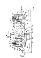
- the compression spring 25 and the tension spring 27 both try to turn the pawl 18 in FIG. 4 counterclockwise and into the locking position shown in solid lines to bring, in which the pawl nose 20 can be supported on a stop surface 5. If the carriage is pulled up by a person climbing the ladder, the back 21 of the pawl nose 20 comes to rest against the stop faces 5 from below and is pressed forward due to its bevel, so that the pawl 18 is pivoted clockwise and the stop faces 5 can run over.
- the eyelet 22 is attached obliquely to the front below the journal bearing, so that the pawl 18 is also pivoted clockwise when an upward or forward pull is exerted on the eyelet 22, for example by the person climbing the ladder.
- a downward pull is exerted on the eyelet 22 which, in addition to the action of the compression spring 25 and the tension spring 27, attempts to turn the pawl 18 into the locking position.
- the pawl 18 When descending, the pawl 18 must be pivoted clockwise by hand against the spring force of the springs 25 and 27 to drive over a stop surface 5. This is done in that a pull directed away from the stile 1 is exerted on the eyelet 22.
- This position of the pawl 22 is shown in Fig. 4 by a broken line.
- the pawl 22 is consequently pressed into its locked position by the downward train which occurs in the event of a crash.
- a recess 29 is provided, into which a stop pin 30 attached to the body 9 projects. The recess 29 and the stop pin 30 limit the movement of the pawl 18th
- the carriage 8 is guided by guide devices which engage on the outside and inside on the profile lips 6 serving as guide flanges.
- the guide means have outer rollers 31 which are on the body 9 are stored and run on the outside of the profile lips 6, as well as inner rollers 32 which roll on the inside of the profile lips 6.
- Two inner rollers 32 each are mounted on two shafts 33, which in turn are rotatably mounted in the body 9 above and below the pawl 18.
- the axis of the shaft 33 runs perpendicular to the opening 7, and the axis of the inner rollers 32 runs transverse to that of the shaft 33.
- the shaft 33 is secured in the body 9 against falling out.
- the shaft 33 has a groove 34, approximately in the middle of its length, which tangentially engages with a securing threaded pin 35 which is screwed into the block 9.
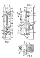
- the inner rollers can be brought into a securing position and an insertion position.
- the axis of the inner rollers 32 is parallel to that of the outer rollers 31 and thus transversely to the opening 7, so that the carriage 8 is guided safely along the ladder rail 1 by the outer and inner rollers 31, 32.
- the shaft 33 90 By rotating the shaft 33 90 0, the carriage is brought into the insertion position.
- the axis of the inner rollers 32 then points in the longitudinal direction of the opening 7 and thus in the longitudinal direction of the ladder spar 1.
- the inner rollers 32 are therefore no longer in contact with the inside of the profile lips 6 and the carriage 8 can be lifted off the ladder spar 1. So that the inner rollers 32 can pass through the opening 7 when the carriage 8 is lifted off the ladder bar 1, the diameter of the inner rollers 32 is smaller than the width of the opening 7. So that the shaft end does not lock in the opening 7 when the shaft 33 is rotated, it is expediently cylindrical, and the cylinder diameter is somewhat smaller than the width of the opening 7.
- the distance between the inner rollers 32 corresponds approximately to the width of the opening 7, and the width of the inner roller 32 corresponds approximately to the height of the P ro- fillippen 6, so that the inner rollers can run in the S iche- approximate position without too much play within the C-profile 32nd
- the two shafts 33 engage in the securing position or the inserted position.
- the front end of the shaft 33 projects beyond the body 9 and has a transverse opening 36 in which a wing handle 37 is arranged.
- the wing handle 37 is fixed by a screw which is screwed coaxially into the front end of the shaft 33 and extends over the transverse opening 36 and is pressed against the body 9 by a compression spring 39 seated on the screw 38.
- the wing handle 37 is expediently arranged parallel to the axis of the inner rollers 32, so that the position of the wing handle 37 corresponds to the position of the inner rollers 32.
- the locking grooves 40 consist of a horizontal and a vertical groove.
- the storage and securing of the shaft 33 and the locking mechanism are identical in the lower two of the inner rollers 32 and in the upper two inner rollers 32.
- the head of the shafts 33 such that even if only one of the two inner pairs of rollers is rotated into the securing position, the carriage 8 already prevents the person climbing the ladder from falling, ie even then the pawl 18 comes to rest against the stop surfaces 5 and thus the stop surfaces 5 without manual Pivoting the pawl 18 can not be run over.
- the head of the upper shaft 33 is provided at its front end with a securing lug 42 which projects upwards in its securing position and is somewhat rounded at the front at 44.
- the head of the lower shaft 33 is provided at its front end with a securing lug 42 which projects downward in its securing position and is also somewhat rounded at the front at 44.
- the shafts 33 are each rotated so that the locking lugs 42 point to the same side, in the illustrated embodiment to the right.
- the possibility of rotation of the wing handles 37 is limited so that they can only be rotated in one direction from the secured position to the inserted position, in the illustrated embodiment by rotating the upper wing handle 37 90 * clockwise and the lower wing handle 37 by 90 ° counterclockwise - each seen in Fig. 3. This is necessary because the ribs 42 at the head end of the two shafts 33 must point to the same side in order to insert and remove the slide 8.
- D ate disposed in the interior of the C-profile parts 16 of the guide means 10 may have a transverse dimension in the insertion position, which is smaller than the width of the opening 7 of the C-profile is to be understood so that the transverse dimension in consideration of for the insertion and removal of the carriage 8 required rotation about the vertical is determined.
- the inner rollers 32 are brought into their insertion position.
- the wing handle 37 is gripped at both ends with the thumb and index finger and lifted off the body 9 against the force of the compression spring 39, so that the shaft 33 can be rotated.
- the two shafts 33 are rotated so that the axes of the inner rollers 32 in the longitudinal direction, i.e. Show direction of movement of the carriage 8.
- the locking lugs 42 point to the right. In this position, the carriage 8 can be placed on the ladder bar 1, the pawl 18 and the head of the shafts 33 with the inner rollers 32 and the locking lugs 42 projecting into the interior of the C-profile.
- the carriage 8 is then pressed to the right on the right profile lip 6, so that the locking lugs 42 come to lie behind this profile lip 6 of the ladder rail 1.
- the body 9 of the carriage 8 is then fully pressed against the ladder stile 1, while with the other hand one of the wing handles 37 is lifted off the body 9 and rotated through 90 °, so that the axes of the inner rollers 32 now cross extend to the handlebar 1.
- the wing handle 37 engages again in this position.
- the other shaft 33 is rotated by 90 °, again engaging in the transverse groove of the locking groove 40.
- the carriage 8 is thus securely connected to the ladder rail 1 and can slide along it and fulfill its safety function.
- the inner pairs of rollers 32 are first placed parallel to the longitudinal direction of the ladder stile 1 by turning the wing handles 37. Then, the carriage 8 by one to the longitudinal direction of the L pus frame 1 parallel axis slightly in a counterclockwise direction - seen in Fig. 6 - pivoted so that the locking lugs 42 can pass through the opening 7 and the carriage 8 can be removed from the conductor rail 1.
- the carriage 8 must of course always be inserted into the opening 7 of the ladder stile 1 in such a way that the back of the pawl nose 20 points upwards. Additional safety devices are expediently provided, which prevent incorrect insertion of the slide 8.
- a locking pin 47 protrudes laterally from the body 9 of the carriage 8, which interacts at the upper and lower ends of the ladder rail 1 with known guide means and firstly prevents the carriage 8 from accidentally falling out at the lower and upper ends of the ladder rail 1 and secondly incorrect insertion of the carriage 8 at the lower and upper ends of the ladder rail 1 is excluded.
- the carriage 8 can be inserted or removed in the usual manner without the need to pivot the shafts 33 into the inserted position.
- the carriage 8 is not only provided with appropriate markings, but expediently has an additional one Lock lever 48 on.
- the locking lever 48 is mounted at the lower end of the slide 8 in a downwardly open slot pointing towards the opening 7 and, when the slide 8 is in the correct position, falls somewhat out of this slot.
- the locking lever 48 projects into the opening 7 about as far as the lower shaft 33 into it.
- the inner rollers 32 are not always necessary. They can be replaced by simple sliding surfaces on the head of the shaft 33. Likewise, the outer rollers 31 can be omitted, so that the body 9 slides directly on the outside of the profile lips 6.
- the guide can be the ladder spar 1 of a single-spar ladder or an additional central spar of a conventional ladder with two side spars.
- the climbing protection device described above can in principle be used in connection with any type of climbing devices.
- the carriage 8 is generally made of aluminum for reasons of weight, the highly stressed parts, e.g. the pawl 18, the rollers, etc. can also be made of high-strength steel.
Landscapes
- Engineering & Computer Science (AREA)
- Mechanical Engineering (AREA)
- Ladders (AREA)
- Organic Low-Molecular-Weight Compounds And Preparation Thereof (AREA)
- Saccharide Compounds (AREA)
- Breakers (AREA)
- Lead Frames For Integrated Circuits (AREA)
- Electrical Discharge Machining, Electrochemical Machining, And Combined Machining (AREA)
- Confectionery (AREA)
- Movable Scaffolding (AREA)
- Control And Safety Of Cranes (AREA)
- Types And Forms Of Lifts (AREA)
Priority Applications (1)
| Application Number | Priority Date | Filing Date | Title |
|---|---|---|---|
| AT85108468T ATE31342T1 (de) | 1984-07-13 | 1985-07-09 | Schlitten fuer eine steigschutzvorrichtung zum besteigen einer leiter. |
Applications Claiming Priority (2)
| Application Number | Priority Date | Filing Date | Title |
|---|---|---|---|
| DE19843425947 DE3425947A1 (de) | 1984-07-13 | 1984-07-13 | Schlitten fuer eine steigschutzvorrichtung zum besteigen einer leiter |
| DE3425947 | 1984-07-13 |
Publications (2)
| Publication Number | Publication Date |
|---|---|
| EP0168021A1 true EP0168021A1 (fr) | 1986-01-15 |
| EP0168021B1 EP0168021B1 (fr) | 1987-12-09 |
Family
ID=6240620
Family Applications (1)
| Application Number | Title | Priority Date | Filing Date |
|---|---|---|---|
| EP85108468A Expired EP0168021B1 (fr) | 1984-07-13 | 1985-07-09 | Chariot pour un dispositif de sécurité pour la montée d'une échelle |
Country Status (8)
| Country | Link |
|---|---|
| EP (1) | EP0168021B1 (fr) |
| AT (1) | ATE31342T1 (fr) |
| AU (1) | AU568942B2 (fr) |
| DE (2) | DE3425947A1 (fr) |
| ES (1) | ES295997Y (fr) |
| FI (1) | FI75396C (fr) |
| NO (1) | NO163338C (fr) |
| ZA (1) | ZA855269B (fr) |
Cited By (22)
| Publication number | Priority date | Publication date | Assignee | Title |
|---|---|---|---|---|
| EP0330642A1 (fr) * | 1988-02-24 | 1989-08-30 | Jomy S.A. | Nacelle mobile sur échelle |
| EP0418405A1 (fr) * | 1989-09-16 | 1991-03-27 | Fahrleitungsbau GmbH | Dispositif de blocage pour une installation anti-chute |
| DE29501716U1 (de) * | 1995-02-03 | 1995-03-16 | Söll GmbH, 95028 Hof | Fangeinrichtung für ein Steigschutzsystem |
| FR2745030A1 (fr) * | 1996-02-20 | 1997-08-22 | Komet | Nacelle de travail destinee a etre utilisee sur une echelle |
| DE29712753U1 (de) * | 1997-07-18 | 1997-09-11 | Söll GmbH, 95028 Hof | Versenkbare Verlängerung der Führungsschiene einer Steigschutzvorrichtung |
| EP0812606A3 (fr) * | 1996-06-12 | 1999-03-10 | Söll Gmbh | Dispositif pour grimper |
| WO2000060209A1 (fr) | 1999-04-01 | 2000-10-12 | Söll Gmbh | Appareil de capture |
| WO2001040611A2 (fr) | 1999-11-29 | 2001-06-07 | Christian Dalloz Holding Deutschland Gmbh & Co. Kg | Dispositif de blocage pour systeme anti-chute |
| EP1111151A3 (fr) * | 1999-12-24 | 2002-01-09 | Total Fabrications Limited | Eléments structurels et parties associées |
| WO2005026491A1 (fr) | 2003-09-12 | 2005-03-24 | Christian Dalloz Holding Deutschland Gmbh & Co. Kg | Appareil d'absorption faisant partie d'un absorbeur d'energie pour cables et elements d'ascension analogues |
| WO2008046446A1 (fr) * | 2006-10-16 | 2008-04-24 | Christian Dalloz Holding Deutschland Gmbh & Co. Kg | Dispositif de blocage pour un système anti-chute |
| EP1253280A3 (fr) * | 2001-04-20 | 2008-12-03 | New Technelec S.A. | Equipement pour ancrage de sécurité |
| CN101975020A (zh) * | 2010-10-29 | 2011-02-16 | 新疆电力公司乌鲁木齐电业局 | 改进型双分裂软梯悬挂头 |
| US8550225B2 (en) | 2009-10-23 | 2013-10-08 | D B Industries, Llc | Energy absorber |
| CN104314459A (zh) * | 2014-10-31 | 2015-01-28 | 国家电网公司 | 自闭锁软梯 |
| EP2870982A2 (fr) | 2013-11-11 | 2015-05-13 | Honeywell International Inc. | Système de contrôle de corps d'arrêt de chutes de type guidé |
| CN104821518A (zh) * | 2015-06-03 | 2015-08-05 | 国网冀北电力有限公司唐山供电公司 | 带自锁装置的软梯头 |
| US9132297B2 (en) | 2012-07-18 | 2015-09-15 | D B Industries, Llc | Rope grab |
| US9168402B2 (en) | 2012-07-18 | 2015-10-27 | D B Industries, Llc | Rope grab |
| WO2015183564A1 (fr) | 2014-05-29 | 2015-12-03 | Honeywell International Inc. | Commande de la force d'un dispositif antichute du type guidé |
| KR102553671B1 (ko) * | 2023-03-24 | 2023-07-10 | 이윤환 | 사다리용 수직 추락 방지 장치 |
| KR102585960B1 (ko) * | 2023-06-29 | 2023-10-06 | 양현수 | 작업자 추락방지 기능을 구비한 고소작업차량 |
Families Citing this family (6)
| Publication number | Priority date | Publication date | Assignee | Title |
|---|---|---|---|---|
| USD722487S1 (en) | 2013-05-10 | 2015-02-17 | D B Industries, Llc | Housing assembly of a rope grab |
| USD739212S1 (en) | 2013-05-10 | 2015-09-22 | D B Industries, Llc | Housing of a rope grab |
| USD710678S1 (en) | 2013-05-10 | 2014-08-12 | D B Industries, Llc | Energy absorbing locking arm of a rope grab |
| USD764258S1 (en) | 2013-05-10 | 2016-08-23 | D B Industries, Llc | Housing of a rope grab |
| USD710679S1 (en) | 2013-05-10 | 2014-08-12 | D B Industries, Llc | Locking arm of a rope grab |
| USD746125S1 (en) | 2013-05-10 | 2015-12-29 | D B Industries, Llc | Fixed side plate of a rope grab |
Citations (4)
| Publication number | Priority date | Publication date | Assignee | Title |
|---|---|---|---|---|
| DE1784726B1 (de) * | 1968-09-11 | 1971-09-23 | Fahrleitungsbau Gmbh | Absturzsicherung, insbesondere für Leitern |
| DE2736037A1 (de) * | 1977-08-10 | 1979-02-22 | Soell Ind Schmiede | Steigschutzvorrichtung zum besteigen einer leiter |
| WO1982000006A1 (fr) * | 1980-06-24 | 1982-01-07 | F Graham | Appareil de sauvetage incendie ameliore |
| FR2514069A1 (fr) * | 1981-10-05 | 1983-04-08 | Bilco Co | Allonge coulissante de securite pour echelle |
Family Cites Families (4)
| Publication number | Priority date | Publication date | Assignee | Title |
|---|---|---|---|---|
| DE2060718B2 (de) * | 1970-12-10 | 1973-08-02 | Fahrleitungsbau Gmbh, 4300 Essen | Absturzsicherung an leitern oder aehnlichen vorrichtungen |
| AU484009B2 (en) * | 1972-05-01 | 1974-11-07 | Gibson William | Safety device for ladders and the like |
| US4111280A (en) * | 1977-01-31 | 1978-09-05 | Norton Company | Supporting guide rail for ladder safety device |
| FR2385881A1 (fr) * | 1977-03-30 | 1978-10-27 | Aumont Ets | Dispositif de securite, pour echelle |
-
1984
- 1984-07-13 DE DE19843425947 patent/DE3425947A1/de not_active Ceased
-
1985
- 1985-07-08 FI FI852695A patent/FI75396C/fi not_active IP Right Cessation
- 1985-07-09 DE DE8585108468T patent/DE3561167D1/de not_active Expired
- 1985-07-09 AU AU44703/85A patent/AU568942B2/en not_active Ceased
- 1985-07-09 EP EP85108468A patent/EP0168021B1/fr not_active Expired
- 1985-07-09 AT AT85108468T patent/ATE31342T1/de not_active IP Right Cessation
- 1985-07-11 ES ES1985295997U patent/ES295997Y/es not_active Expired
- 1985-07-12 ZA ZA855269A patent/ZA855269B/xx unknown
- 1985-07-12 NO NO852808A patent/NO163338C/no unknown
Patent Citations (4)
| Publication number | Priority date | Publication date | Assignee | Title |
|---|---|---|---|---|
| DE1784726B1 (de) * | 1968-09-11 | 1971-09-23 | Fahrleitungsbau Gmbh | Absturzsicherung, insbesondere für Leitern |
| DE2736037A1 (de) * | 1977-08-10 | 1979-02-22 | Soell Ind Schmiede | Steigschutzvorrichtung zum besteigen einer leiter |
| WO1982000006A1 (fr) * | 1980-06-24 | 1982-01-07 | F Graham | Appareil de sauvetage incendie ameliore |
| FR2514069A1 (fr) * | 1981-10-05 | 1983-04-08 | Bilco Co | Allonge coulissante de securite pour echelle |
Cited By (35)
| Publication number | Priority date | Publication date | Assignee | Title |
|---|---|---|---|---|
| EP0330642A1 (fr) * | 1988-02-24 | 1989-08-30 | Jomy S.A. | Nacelle mobile sur échelle |
| EP0418405A1 (fr) * | 1989-09-16 | 1991-03-27 | Fahrleitungsbau GmbH | Dispositif de blocage pour une installation anti-chute |
| DE29501716U1 (de) * | 1995-02-03 | 1995-03-16 | Söll GmbH, 95028 Hof | Fangeinrichtung für ein Steigschutzsystem |
| WO1996023951A1 (fr) * | 1995-02-03 | 1996-08-08 | Söll Gmbh | Dispositif d'arret pour systeme de protection dans des activites grimpantes |
| FR2745030A1 (fr) * | 1996-02-20 | 1997-08-22 | Komet | Nacelle de travail destinee a etre utilisee sur une echelle |
| EP0812606A3 (fr) * | 1996-06-12 | 1999-03-10 | Söll Gmbh | Dispositif pour grimper |
| WO1999004127A1 (fr) | 1997-07-18 | 1999-01-28 | Söll Gmbh | Prolongement escamotable du rail de guidage d'un dispositif de protection de montee |
| DE29712753U1 (de) * | 1997-07-18 | 1997-09-11 | Söll GmbH, 95028 Hof | Versenkbare Verlängerung der Führungsschiene einer Steigschutzvorrichtung |
| US6260662B1 (en) | 1997-07-18 | 2001-07-17 | Soll Gmbh | Rectractable extension for the guiding rail of a climbing guard |
| WO2000060209A1 (fr) | 1999-04-01 | 2000-10-12 | Söll Gmbh | Appareil de capture |
| WO2001040611A2 (fr) | 1999-11-29 | 2001-06-07 | Christian Dalloz Holding Deutschland Gmbh & Co. Kg | Dispositif de blocage pour systeme anti-chute |
| WO2001040611A3 (fr) * | 1999-11-29 | 2001-11-22 | Christian Dalloz Holding Deuts | Dispositif de blocage pour systeme anti-chute |
| CZ301395B6 (cs) * | 1999-11-29 | 2010-02-17 | Christian Dalloz Holding Deutschland Gmbh And Co. Kg | Záchytné ústrojí pro stoupací ochranný systém |
| EP1111151A3 (fr) * | 1999-12-24 | 2002-01-09 | Total Fabrications Limited | Eléments structurels et parties associées |
| US6408587B2 (en) | 1999-12-24 | 2002-06-25 | Total Fabrications Limited | Structural members and associated parts |
| EP1253280A3 (fr) * | 2001-04-20 | 2008-12-03 | New Technelec S.A. | Equipement pour ancrage de sécurité |
| WO2005026491A1 (fr) | 2003-09-12 | 2005-03-24 | Christian Dalloz Holding Deutschland Gmbh & Co. Kg | Appareil d'absorption faisant partie d'un absorbeur d'energie pour cables et elements d'ascension analogues |
| US7708116B2 (en) | 2003-09-12 | 2010-05-04 | Christian Dalloz Holding Deutschland Gmbh & Co. K, | Fall arrester as part of a fall protection system for ladders and similar climbing routes |
| AU2004272767B2 (en) * | 2003-09-12 | 2010-07-15 | Honeywell Fall Protection Deutschland Gmbh & Co. Kg | Catch device as part of a fall protection for ladders and similar climbing devices |
| US8584797B2 (en) | 2006-10-16 | 2013-11-19 | Honeywell Fall Protection Deutschland Gmbh & Co. Kg | Fall arrester for a climbing protection system |
| WO2008046446A1 (fr) * | 2006-10-16 | 2008-04-24 | Christian Dalloz Holding Deutschland Gmbh & Co. Kg | Dispositif de blocage pour un système anti-chute |
| US8550225B2 (en) | 2009-10-23 | 2013-10-08 | D B Industries, Llc | Energy absorber |
| CN101975020B (zh) * | 2010-10-29 | 2015-06-17 | 新疆电力公司乌鲁木齐电业局 | 改进型双分裂软梯悬挂头 |
| CN101975020A (zh) * | 2010-10-29 | 2011-02-16 | 新疆电力公司乌鲁木齐电业局 | 改进型双分裂软梯悬挂头 |
| US9168402B2 (en) | 2012-07-18 | 2015-10-27 | D B Industries, Llc | Rope grab |
| US9132297B2 (en) | 2012-07-18 | 2015-09-15 | D B Industries, Llc | Rope grab |
| US9636528B2 (en) | 2012-07-18 | 2017-05-02 | D B Industries, Llc | Rope grab |
| EP2870982A2 (fr) | 2013-11-11 | 2015-05-13 | Honeywell International Inc. | Système de contrôle de corps d'arrêt de chutes de type guidé |
| WO2015183564A1 (fr) | 2014-05-29 | 2015-12-03 | Honeywell International Inc. | Commande de la force d'un dispositif antichute du type guidé |
| US10047560B2 (en) | 2014-05-29 | 2018-08-14 | Honeywell International Inc. | Guided type fall arrester—force control |
| CN104314459A (zh) * | 2014-10-31 | 2015-01-28 | 国家电网公司 | 自闭锁软梯 |
| CN104314459B (zh) * | 2014-10-31 | 2016-09-14 | 国家电网公司 | 自闭锁软梯 |
| CN104821518A (zh) * | 2015-06-03 | 2015-08-05 | 国网冀北电力有限公司唐山供电公司 | 带自锁装置的软梯头 |
| KR102553671B1 (ko) * | 2023-03-24 | 2023-07-10 | 이윤환 | 사다리용 수직 추락 방지 장치 |
| KR102585960B1 (ko) * | 2023-06-29 | 2023-10-06 | 양현수 | 작업자 추락방지 기능을 구비한 고소작업차량 |
Also Published As
| Publication number | Publication date |
|---|---|
| AU568942B2 (en) | 1988-01-14 |
| DE3425947A1 (de) | 1986-01-16 |
| FI75396B (fi) | 1988-02-29 |
| NO852808L (no) | 1986-01-14 |
| FI852695L (fi) | 1986-01-14 |
| DE3561167D1 (en) | 1988-01-21 |
| ATE31342T1 (de) | 1987-12-15 |
| NO163338B (no) | 1990-01-29 |
| AU4470385A (en) | 1986-01-16 |
| FI852695A0 (fi) | 1985-07-08 |
| FI75396C (fi) | 1988-06-09 |
| NO163338C (no) | 1990-05-09 |
| ZA855269B (en) | 1986-02-26 |
| ES295997U (es) | 1987-07-16 |
| ES295997Y (es) | 1988-01-16 |
| EP0168021B1 (fr) | 1987-12-09 |
Similar Documents
| Publication | Publication Date | Title |
|---|---|---|
| EP0168021B1 (fr) | Chariot pour un dispositif de sécurité pour la montée d'une échelle | |
| DE3128169C2 (de) | Abnehmbarer Tragegriff | |
| DE1961757C3 (de) | Leiter mit Steigschutzvorrichtung | |
| EP0397159B1 (fr) | Dispositif pour sortir de et introduire dans un rail de guidage d'une protection anti-chute un moyen de prise | |
| DE2736037A1 (de) | Steigschutzvorrichtung zum besteigen einer leiter | |
| DE1450967C3 (de) | Kopfloser Bolzen mit am einen Ende hebelartig abstehender Befestigungslasche als Axialschubsicherung | |
| DE4102312C2 (de) | Sitzschiene für Fahrzeugsitze, insbesondere für Kraftfahrzeugsitze | |
| DE10246938A1 (de) | Halterungsvorrichtung, insbesondere für Dachkoffer | |
| DE202009013672U1 (de) | Schlitten für eine Steigschutzvorrichtung | |
| EP0359970A1 (fr) | Articulation à verrouillage pour échelle à usages multiples | |
| DE2932763C2 (de) | Verschluß für abklappbare und auspendelbare Bordwände von Lastfahrzeugen | |
| DE8326565U1 (de) | Hebevorrichtung | |
| DE3104981A1 (de) | Stehleiter | |
| DE2803555A1 (de) | Vorrichtung zum verhindern des unbeabsichtigten verdrehens einer kontrollspindel | |
| DE2457637A1 (de) | Gelenk, insbesondere zur verbindung der leiterholme einer zusammenklappbaren mehrzweckleiter | |
| DE20303507U1 (de) | Leiter und Leiterngelenk | |
| DE8811247U1 (de) | Rastgelenk für eine Mehrzweckleiter | |
| DE616114C (de) | Rutschenverbindung | |
| DE1800881C3 (de) | Schwenklager, für Schwenkfenster | |
| DE853428C (de) | Rohrschluessel | |
| DE1555227C3 (de) | Lagerbock für Stockhandbremsen | |
| DE9406942U1 (de) | Teleskopleiter | |
| DE1166434B (de) | Aushakbare Hakenflasche | |
| DE29716087U1 (de) | Karabinerhaken mit Fallbremse | |
| DE1218382B (de) | Zugfeste Verbindung fuer gelenkig verbundene Kappen im Strebausbau |
Legal Events
| Date | Code | Title | Description |
|---|---|---|---|
| PUAI | Public reference made under article 153(3) epc to a published international application that has entered the european phase |
Free format text: ORIGINAL CODE: 0009012 |
|
| AK | Designated contracting states |
Designated state(s): AT BE CH DE FR GB IT LI LU SE |
|
| 17P | Request for examination filed |
Effective date: 19851217 |
|
| 17Q | First examination report despatched |
Effective date: 19870205 |
|
| RAP1 | Party data changed (applicant data changed or rights of an application transferred) |
Owner name: SOELL INDUSTRIESCHMIEDE GMBH |
|
| GRAA | (expected) grant |
Free format text: ORIGINAL CODE: 0009210 |
|
| AK | Designated contracting states |
Kind code of ref document: B1 Designated state(s): AT BE CH DE FR GB IT LI LU SE |
|
| PG25 | Lapsed in a contracting state [announced via postgrant information from national office to epo] |
Ref country code: IT Free format text: LAPSE BECAUSE OF FAILURE TO SUBMIT A TRANSLATION OF THE DESCRIPTION OR TO PAY THE FEE WITHIN THE PRESCRIBED TIME-LIMIT;WARNING: LAPSES OF ITALIAN PATENTS WITH EFFECTIVE DATE BEFORE 2007 MAY HAVE OCCURRED AT ANY TIME BEFORE 2007. THE CORRECT EFFECTIVE DATE MAY BE DIFFERENT FROM THE ONE RECORDED. Effective date: 19871209 |
|
| REF | Corresponds to: |
Ref document number: 31342 Country of ref document: AT Date of ref document: 19871215 Kind code of ref document: T |
|
| PG25 | Lapsed in a contracting state [announced via postgrant information from national office to epo] |
Ref country code: SE Effective date: 19871231 |
|
| REF | Corresponds to: |
Ref document number: 3561167 Country of ref document: DE Date of ref document: 19880121 |
|
| ET | Fr: translation filed | ||
| GBT | Gb: translation of ep patent filed (gb section 77(6)(a)/1977) | ||
| PG25 | Lapsed in a contracting state [announced via postgrant information from national office to epo] |
Ref country code: LU Free format text: LAPSE BECAUSE OF NON-PAYMENT OF DUE FEES Effective date: 19880731 |
|
| PLBE | No opposition filed within time limit |
Free format text: ORIGINAL CODE: 0009261 |
|
| STAA | Information on the status of an ep patent application or granted ep patent |
Free format text: STATUS: NO OPPOSITION FILED WITHIN TIME LIMIT |
|
| 26N | No opposition filed | ||
| PGFP | Annual fee paid to national office [announced via postgrant information from national office to epo] |
Ref country code: AT Payment date: 19950712 Year of fee payment: 11 |
|
| PGFP | Annual fee paid to national office [announced via postgrant information from national office to epo] |
Ref country code: CH Payment date: 19950724 Year of fee payment: 11 |
|
| PG25 | Lapsed in a contracting state [announced via postgrant information from national office to epo] |
Ref country code: AT Effective date: 19960709 |
|
| PG25 | Lapsed in a contracting state [announced via postgrant information from national office to epo] |
Ref country code: LI Effective date: 19960731 Ref country code: CH Effective date: 19960731 |
|
| REG | Reference to a national code |
Ref country code: CH Ref legal event code: PL |
|
| PGFP | Annual fee paid to national office [announced via postgrant information from national office to epo] |
Ref country code: BE Payment date: 20010511 Year of fee payment: 17 |
|
| PGFP | Annual fee paid to national office [announced via postgrant information from national office to epo] |
Ref country code: GB Payment date: 20010704 Year of fee payment: 17 |
|
| REG | Reference to a national code |
Ref country code: GB Ref legal event code: IF02 |
|
| PG25 | Lapsed in a contracting state [announced via postgrant information from national office to epo] |
Ref country code: GB Free format text: LAPSE BECAUSE OF NON-PAYMENT OF DUE FEES Effective date: 20020709 |
|
| PG25 | Lapsed in a contracting state [announced via postgrant information from national office to epo] |
Ref country code: BE Free format text: LAPSE BECAUSE OF NON-PAYMENT OF DUE FEES Effective date: 20020731 |
|
| BERE | Be: lapsed |
Owner name: SOLL INDUSTRIESCHMIEDE GMBH Effective date: 20020731 |
|
| GBPC | Gb: european patent ceased through non-payment of renewal fee |
Effective date: 20020709 |
|
| PGFP | Annual fee paid to national office [announced via postgrant information from national office to epo] |
Ref country code: FR Payment date: 20040720 Year of fee payment: 20 |
|
| PGFP | Annual fee paid to national office [announced via postgrant information from national office to epo] |
Ref country code: DE Payment date: 20040730 Year of fee payment: 20 |